US8509717B2 - Frequency modulation receiver and receiving method thereof - Google Patents
Frequency modulation receiver and receiving method thereof Download PDFInfo
- Publication number
- US8509717B2 US8509717B2 US12/619,960 US61996009A US8509717B2 US 8509717 B2 US8509717 B2 US 8509717B2 US 61996009 A US61996009 A US 61996009A US 8509717 B2 US8509717 B2 US 8509717B2
- Authority
- US
- United States
- Prior art keywords
- signal
- frequency modulation
- frequency
- radio frequency
- average value
- Prior art date
- Legal status (The legal status is an assumption and is not a legal conclusion. Google has not performed a legal analysis and makes no representation as to the accuracy of the status listed.)
- Active, expires
Links
Images


Classifications
-
- H—ELECTRICITY
- H04—ELECTRIC COMMUNICATION TECHNIQUE
- H04B—TRANSMISSION
- H04B1/00—Details of transmission systems, not covered by a single one of groups H04B3/00 - H04B13/00; Details of transmission systems not characterised by the medium used for transmission
- H04B1/06—Receivers
- H04B1/16—Circuits
- H04B1/1646—Circuits adapted for the reception of stereophonic signals
- H04B1/1653—Detection of the presence of stereo signals and pilot signal regeneration
Definitions
- the invention relates to a frequency modulation (FM) receiver and receiving method thereof, and more particularly to an FM receiver with a signal detector and receiving method thereof.
- FM frequency modulation
- Frequency modulation is one type of modulation technology in electronic communications, which uses carrier wave frequency variations of a transmitted signal provided by a transmitter to represent data to be sent.
- the data to be sent is shown as an electronic signal, such as an electronic signal with voice information, and the amplitude of the electronic signal is reflected on the carrier wave frequency variations of the transmitted signal through FM technology according to a ratio.
- an FM broadcast system (radio system) is one type of application for FM technology.
- the FM broadcast system has a frequency range between 88-109 MHz which comprises 100 channels, wherein a bandwidth of each channel is 100 kHz.
- a user can use an FM receiver to select a desired channel.
- the FM receiver has a function for searching the FM signals.
- the FM receiver can automatically search the channels one by one to determine whether the radio frequency (RF) signal received in each channel is an FM signal or not, i.e. FM signal search, thus avoiding manual search for the user.
- RF radio frequency
- an FM receiver determine whether an RF signal received in a channel is an FM signal or not according to an FM signal to noise ratio (SNR) of the channel.
- FIG. 1 shows a block diagram illustrating a conventional FM receiver 100 .
- the FM receiver 100 receives an RF signal R.
- An RF amplifier 110 amplifies the RF signal R, and then a mixer 120 down converts the amplified RF signal R to an intermediate frequency (IF).
- IF intermediate frequency
- the RF signal R down converted to the IF may sequentially pass an IF amplifier 130 , an amplitude limiter 140 and an FM demodulator 150 so as to obtain a demodulated FM signal.
- the demodulated FM signal is transmitted to an SNR calculator 180 to calculate a SNR.
- a signal detector 190 determines whether the RF signal is an FM signal or not according to the SNR and a predetermined threshold. However, because it is difficult to obtain the SNR, the method that uses the SNR determines whether the RF signal is the FM signal or not is deficient. Various methods are used to obtain the SNR, which separate the FM signal and the noise in the channel to calculate the FM signal intensity and the noise intensity so as to obtain the SNR. However, a more complex system is required, thus increasing cost for the FM receiver.
- an FM receiver and a receiving method thereof are desired to decrease system complexity and cost.
- Frequency modulation receivers and receiving method thereof are provided.
- An exemplary embodiment of such a frequency modulation receiver for a frequency modulation system is provided.
- the frequency modulation receiver comprises an automatic frequency controller and a signal detector.
- the automatic frequency controller receives a demodulated frequency modulation signal demodulated from a radio frequency signal and outputs a control voltage to control an oscillation frequency of a local oscillator according to the demodulated frequency modulation signal.
- the signal detector coupled to the automatic frequency controller receives the control voltage and determines whether the radio frequency signal is a frequency modulation signal according to the control voltage and a predetermined voltage range.
- an exemplary embodiment of a frequency modulation signal receiving method for a frequency modulation system is provided.
- a demodulated frequency modulation signal demodulated from a radio frequency signal is received, and a control voltage is output to control an oscillation frequency of a local oscillator according to the demodulated frequency modulation signal. It is determined whether the radio frequency signal is a frequency modulation signal according to the control voltage and a predetermined voltage range.
- the frequency modulation receiver comprises an antenna, a radio frequency amplifier, a mixer, a frequency modulation demodulator, an automatic frequency controller, a signal detector and a local oscillator.
- the antenna receives a radio frequency signal.
- the radio frequency amplifier amplifies the radio frequency signal.
- the mixer receives the amplified radio frequency signal and a local oscillation signal, and down converts the amplified radio frequency signal to an intermediate frequency to output an intermediate frequency signal according to the local oscillation signal.
- the frequency modulation demodulator coupled to the mixer receives the intermediate frequency signal and demodulates the intermediate frequency signal to output a demodulated frequency modulation signal.
- the automatic frequency controller coupled to the frequency modulation demodulator receives the demodulated frequency modulation signal and outputs a control voltage according to the demodulated frequency modulation signal.
- the signal detector coupled to the automatic frequency controller receives the control voltage and determines whether the radio frequency signal is a frequency modulation signal according to the control voltage and a predetermined voltage range.
- the local oscillator outputs to the local oscillation signal according to the control voltage.
- a radio frequency signal is received.
- the radio frequency signal is amplified.
- the amplified radio frequency signal is down converted to an intermediate frequency to output an intermediate frequency signal according to a local oscillation signal.
- the intermediate frequency signal is demodulated and a demodulated frequency modulation signal is output.
- a control voltage is output to control an oscillation frequency of a local oscillator according to the demodulated frequency modulation signal. It is determined whether the radio frequency signal is a frequency modulation signal according to the control voltage and a predetermined voltage range.
- FIG. 1 shows a block diagram illustrating a conventional FM receiver 100
- FIG. 2 shows a frequency modulation (FM) receiver 200 for signal determination according to an embodiment of the invention
- FIG. 3 shows an FM signal receiving method 300 according to an embodiment of the invention
- FIG. 4 shows a block diagram illustrating the signal detector 280 according to an embodiment of the invention.
- FIG. 2 shows a frequency modulation (FM) receiver 200 for signal determination according to an embodiment of the invention.
- the FM receiver 20 comprises an antenna, a radio frequency (RF) amplifier 210 , a mixer 220 , an intermediate frequency (IF) amplifier 230 , an amplitude limiter 240 , an FM demodulator 250 , an automatic frequency controller (AFC) 260 , a local oscillator 270 and a signal detector 280 .
- RF radio frequency
- IF intermediate frequency
- AFC automatic frequency controller
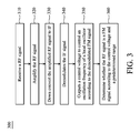
- FIG. 3 shows an FM signal receiving method 300 according to an embodiment of the invention.
- the FM receiver 200 receives an RF signal R via the antenna (step 310 ).
- the RF amplifier 210 amplifies the RF signal R (step 320 ).
- the mixer 220 down converts the amplified RF signal to an IF according to a local oscillation signal (step 330 ).
- the IF amplifier 230 amplifies the down converted signal to output an IF signal.
- the amplitude limiter 240 limits an amplitude of the IF signal to decrease noise.
- the FM demodulator 250 demodulates the limited IF signal to output a demodulated FM signal (step 340 ).
- the demodulated FM signal is transmitted to the AFC 260 , and the AFC 260 outputs a control voltage to control an oscillation frequency of the local oscillator 270 according to the demodulated FM signal (step 350 ).
- a loop formed by the mixer 220 , the IF amplifier 230 , the amplitude limiter 240 , the FM demodulator 250 , the AFC 260 and the local oscillator 270 may establish a feedback scheme.
- the feedback scheme may adjust the down-conversion error according to the demodulated FM signal such that the mixer 220 may accurately down convert the RF signal to a predetermined IF according to the local oscillation signal of the local oscillator 270 .
- the signal detector 280 determines whether the RF signal is the FM signal or not according to the control voltage and a predetermined voltage range (step 360 ).
- the predetermined voltage range is determined according to the actual communication status.
- FIG. 4 shows a block diagram illustrating the signal detector 280 according to an embodiment of the invention.
- the signal detector 280 comprises an average circuit 410 and a direct current (DC) voltage comparator 420 .
- the average circuit 410 is coupled to the AFC 260 , and the average circuit 410 receives the control voltage and outputs an average value of the control voltage.
- the average circuit 410 may be an integrator which integrates the control voltage during a predetermined time period and periodically outputs the integrated value.
- the average circuit 410 may also obtain a maximum value and a minimum value of the control voltage during a predetermined time period, and then the average circuit 410 may average the maximum and minimum values of the control voltage and periodically output the average value.
- the average circuit 410 may monitor the control voltage during a predetermined time period, thus avoiding error detection for the signal detector 280 , wherein the error detection is caused by unstable control voltage, sudden large noise or signal attenuation. Furthermore, one skilled in the art may design various types of circuits according to the desired function of the average circuit 410 .
- the voltage comparator 420 is coupled to the average circuit 410 . The voltage comparator 420 determines that the RF signal is the FM signal when the average value of the control voltage is within the predetermined voltage range, and the voltage comparator 420 determines that the RF signal is not the FM signal when the average value of the control voltage is not within the predetermined voltage range.
- FIG. 5 shows a schematic diagram illustrating the voltage comparator 420 according to an embodiment of the invention.
- the voltage comparator 420 comprises a first operational amplifier 510 , a second operational amplifier 520 and a AND logic gate 530 .
- the first operational amplifier 510 has an inverting input coupled to the average circuit 410 and a non-inverting input coupled to a first reference voltage V ref1 .
- the first operational amplifier 510 outputs a first comparing result according to the average value and the first reference voltage V ref1 .
- the first operational amplifier 510 When the first reference voltage V ref1 is larger than the average value, the first operational amplifier 510 outputs a high voltage to represent a logic “1”.
- the first operational amplifier 510 When the first reference voltage V ref1 is smaller than the average value, the first operational amplifier 510 outputs a low voltage to represent a logic “0”.
- the second operational amplifier 520 has a non-inverting input coupled to the average circuit 410 and an inverting input coupled to a second reference voltage V ref2 .
- the second operational amplifier 520 outputs a second comparing result according to the average value and the second reference voltage V ref2 .
- the second reference voltage V ref2 When the second reference voltage V ref2 is smaller than the average value, the second operational amplifier 520 outputs a high voltage to represent a logic “1”.
- the second operational amplifier 520 When the second reference voltage V ref2 is larger than the average value, the second operational amplifier 520 outputs a low voltage to represent a logic “0”.
- the first operational amplifier 510 may output a low voltage (i.e. logic “0”) when the average value is larger than the first reference voltage V ref1 or the second operational amplifier 520 may output a low voltage (i.e. logic “0”) when the average value is smaller than the second reference voltage V ref2 .
- the AND logic gate 530 is coupled to the first operational amplifier 510 and the second operational amplifier 520 , which outputs a determining signal to indicate whether the RF signal is the FM signal or not according to the first comparing result and the second comparing result.
- Both the first operational amplifier 510 and the second operational amplifier 520 may output a high voltage (i.e. logic “1”) simultaneously only when the first reference voltage>the average value>the second reference voltage. Therefore, the AND logic gate 530 outputs a logic “1” to indicate that the RF signal is the FM signal, and the AND logic gate 530 outputs a logic “0” to indicate that the RF signal is not the FM signal.
- a high voltage i.e. logic “1”
- the AND logic gate 530 outputs a logic “1” to indicate that the RF signal is the FM signal
- the AND logic gate 530 outputs a logic “0” to indicate that the RF signal is not the FM signal.
- the invention uses the AFC control voltage to determine whether the RF signal is the FM signal or not without use of the SNR, thus eliminating requirement for an SNR calculator. Furthermore, no additional circuits are required, as an AFC circuit is originally a required circuit for an FM receiver. Therefore, the invention decreases system complexity and cost for an FM receiver, and is able to determine whether the RF signal is the FM signal or not.
Abstract
A frequency modulation receiver is provided. The frequency modulation receiver includes an automatic frequency controller and a signal detector. The automatic frequency controller receives a demodulated frequency modulation signal demodulated from a radio frequency signal and outputs a control voltage to control an oscillation frequency of a local oscillator. The signal detector coupled to the automatic frequency controller receives the control voltage and determines whether the radio frequency signal is a frequency modulation signal according to the control voltage and a predetermined voltage range.
Description
This Application claims priority of Taiwan Patent Application No. 098114802, filed on May 5, 2009, the entirety of which is incorporated by reference herein.
1. Field of the Invention
The invention relates to a frequency modulation (FM) receiver and receiving method thereof, and more particularly to an FM receiver with a signal detector and receiving method thereof.
2. Description of the Related Art
Frequency modulation (FM) is one type of modulation technology in electronic communications, which uses carrier wave frequency variations of a transmitted signal provided by a transmitter to represent data to be sent. Usually, the data to be sent is shown as an electronic signal, such as an electronic signal with voice information, and the amplitude of the electronic signal is reflected on the carrier wave frequency variations of the transmitted signal through FM technology according to a ratio.
In general, an FM broadcast system (radio system) is one type of application for FM technology. At present, the FM broadcast system has a frequency range between 88-109 MHz which comprises 100 channels, wherein a bandwidth of each channel is 100 kHz. A user can use an FM receiver to select a desired channel. Usually, the FM receiver has a function for searching the FM signals. The FM receiver can automatically search the channels one by one to determine whether the radio frequency (RF) signal received in each channel is an FM signal or not, i.e. FM signal search, thus avoiding manual search for the user.
In general, an FM receiver determine whether an RF signal received in a channel is an FM signal or not according to an FM signal to noise ratio (SNR) of the channel. FIG. 1 shows a block diagram illustrating a conventional FM receiver 100. The FM receiver 100 receives an RF signal R. An RF amplifier 110 amplifies the RF signal R, and then a mixer 120 down converts the amplified RF signal R to an intermediate frequency (IF). Next, the RF signal R down converted to the IF may sequentially pass an IF amplifier 130, an amplitude limiter 140 and an FM demodulator 150 so as to obtain a demodulated FM signal. The demodulated FM signal is transmitted to an SNR calculator 180 to calculate a SNR. A signal detector 190 determines whether the RF signal is an FM signal or not according to the SNR and a predetermined threshold. However, because it is difficult to obtain the SNR, the method that uses the SNR determines whether the RF signal is the FM signal or not is deficient. Various methods are used to obtain the SNR, which separate the FM signal and the noise in the channel to calculate the FM signal intensity and the noise intensity so as to obtain the SNR. However, a more complex system is required, thus increasing cost for the FM receiver.
Therefore, an FM receiver and a receiving method thereof are desired to decrease system complexity and cost.
Frequency modulation receivers and receiving method thereof are provided. An exemplary embodiment of such a frequency modulation receiver for a frequency modulation system is provided. The frequency modulation receiver comprises an automatic frequency controller and a signal detector. The automatic frequency controller receives a demodulated frequency modulation signal demodulated from a radio frequency signal and outputs a control voltage to control an oscillation frequency of a local oscillator according to the demodulated frequency modulation signal. The signal detector coupled to the automatic frequency controller receives the control voltage and determines whether the radio frequency signal is a frequency modulation signal according to the control voltage and a predetermined voltage range.
Furthermore, an exemplary embodiment of a frequency modulation signal receiving method for a frequency modulation system is provided. A demodulated frequency modulation signal demodulated from a radio frequency signal is received, and a control voltage is output to control an oscillation frequency of a local oscillator according to the demodulated frequency modulation signal. It is determined whether the radio frequency signal is a frequency modulation signal according to the control voltage and a predetermined voltage range.
Moreover, another exemplary embodiment of a frequency modulation receiver for a frequency modulation system is provided. The frequency modulation receiver comprises an antenna, a radio frequency amplifier, a mixer, a frequency modulation demodulator, an automatic frequency controller, a signal detector and a local oscillator. The antenna receives a radio frequency signal. The radio frequency amplifier amplifies the radio frequency signal. The mixer receives the amplified radio frequency signal and a local oscillation signal, and down converts the amplified radio frequency signal to an intermediate frequency to output an intermediate frequency signal according to the local oscillation signal. The frequency modulation demodulator coupled to the mixer receives the intermediate frequency signal and demodulates the intermediate frequency signal to output a demodulated frequency modulation signal. The automatic frequency controller coupled to the frequency modulation demodulator receives the demodulated frequency modulation signal and outputs a control voltage according to the demodulated frequency modulation signal. The signal detector coupled to the automatic frequency controller receives the control voltage and determines whether the radio frequency signal is a frequency modulation signal according to the control voltage and a predetermined voltage range. The local oscillator outputs to the local oscillation signal according to the control voltage.
Furthermore, another exemplary embodiment of a frequency modulation signal receiving method for a frequency modulation system is provided. A radio frequency signal is received. The radio frequency signal is amplified. The amplified radio frequency signal is down converted to an intermediate frequency to output an intermediate frequency signal according to a local oscillation signal. The intermediate frequency signal is demodulated and a demodulated frequency modulation signal is output. A control voltage is output to control an oscillation frequency of a local oscillator according to the demodulated frequency modulation signal. It is determined whether the radio frequency signal is a frequency modulation signal according to the control voltage and a predetermined voltage range.
A detailed description is given in the following embodiments with reference to the accompanying drawings.
The invention can be more fully understood by reading the subsequent detailed description and examples with references made to the accompanying drawings, wherein:
The following description is of the best-contemplated mode of carrying out the invention. This description is made for the purpose of illustrating the general principles of the invention and should not be taken in a limiting sense. The scope of the invention is best determined by reference to the appended claims.
Next, the demodulated FM signal is transmitted to the AFC 260, and the AFC 260 outputs a control voltage to control an oscillation frequency of the local oscillator 270 according to the demodulated FM signal (step 350). A loop formed by the mixer 220, the IF amplifier 230, the amplitude limiter 240, the FM demodulator 250, the AFC 260 and the local oscillator 270 may establish a feedback scheme. The feedback scheme may adjust the down-conversion error according to the demodulated FM signal such that the mixer 220 may accurately down convert the RF signal to a predetermined IF according to the local oscillation signal of the local oscillator 270. The control voltage output by the AFC 260 has a relationship with that whether the RF signal is an FM signal or not. If the RF signal is not the FM signal, the feedback scheme would not able to down convert the RF signal to the predetermined IF. Thus, the control voltage output by the AFC 260 according to the demodulated FM signal (i.e. non-FM signal) would be different from the control voltage corresponding to the FM signal. Furthermore, if the RF signal is a weak FM signal, the feedback scheme would not be able to adjust the down-conversion error to an allowable range. So, the control voltage output by the AFC 260 according to the weak FM signal would also be different from the control voltage corresponding to the FM signal with satisfactory strength. Therefore, when the RF signal is a valid FM signal, the control voltage output by the AFC 260 is within a predetermined voltage range. On the contrary, it is determined that the RF signal is an invalid FM signal when the control voltage is not within the predetermined voltage range. As a result, the signal detector 280 determines whether the RF signal is the FM signal or not according to the control voltage and a predetermined voltage range (step 360). The predetermined voltage range is determined according to the actual communication status.
The invention uses the AFC control voltage to determine whether the RF signal is the FM signal or not without use of the SNR, thus eliminating requirement for an SNR calculator. Furthermore, no additional circuits are required, as an AFC circuit is originally a required circuit for an FM receiver. Therefore, the invention decreases system complexity and cost for an FM receiver, and is able to determine whether the RF signal is the FM signal or not.
While the invention has been described by way of example and in terms of preferred embodiment, it is to be understood that the invention is not limited thereto. Those who are skilled in this technology can still make various alterations and modifications without departing from the scope and spirit of this invention. Therefore, the scope of the present invention shall be defined and protected by the following claims and their equivalents.
Claims (8)
1. A frequency modulation receiver, comprising:
an automatic frequency controller, receiving a demodulated frequency modulation signal demodulated from a radio frequency signal and outputting a control voltage to control an oscillation frequency of a local oscillator according to the demodulated frequency modulation signal; and
a signal detector coupled to the automatic frequency controller, receiving the control voltage and determining whether the radio frequency signal is a frequency modulation signal according to the control voltage and a predetermined voltage range, wherein the signal detector further comprises:
an average circuit coupled to the automatic frequency controller, receiving the control voltage and outputting an average value of the control voltage; and
a voltage comparator coupled to the average circuit, wherein the voltage comparator determines that the radio frequency signal is the frequency modulation signal when the average value is within the predetermined voltage range, and the voltage comparator determines that the radio frequency signal is not the frequency modulation signal when the average value is not within the predetermined voltage range, wherein the voltage comparator further comprises:
a first operational amplifier coupled to the average circuit, outputting a first comparing result according to the average value and a first reference voltage;
a second operational amplifier coupled to the average circuit, outputting a second comparing result according to the average value and a second reference voltage; and
a AND logic gate coupled to the first operational amplifier and the second operational amplifier, outputting a determining signal to indicate whether the radio frequency signal is the frequency modulation signal according to the first comparing result and the second comparing result.
2. The frequency modulation receiver as claimed in claim 1 , wherein the average value is obtained according to an average of a maximum value and a minimum value of the control voltage during a first time period.
3. A frequency modulation signal receiving method, comprising:
receiving a demodulated frequency modulation signal demodulated from a radio frequency signal, and outputting a control voltage to control an oscillation frequency of a local oscillator according to the demodulated frequency modulation signal; and
determining whether the radio frequency signal is a frequency modulation signal according to the control voltage and a predetermined voltage range,
wherein the step of determining whether the radio frequency signal is the frequency modulation signal further comprises:
determining whether the radio frequency signal is the frequency modulation signal according to an average value of the control voltage;
determining that the radio frequency signal is the frequency modulation signal by a voltage comparator when the average value is within the predetermined voltage range; and
determining that the radio frequency signal is not the frequency modulation signal by the voltage comparator when the average value is not within the predetermined voltage range,
wherein the voltage comparator comprises:
a first operational amplifier, outputting a first comparing result according to the average value and a first reference voltage;
a second operational amplifier, outputting a second comparing result according to the average value and a second reference voltage; and
a AND logic gate coupled to the first operational amplifier and the second operational amplifier, outputting a determining signal to indicate whether the radio frequency signal is the frequency modulation signal according to the first comparing result and the second comparing result.
4. The frequency modulation signal receiving method as claimed in claim 3 , wherein the average value is obtained according to an average of a maximum value and a minimum value of the control voltage during a first time period.
5. A frequency modulation receiver, comprising:
an antenna, receiving a radio frequency signal;
a radio frequency amplifier, amplifying the radio frequency signal;
a mixer, receiving the amplified radio frequency signal and a local oscillation signal, and down converting the amplified radio frequency signal to an intermediate frequency to output an intermediate frequency signal according to the local oscillation signal;
a frequency modulation demodulator coupled to the mixer, receiving the intermediate frequency signal and demodulating the intermediate frequency signal to output a demodulated frequency modulation signal;
an automatic frequency controller coupled to the frequency modulation demodulator, receiving the demodulated frequency modulation signal and outputting a control voltage according to the demodulated frequency modulation signal;
a signal detector coupled to the automatic frequency controller, receiving the control voltage and determining whether the radio frequency signal is a frequency modulation signal according to the control voltage and a predetermined voltage range; and
a local oscillator, outputting the local oscillation signal according to the control voltage,
wherein the signal detector further comprises:
an average circuit coupled to the automatic frequency controller, receiving the control voltage and outputting an average value of the control voltage; and
a voltage comparator coupled to the average circuit, wherein the voltage comparator determines that the radio frequency signal is the frequency modulation signal when the average value is within the predetermined voltage range, and the voltage comparator determines that the radio frequency signal is not the frequency modulation signal when the average value is not within the predetermined voltage range, wherein the voltage comparator further comprises:
a first operational amplifier coupled to the average circuit, outputting a first comparing result according to the average value and a first reference voltage;
a second operational amplifier coupled to the average circuit, outputting a second comparing result according to the average value and a second reference voltage; and
a AND logic gate coupled to the first operational amplifier and the second operational amplifier, outputting a determining signal to indicate whether the radio frequency signal is the frequency modulation signal according to the first comparing result and the second comparing result.
6. The frequency modulation receiver as claimed in claim 5 , wherein the average value is obtained according to an average of a maximum value and a minimum value of the control voltage during a first time period.
7. A frequency modulation signal receiving method, comparing:
receiving a radio frequency signal;
amplifying the radio frequency signal; down converting the amplified radio frequency signal to an intermediate frequency to output an intermediate frequency signal according to a local oscillation signal;
demodulating the intermediate frequency signal and outputting a demodulated frequency modulation signal;
outputting a control voltage to control an oscillation frequency of a local oscillator according to the demodulated frequency modulation signal; and
determining whether the radio frequency signal is a frequency modulation signal according to the control voltage and a predetermined voltage range,
wherein the step of determining whether the radio frequency signal is the frequency modulation signal further comprises:
determining whether the radio frequency signal is the frequency modulation signal according to an average value of the control voltage;
determining that the radio frequency signal is the frequency modulation signal by a voltage comparator when the average value is within the predetermined voltage range; and
determining that the radio frequency signal is not the frequency modulation signal by the voltage comparator when the average value is not within the predetermined voltage range,
wherein the voltage comparator comprises:
a first operational amplifier, outputting a first comparing result according to the average value and a first reference voltage;
a second operational amplifier, outputting a second comparing result according to the average value and a second reference voltage; and
a AND logic gate coupled to the first operational amplifier and the second operational amplifier, outputting a determining signal to indicate whether the radio frequency signal is the frequency modulation signal according to the first comparing result and the second comparing result.
8. The frequency modulation signal receiving method as claimed in claim 7 , wherein the average value is obtained according to an average of a maximum value and a minimum value of the control voltage during a first time period.
Applications Claiming Priority (3)
| Application Number | Priority Date | Filing Date | Title |
|---|---|---|---|
| TW98114802A | 2009-05-05 | ||
| TW98114802 | 2009-05-05 | ||
| TW098114802A TWI410057B (en) | 2009-05-05 | 2009-05-05 | Frequency modulation receiver and receive method thereof |
Publications (2)
| Publication Number | Publication Date |
|---|---|
| US20100285764A1 US20100285764A1 (en) | 2010-11-11 |
| US8509717B2 true US8509717B2 (en) | 2013-08-13 |
Family
ID=43062615
Family Applications (1)
| Application Number | Title | Priority Date | Filing Date |
|---|---|---|---|
| US12/619,960 Active 2032-04-01 US8509717B2 (en) | 2009-05-05 | 2009-11-17 | Frequency modulation receiver and receiving method thereof |
Country Status (2)
| Country | Link |
|---|---|
| US (1) | US8509717B2 (en) |
| TW (1) | TWI410057B (en) |
Cited By (1)
| Publication number | Priority date | Publication date | Assignee | Title |
|---|---|---|---|---|
| US11362870B2 (en) * | 2020-07-03 | 2022-06-14 | Richwave Technology Corp. | Frequency modulation demodulation device and control method of frequency modulation demodulation device |
Citations (13)
| Publication number | Priority date | Publication date | Assignee | Title |
|---|---|---|---|---|
| US2840640A (en) * | 1955-12-14 | 1958-06-24 | Collins Radio Co | Mechanical filter frequency discriminator |
| US2896074A (en) * | 1953-07-31 | 1959-07-21 | Gen Precision Lab Inc | Frequency tracker with fixedly-spaced local oscillations equally offset from unknown frequency |
| US2976411A (en) * | 1958-06-16 | 1961-03-21 | Leonard R Kahn | Automatic frequency control system suitable for single-sideband receivers, frequency modulation transmitters and the like |
| US2977409A (en) * | 1958-04-09 | 1961-03-28 | Westinghouse Electric Corp | Television apparatus for weak signal tuning |
| US3947774A (en) * | 1974-11-25 | 1976-03-30 | General Motors Corporation | Signal seeking stopping circuit receiver |
| US4092602A (en) * | 1975-06-02 | 1978-05-30 | Onkyo Kabushiki Kaisha | Automatic frequency control for FM-receiver |
| US4387469A (en) * | 1980-06-03 | 1983-06-07 | Clarion Co., Ltd. | Tuner control system |
| US4450586A (en) * | 1980-05-26 | 1984-05-22 | Nippon Atsudenki Kabushiki Kaisha | Automatic tuning device for FM receiver |
| US4814887A (en) * | 1988-05-23 | 1989-03-21 | General Instrument Corporation | Automatic frequency control |
| US4955074A (en) * | 1988-05-30 | 1990-09-04 | Matsushita Electric Industrial Co., Ltd. | AFC apparatus with selection between average value mode and keyed mode |
| US5963600A (en) * | 1997-03-04 | 1999-10-05 | Northrop Grumman Corporation | Micro-controller based frequency calibration |
| US6223061B1 (en) * | 1997-07-25 | 2001-04-24 | Cleveland Medical Devices Inc. | Apparatus for low power radio communications |
| US20090061801A1 (en) * | 2007-09-04 | 2009-03-05 | Sanyo Electric Co., Ltd. | FM Tuner |
Family Cites Families (1)
| Publication number | Priority date | Publication date | Assignee | Title |
|---|---|---|---|---|
| CA1259378A (en) * | 1985-09-19 | 1989-09-12 | Noriaki Omoto | A.f.c. system for broad-band fm receiver |
-
2009
- 2009-05-05 TW TW098114802A patent/TWI410057B/en active
- 2009-11-17 US US12/619,960 patent/US8509717B2/en active Active
Patent Citations (13)
| Publication number | Priority date | Publication date | Assignee | Title |
|---|---|---|---|---|
| US2896074A (en) * | 1953-07-31 | 1959-07-21 | Gen Precision Lab Inc | Frequency tracker with fixedly-spaced local oscillations equally offset from unknown frequency |
| US2840640A (en) * | 1955-12-14 | 1958-06-24 | Collins Radio Co | Mechanical filter frequency discriminator |
| US2977409A (en) * | 1958-04-09 | 1961-03-28 | Westinghouse Electric Corp | Television apparatus for weak signal tuning |
| US2976411A (en) * | 1958-06-16 | 1961-03-21 | Leonard R Kahn | Automatic frequency control system suitable for single-sideband receivers, frequency modulation transmitters and the like |
| US3947774A (en) * | 1974-11-25 | 1976-03-30 | General Motors Corporation | Signal seeking stopping circuit receiver |
| US4092602A (en) * | 1975-06-02 | 1978-05-30 | Onkyo Kabushiki Kaisha | Automatic frequency control for FM-receiver |
| US4450586A (en) * | 1980-05-26 | 1984-05-22 | Nippon Atsudenki Kabushiki Kaisha | Automatic tuning device for FM receiver |
| US4387469A (en) * | 1980-06-03 | 1983-06-07 | Clarion Co., Ltd. | Tuner control system |
| US4814887A (en) * | 1988-05-23 | 1989-03-21 | General Instrument Corporation | Automatic frequency control |
| US4955074A (en) * | 1988-05-30 | 1990-09-04 | Matsushita Electric Industrial Co., Ltd. | AFC apparatus with selection between average value mode and keyed mode |
| US5963600A (en) * | 1997-03-04 | 1999-10-05 | Northrop Grumman Corporation | Micro-controller based frequency calibration |
| US6223061B1 (en) * | 1997-07-25 | 2001-04-24 | Cleveland Medical Devices Inc. | Apparatus for low power radio communications |
| US20090061801A1 (en) * | 2007-09-04 | 2009-03-05 | Sanyo Electric Co., Ltd. | FM Tuner |
Cited By (1)
| Publication number | Priority date | Publication date | Assignee | Title |
|---|---|---|---|---|
| US11362870B2 (en) * | 2020-07-03 | 2022-06-14 | Richwave Technology Corp. | Frequency modulation demodulation device and control method of frequency modulation demodulation device |
Also Published As
| Publication number | Publication date |
|---|---|
| TW201041324A (en) | 2010-11-16 |
| TWI410057B (en) | 2013-09-21 |
| US20100285764A1 (en) | 2010-11-11 |
Similar Documents
| Publication | Publication Date | Title |
|---|---|---|
| US7890075B2 (en) | Mechanism for controlling amplifier gain in a radio receiver | |
| US7580690B2 (en) | High-frequency receiver having a gain switch controller | |
| US8442154B2 (en) | Channel sensitive power control | |
| US7072632B2 (en) | Fast signal detection process | |
| US8121572B2 (en) | Signal strength detecting device and related method | |
| US20080248752A1 (en) | Radio transmission system, transmitter and radio transmission method | |
| US8619196B2 (en) | Broadcast receiver utilizing either signal amplification or signal attenuation | |
| US8055225B2 (en) | FM receiver | |
| US20100014618A1 (en) | Receiving device | |
| US8041322B2 (en) | RF receiver device | |
| US7373125B2 (en) | Off-channel signal detector with programmable hysteresis | |
| US8509717B2 (en) | Frequency modulation receiver and receiving method thereof | |
| JP4159964B2 (en) | Audio broadcast receiving apparatus and automatic channel selection method | |
| KR100651493B1 (en) | Apparatus and method for controllin gain in receiver | |
| JP2003318756A (en) | Digital radio receiver | |
| US20060030272A1 (en) | Transceiver and receiver | |
| CN108880587B (en) | Receiver for receiving radio frequency signal, processing method and wireless communication equipment | |
| CN101989885A (en) | Frequency modulation receiver and receiving method thereof | |
| EP1612955A1 (en) | Transceiver and receiver | |
| GB2393052A (en) | Control of the bias in an amplifier or mixer of a receiver for improved dynamic range, noise performance and efficiency | |
| JP2009273093A (en) | Fm receiver | |
| EP2670051A2 (en) | Signal processing apparatus, system and method for automatic gain control using the same | |
| JP4742859B2 (en) | Radio, control method and program | |
| US20040053596A1 (en) | Radio receiver | |
| US20080211970A1 (en) | Television reception circuit and television reception apparatus |
Legal Events
| Date | Code | Title | Description |
|---|---|---|---|
| AS | Assignment |
Owner name: RICHWAVE TECHNOLOGY CORP., TAIWAN Free format text: ASSIGNMENT OF ASSIGNORS INTEREST;ASSIGNOR:SHIU, HUEI-CHIANG;REEL/FRAME:023528/0792 Effective date: 20091105 |
|
| STCF | Information on status: patent grant |
Free format text: PATENTED CASE |
|
| FPAY | Fee payment |
Year of fee payment: 4 |
|
| MAFP | Maintenance fee payment |
Free format text: PAYMENT OF MAINTENANCE FEE, 8TH YR, SMALL ENTITY (ORIGINAL EVENT CODE: M2552); ENTITY STATUS OF PATENT OWNER: SMALL ENTITY Year of fee payment: 8 |