US8503092B2 - Zoom lens, optical apparatus and method of manufacturing zoom lens - Google Patents
Zoom lens, optical apparatus and method of manufacturing zoom lens Download PDFInfo
- Publication number
- US8503092B2 US8503092B2 US13/215,381 US201113215381A US8503092B2 US 8503092 B2 US8503092 B2 US 8503092B2 US 201113215381 A US201113215381 A US 201113215381A US 8503092 B2 US8503092 B2 US 8503092B2
- Authority
- US
- United States
- Prior art keywords
- lens
- lens group
- end state
- zoom
- zoom lens
- Prior art date
- Legal status (The legal status is an assumption and is not a legal conclusion. Google has not performed a legal analysis and makes no representation as to the accuracy of the status listed.)
- Active
Links
Images


Classifications
-
- G—PHYSICS
- G02—OPTICS
- G02B—OPTICAL ELEMENTS, SYSTEMS OR APPARATUS
- G02B15/00—Optical objectives with means for varying the magnification
- G02B15/14—Optical objectives with means for varying the magnification by axial movement of one or more lenses or groups of lenses relative to the image plane for continuously varying the equivalent focal length of the objective
- G02B15/16—Optical objectives with means for varying the magnification by axial movement of one or more lenses or groups of lenses relative to the image plane for continuously varying the equivalent focal length of the objective with interdependent non-linearly related movements between one lens or lens group, and another lens or lens group
- G02B15/177—Optical objectives with means for varying the magnification by axial movement of one or more lenses or groups of lenses relative to the image plane for continuously varying the equivalent focal length of the objective with interdependent non-linearly related movements between one lens or lens group, and another lens or lens group having a negative front lens or group of lenses
-
- G—PHYSICS
- G02—OPTICS
- G02B—OPTICAL ELEMENTS, SYSTEMS OR APPARATUS
- G02B15/00—Optical objectives with means for varying the magnification
- G02B15/14—Optical objectives with means for varying the magnification by axial movement of one or more lenses or groups of lenses relative to the image plane for continuously varying the equivalent focal length of the objective
- G02B15/143—Optical objectives with means for varying the magnification by axial movement of one or more lenses or groups of lenses relative to the image plane for continuously varying the equivalent focal length of the objective having three groups only
- G02B15/1435—Optical objectives with means for varying the magnification by axial movement of one or more lenses or groups of lenses relative to the image plane for continuously varying the equivalent focal length of the objective having three groups only the first group being negative
- G02B15/143507—Optical objectives with means for varying the magnification by axial movement of one or more lenses or groups of lenses relative to the image plane for continuously varying the equivalent focal length of the objective having three groups only the first group being negative arranged -++
Definitions
- the present invention relates to a zoom lens, an optical apparatus, and a method of manufacturing the zoom lens.
- zoom lenses used for image capturing lenses.
- a zoom lens comprised of three lens groups, that is, in order from an object, a negative lens group, a positive lens group, and a positive lens group, has been disclosed (e.g. see Japanese Laid-open Patent Publication No. 2009-282466(A)).
- a first aspect of the present invention is a zoom lens comprising, in order from an object, a first lens group having negative refractive power, a second lens group having positive refractive power, and a third lens group having positive refractive power, and the second lens group further comprises three or more cemented lenses.
- the third lens group is constituted only by a single lens.
- the first lens group and the second lens group move so that the distance between the first lens group and the second lens group decreases, and the distance between the second lens group and the third lens group increases, and the third lens group is fixed during zooming.
- the first lens group is constituted at least by three lenses, that is, in order from the object, a first negative lens, a second negative lens and a positive lens.
- At least one of the first negative lens and the second negative lens constituting the first lens group has an aspherical surface.
- the second lens group has a positive lens, and at least one of the positive lenses has an aspherical surface.
- an aperture stop for determining brightness is disposed in the second lens group.
- a diaphragm for cutting unnecessary external light is disposed between the first lens group and the second lens group, and moves upon zooming from the wide-angle end state to the telephoto end state.
- image blur is corrected by shifting the cemented lens disposed closest to the object in the second lens group in a direction approximately perpendicular to the optical axis.
- f 2 F denotes a focal length of the cemented lens disposed closest to the object
- f 2 M denotes a focal length of the cemented lens disposed second closest to the object, in the second lens group.
- f 2 F denotes a focal length of the cemented lens disposed closest to the object
- f 2 MR denotes a combined focal length of the cemented lenses disposed second and third closest to the object, in the second lens group.
- An optical apparatus includes the zoom lens.
- a method of manufacturing a zoom lens according to the present invention is constituted to manufacture the above mentioned zoom lens.
- the first lens group and the second lens group move so that the distance between the first lens group and the second lens group decreases, and the distance between the second lens group and the third lens group increases, and the third lens group is fixed during zooming.
- the first lens group is constituted by at least three lenses, that is, in order from the object, a first negative lens, a second negative lens and a positive lens.
- image blur is corrected by shifting the cemented lens disposed closest to the object in the second lens group in a direction approximately perpendicular to the optical axis.
- f 2 F denotes a focal length of the cemented lens disposed closest to the object
- f 2 M denotes a focal length of the cemented lens disposed second closest to the object, in the second lens group.
- f 2 F/f 2 MR denotes a focal length of the cemented lens disposed closest to the object
- f 2 MR denotes a combined focal length of the cemented lenses disposed second and third closest to the object, in the second lens group.
- a compact and ultra-high image quality zoom lens and optical apparatus and a method of manufacturing the zoom lens, can be provided.
- FIG. 1 is a diagram depicting a configuration and a zoom locus from a wide-angle end state (W) to a telephoto end state (T) of a zoom lens according to Example 1;
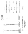
- FIG. 2 are graphs showing various aberrations of the zoom lens according to Example 1, where FIG. 2A are graphs showing various aberrations of the zoom lens upon focusing on infinity in the wide-angle end state, FIG. 2B are graphs showing various aberrations of the zoom lens upon focusing on infinity in the intermediate focal length state, and FIG. 2C are graphs showing various aberrations of the zoom lens upon focusing on infinity in the telephoto end state;
- FIG. 3 is a diagram depicting a configuration and a zoom locus from a wide-angle end state (W) to a telephoto end state (T) of a zoom lens according to Example 2;
- FIG. 4 are graphs showing various aberrations of the zoom lens according to Example 2, where FIG. 4A are graphs showing various Aberrations of the zoom lens upon focusing on infinity in the wide-angle end state, FIG. 4B are graphs showing various aberrations of the zoom lens upon focusing on infinity in the intermediate focal length state, and FIG. 4C are graphs showing various aberrations of the zoom lens upon focusing on infinity in the telephoto end state;
- FIG. 5 is a diagram depicting a configuration and a zoom locus from a wide-angle end state (W) to a telephoto end state (T) of a zoom lens according to Example 3;
- FIG. 6 are graphs showing various aberrations of the zoom lens according to Example 3, where FIG. 6A are graphs showing various aberrations of the zoom lens upon focusing on infinity in the wide-angle end state, FIG. 6B are graphs showing various aberrations of the zoom lens upon focusing on infinity in the intermediate focal length state, and FIG. 6C are graphs showing various aberrations of the zoom lens upon focusing on infinity in the telephoto end state;
- FIG. 7 is a diagram depicting a configuration and a zoom locus from a wide-angle end state (W) to a telephoto end state (T) of a zoom lens according to Example 4;
- FIG. 8 are graphs showing various aberrations of the zoom lens according to Example 4, where FIG. 8A are graphs showing various Aberrations of the zoom lens upon focusing on infinity in the wide-angle end state, FIG. 8B are graphs showing various aberrations of the zoom lens upon focusing on infinity in the intermediate focal length state, and FIG. 8C are graphs showing various aberrations of the zoom lens upon focusing on infinity in the telephoto end state;
- FIG. 9 is a diagram depicting a configuration and a zoom locus from a wide-angle end state (W) to a telephoto end state (T) of a zoom lens according to Example 5;
- FIG. 10 are graphs showing various aberrations of the zoom lens according to Example 5, where FIG. 10A are graphs showing various aberrations of the zoom lens upon focusing on infinity in the wide-angle end state, FIG. 10B are graphs showing various aberrations of the zoom lens upon focusing on infinity in the intermediate focal length state, and FIG. 10C are graphs showing various aberrations of the zoom lens upon focusing on infinity in the telephoto end state;
- FIG. 11 are graphs showing various aberrations of the zoom lens according to Example 5 after image blur correction, where FIG. 11A are graphs showing various aberrations of the zoom lens upon focusing on infinity in the wide-angle end state after image blur correction, FIG. 11B are graphs showing various aberrations of the zoom lens upon focusing on infinity in the intermediate focal length state after image blur correction, and FIG. 11C are graphs showing various aberrations of the zoom lens upon focusing on infinity in the telephoto end state;
- FIG. 12 is a diagram depicting a configuration and a zoom locus from a wide-angle end state (W) to a telephoto end state (T) of a zoom lens according to Example 6;
- FIG. 13 are graphs showing various aberrations of the zoom lens according to Example 6, where FIG. 13A are graphs showing various aberrations of the zoom lens upon focusing on infinity in the wide-angle end state, FIG. 13B are graphs showing various aberrations of the zoom lens upon focusing on infinity in the intermediate focal length state, and FIG. 13C are graphs showing various aberrations of the zoom lens upon focusing on infinity in the telephoto end state;
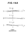
- FIG. 14 are graphs showing various aberrations of the zoom lens according to Example 6 after image blur correction, where FIG. 14A are graphs showing various aberrations of the zoom lens upon focusing on infinity in the wide-angle end state after image blur correction, FIG. 14B are graphs showing various aberrations of the zoom lens upon focusing on infinity in the intermediate focal length state after image blur correction, and FIG. 14C are graphs showing various aberrations of the zoom lens upon focusing on infinity in the telephoto end state;
- FIG. 15 is a diagram depicting a configuration and a zoom locus from a wide-angle end state (W) to a telephoto end state (T) of a zoom lens according to Example 7;
- FIG. 16 are graphs showing various aberrations of the zoom lens according to Example 7, where FIG. 16A are graphs showing various aberrations of the zoom lens upon focusing on infinity in the wide-angle end state, FIG. 16B are graphs showing various aberrations of the zoom lens upon focusing on infinity in the intermediate focal length state, and FIG. 16C are graphs showing various aberrations of the zoom lens upon focusing on infinity in the telephoto end state;
- FIG. 17 are graphs showing various aberrations of the zoom lens according to Example 7 after image blur correction, where FIG. 17A are graphs showing various aberrations of the zoom lens upon focusing on infinity in the wide-angle end state after image blur correction, FIG. 17B are graphs showing various aberrations of the zoom lens upon focusing on infinity in the intermediate focal length state after image blur correction, and FIG. 17C are graphs showing various aberrations of the zoom lens upon focusing on infinity in the telephoto end state;
- FIG. 18 is a diagram depicting a configuration and a zoom locus from a wide-angle end state (W) to a telephoto end state (T) of a zoom lens according to Example 8;
- FIG. 19 are graphs showing various aberrations of the zoom lens according to Example 8, where FIG. 19A are graphs showing various aberrations of the zoom lens upon focusing on infinity in the wide-angle end state, FIG. 19B are graphs showing various aberrations of the zoom lens upon focusing on infinity in the intermediate focal length state, and FIG. 19C are graphs showing various aberrations of the zoom lens upon focusing on infinity in the telephoto end state;
- FIG. 20 are graphs showing various aberrations of the zoom lens according to Example 8 after image blur correction
- FIG. 20A are graphs showing various aberrations of the zoom lens upon focusing on infinity in the wide-angle end state after image blur correction
- FIG. 20B are graphs showing various aberrations of the zoom lens upon focusing on infinity in the intermediate focal length state after image blur correction
- FIG. 20C are graphs showing various aberrations of the zoom lens upon focusing on infinity in the telephoto end state;
- FIG. 21 is an external view of a digital camera according to the present embodiment, where FIG. 21A is a front view of the digital still camera, and FIG. 21B is a rear view of the digital still camera;
- FIG. 22 is a flow chart depicting a first method of manufacturing the zoom lens according to the present embodiment.
- FIG. 23 is a flow chart depicting a second method of manufacturing the zoom lens according to the present embodiment.
- a zoom lens according to a first embodiment is a zoom lens comprising, in order from an object, a first lens group G 1 having negative refractive power, a second lens group G 2 having positive refractive power, and a third lens group G 3 having positive refractive power, wherein the second lens group G 2 is constituted only by three or more cemented lenses.
- the apparatus can be downsized, preventing the lens diameter from becoming too larger in the wide-angle end state, and fluctuation of astigmatism due to zooming can be corrected well. Since three or more cemented lenses are disposed in the second lens group G 2 , fluctuation of lateral chromatic aberration during zooming can be corrected well. Furthermore even if ultra-high image quality is demanded for the electronic still cameras, and sensors become larger and resolutions thereof increase in future, a zoom lens having high optical performance that can support this possibility can be obtained.
- Dt 23 denotes a distance between the second lens group G 2 and the third lens group G 3 in the telephoto end state
- Dt 3 i denotes a distance between the third lens group G 3 and the image plane (converted to air) in the telephoto end state
- Dt 23 denotes a distance between the second lens group G 2 and the third lens group G 3 in the telephoto end state
- Dt 3 i denotes a distance between the third lens group G 3 and the image plane (converted to air) in the telephoto end state” means a distance from the lens surface closest to the image constituting the third lens group G 3 to the image plane in the telephoto end state. 3.00 ⁇ Dt 23/ Dt 3 i ⁇ 30.00 (1)
- the conditional expression (1) specifies an appropriate ratio of the air distance of the third lens group G 3 to the object side, and the air distance thereof to the image side. If the upper limit value of the conditional expression (1) is exceeded, it becomes difficult to correct astigmatism well, which is not desirable. If the lower limit value of the conditional expression (1) is not reached, it becomes difficult to correct coma aberration well, which is not desirable.
- the upper limit value of the conditional expression (1) is 20.0. To further ensure the effect of the present embodiment, it is preferable that the upper limit value of the conditional expression (1) is 10.0.
- the lower limit value of the conditional expression (1) is 3.50. To further ensure the effect of the present embodiment, it is preferable that the lower limit value of the conditional expression (1) is 4.00. To even further ensure the effect of the present embodiment, it is preferable that the lower limit value of the conditional expression (1) is 4.50.
- f 2 denotes a focal length of the second lens group G 2
- f 3 denotes a focal length of the third lens group G 3 . 0.10 ⁇ f 2/ f 3 ⁇ 0.50 (2)
- the conditional expression (2) specifies an appropriate ratio of the focal length of the second lens group G 2 and the focal length of the third lens group G 3 . If the upper limit value of the conditional expression (2) is exceeded, the total length of the optical system becomes long, which is not desirable. It also becomes difficult to correct coma aberration well, which is not desirable. If the lower limit value of the conditional expression (2) is not reached, it becomes difficult to correct spherical aberration well, which is not desirable.
- the upper limit value of the conditional expression (2) is 0.45. To further ensure the effect of the present embodiment, it is preferable that the upper limit value of the conditional expression (2) is 0.40.
- the lower limit value of the conditional expression (2) is 0.15. To further ensure the effect of the present embodiment, it is preferable that the lower limit value of the conditional expression (2) is 0.20.
- the third lens group G 3 is constituted only by a single lens.
- the third lens group G 3 is constituted only by a single lens like this, assembly adjustment becomes extremely easy, which is effective for decreasing cost. Furthermore, the space required for housing the lenses decreases, so the size of the apparatus when carrying can be decreased. Using the single lens also enables correcting longitudinal chromatic aberration well.
- the first lens group G 1 and the second lens group G 2 move upon zooming from the wide-angle end stat to the telephoto end state so that the distance between the first lens group G 1 and the second lens group G 2 decreases, and the distance between the second lens group G 2 and the third lens group G 3 increases, and the third lens group G 3 is fixed.
- each lens group position during zooming can be controlled by one cam drum, and the position of the image plane during zooming can be accurately controlled as a result.
- Fixing the third lens group G 3 during zooming can decrease deterioration of astigmatism due to positional shift of the third lens group G 3 .
- the first lens group G 1 is constituted by three lenses, which are, in order from the object, a first negative lens, a second negative lens and a positive lens.
- At least one of the first negative lens and the second negative lens constituting the first lens group G 1 has an aspherical surface.
- the second lens group G 2 has positive lenses, and at least one of the positive lenses constituting the second lens group G 2 has an aspherical surface.
- an aperture stop for determining brightness is disposed in the second lens group G 2 .
- a diaphragm for cutting unnecessary external light is disposed between the first lens group G 1 and the second lens group G 2 , and moves upon zooming from the wide-angle end state to the telephoto end state. Since unnecessary external light in the wide-angle end state can be effectively cut by this configuration, coma aberration in the wide-angle end state can be corrected well.
- FIG. 21 shows a digital still camera CAM (optical apparatus) having the zoom lens as an image capturing lens ZL. If a power button, which is not illustrated, is pressed on this digital still camera CAM, a shutter, which is not illustrated, of the image capturing lens ZL is released and lights from an object are collected by the image-capturing lens ZL and form an image on a picture element (e.g. CCD, CMOS), which is disposed on the image plane I (see FIG. 1 ). The object image formed on the picture element is displayed on a liquid crystal monitor M disposed behind the digital still camera CAM. The user determines the composition of the object image while viewing the liquid crystal monitor M, then presses a release button B 1 to capture the object image by the picture element, and stores it in memory, which is not illustrated.
- a power button which is not illustrated
- the camera CAM has an auxiliary light emitting unit D, which emits auxiliary light when the object is dark, a wide (W)—telephoto (T) button B 2 for zooming the image capturing lens ZL from the wide-angle end state (W) to the telephoto end state (T), and a function button B 3 , which is used for setting various conditions for the digital still camera CAM.
- first to third lens groups e.g. first to third lens groups G 1 to G 3 in FIG. 1
- each lens is disposed so that the first lens group has negative refractive power, the second lens group has positive refractive power and the third lens group has positive refractive power.
- step S 2 only three or more cemented lens are disposed.
- each lens When each lens is assembled in the lens barrel, each lens may be assembled in the lens barrel one at a time in order along the optical axis, or a part or all of the lenses may be integratedly held on a holding member, and then assembled in the lens barrel. After assembling each lens group in the lens barrel like this, it is checked whether the object image is formed in a state where each lens group is assembled in the lens barrel, that is, whether the center of each lens is aligned, and then various operations of the zoom lens are checked. Examples of the various operations are a zoom operation in which lens groups which perform zooming from the wide-angle end state to the telephoto end state (e.g.
- first lens group G 1 , diaphragms S 1 , S 2 , and second lens group G 2 in this embodiment move along the optical axis
- a focusing operation in which a lens group which performs focusing from an object at a long distance to an object at a short distance (e.g. third lens group G 3 in this embodiment) moves along the optical axis
- a hand motion blur correction operation in which at least a part of the lenses (e.g. at least a part of the second lens group G 2 in this embodiment) move so as to have components orthogonal to the optical axis.
- the sequence of checking the various operations is arbitrary. According to this manufacturing method, a compact and ultra-high image quality zoom lens can be obtained.
- Example 1 to Example 4 according to the first embodiment will be described with reference to the drawings.
- Table 1 to Table 4 are tables listing each data according to Example 1 to Example 4.
- the surface number is a sequence of the lens surface counted from the object side along the light traveling direction
- r is a radius of curvature of each lens surface
- d is a distance between surfaces, which is a distance from each optical plane to the next optical plane (or image plane)
- nd is a refractive index at d-line (wavelength: 587.6 nm)
- ⁇ d is an Abbe number at d-line.
- “ ⁇ ” in the radius of curvature indicates a plane or an aperture.
- the refractive index of air 1.000000 is omitted.
- f is a focal length
- FNo is an F number
- ⁇ is a half angle of view
- Y is an image height
- TL is a total lens length
- Bf is a distance from an image side surface of the optical member disposed closest to the image to a paraxial image plane
- Bf (converted to air) is a distance converted to air from the last lens surface to the paraxial image plane.
- Di (i is an integer) in each state of the wide-angle end state, intermediate focal length state and telephoto end state is a variable distance between the i-th surface and the (i+1)th surface.
- G is a group number
- First surface of group is a surface number of a surface closest to the object in each group
- Fluor length of group is a focal length of each group
- Total lens length is a distance from the lens surface closest to the object to the lens surface closest to the image in each group on the optical axis.
- mm is normally used for the unit of focal length f, radius of curvature r, surface distance d and other lengths unless otherwise specified, but the unit is not limited to “mm”, since the equivalent optical performance is obtained even if an optical system is proportionally expanded or proportionally reduced.
- another appropriate unit may be used without being limited to “mm”.
- FIG. 1 is a diagram depicting a configuration of a zoom lens ZL (ZL 1 ) according to Example 1, and a zoom lens from a wide-angle end state (W) to a telephoto end state (T) thereof.
- the zoom lens ZL 1 according to Example 1 has, in order from an object, a first lens group G 1 having negative refractive power, a second lens group G 2 having positive refractive power, and a third lens group G 3 having positive refractive power.
- the first lens group G 1 and the second lens group G 2 move respectively so that the distance between the first lens group G 1 and the second lens group G 2 decreases, the distance between the second lens group G 2 and the third lens group G 3 increases, and the third lens group G 3 is fixed.
- the first lens group G 1 is comprised of, in order from the object: a negative meniscus lens L 11 having a convex surface facing the object; a negative meniscus lens L 12 having a convex surface facing the object; and a positive meniscus lens L 13 having a convex surface facing the object.
- a diaphragm S 1 for cutting unnecessary external light is disposed between the first lens group G 1 and the second lens group G 2 , and moves toward the object upon zooming from the wide-angle end state to the telephoto end state.
- the second lens group G 2 is comprised of, in order from the object: a cemented lens of a negative meniscus lens L 21 having a convex surface facing the object and a biconvex positive lens L 22 ; a cemented lens of a biconvex positive lens L 23 and a biconcave negative lens L 24 ; and a cemented lens of a negative meniscus lens L 25 having a convex surface facing the object and a biconvex positive lens L 26 .
- An aperture stop S 2 for adjusting quantity of light is disposed between the biconvex positive lens L 22 and the biconvex positive lens L 23 constituting the second lens group G 2 , and moves, together with the second lens group G 2 , toward the object upon zooming from the wide-angle end state to the telephoto end state.
- the third lens group G 3 is constituted by a biconvex positive lens L 31 .
- a glass block G such as a low pass filter and an infrared cut-off filter, for cutting off spatial frequencies exceeding a critical resolution of a picture element (e.g. CCD, CMOS), disposed on the Image plane I, and a sensor cover glass CV of the picture element are disposed.
- a picture element e.g. CCD, CMOS
- Table 1 shows each data value of Example 1.
- the surface numbers 1 to 23 in Table 1 correspond to the surfaces 1 to 23 in FIG. 1 .
- the second surface, eighth surface and eighteenth surface are formed to be aspherical.
- the zoom lens ZL 1 according to this example satisfies all the conditional expressions (1) and (2).
- FIG. 2 are graphs showing various aberrations of the zoom lens ZL 1 according to Example 1 (graphs showing spherical aberration, astigmatism, distortion, coma aberration and lateral chromatic aberration), where FIG. 2A are graphs showing various aberrations of the zoom lens upon focusing on infinity in the wide-angle end state, FIG. 2B are graphs showing various aberrations of the zoom lens upon focusing on infinity in the intermediate focal length state, and FIG. 2C are graphs showing various aberrations of the zoom lens upon focusing on infinity in the telephoto end state.
- FNo denotes an F number
- Y denotes an image height.
- the solid line indicates spherical aberration
- the broken line indicates the sine condition.
- the solid line indicates the sagittal image surface
- the broken line indicates the meridional image surface.
- the solid line indicates the meridional coma. The description on the graphs showing aberrations is the same for the other examples, where this description is omitted.
- Example 1 As the respective graphs on aberrations show, various aberrations are corrected well in each focal length state from the wide-angle end state to the telephoto end state, and excellent image forming performance is exhibited.
- FIG. 3 is a diagram depicting a configuration of a zoom lens ZL (ZL 2 ) according to Example 2, and a zoom lens from a wide-angle end state (W) to a telephoto end state (T) thereof.
- the zoom lens ZL 2 according to Example 2 has, in order from an object, a first lens group G 1 having negative refractive power, a second lens group G 2 having positive refractive power, and a third lens group G 3 having positive refractive power.
- the first lens group G 1 and the second lens group G 2 move respectively so that the distance between the first lens group G 1 and the second lens group G 2 decreases, the distance between the second lens group G 2 and the third lens group G 3 increases, and the third lens group G 3 is fixed.
- the first lens group G 1 is comprised of, in order from the object: a negative meniscus lens L 11 having a convex surface facing the object; a negative meniscus lens L 12 having a convex surface facing the object; and a positive meniscus lens L 13 having a convex surface facing the object.
- a diaphragm S 1 for cutting unnecessary external light is disposed between the first lens group G 1 and the second lens group G 2 , and moves toward the object upon zooming from the wide-angle end state to the telephoto end state.
- the second lens group G 2 is comprised of, in order from the object: a cemented lens of a negative meniscus lens L 21 having a convex surface facing the object and a biconvex positive lens L 22 ; a cemented lens of a positive meniscus lens L 23 having a convex surface facing the object, and a negative meniscus lens L 24 having a convex surface facing the object; and a cemented lens of a negative meniscus lens L 25 having a convex surface facing the object and a biconvex positive lens L 26 .
- An aperture stop S 2 for adjusting quantity of light is disposed between the biconvex positive lens L 22 and the positive meniscus lens L 23 having a convex surface facing the object constituting the second lens group G 2 , and moves, together with the second lens group G 2 , toward the object upon zooming from the wide-angle end state to the telephoto end state.
- the third lens group G 3 is constituted by a biconvex positive lens L 31 .
- a glass block G such as a low pass filter and an infrared cut-off filter, for cutting off spatial frequencies exceeding a critical resolution of a picture element (e.g. CCD, CMOS), disposed on the image plane I, and a sensor cover glass CV of the picture element are disposed.
- a picture element e.g. CCD, CMOS
- Table 2 shows each data value of Example 2.
- the surface numbers 1 to 23 in Table 2 correspond to the surfaces 1 to 23 in FIG. 3 .
- the second surface, eighth surface and eighteenth surface are formed to be aspherical.
- the zoom lens ZL 2 according to this example satisfies all the conditional expressions (1) and (2).
- FIG. 4 are graphs showing various aberrations of the zoom lens ZL 2 according to Example 2 (graphs showing spherical aberration, astigmatism, distortion, coma aberration and lateral chromatic aberration), where FIG. 4A are graphs showing various aberrations of the zoom lens upon focusing on infinity in the wide-angle end state, FIG. 4B are graphs showing various aberrations of the zoom lens upon focusing on infinity in the intermediate focal length state, and FIG. 4C are graphs showing various aberrations of the zoom lens upon focusing on infinity in the telephoto end state.
- Example 2 as the respective graphs on aberrations show, various aberrations are corrected well in each focal length state from the wide-angle end state to the telephoto end state, and excellent image forming performance is exhibited.
- FIG. 5 is a diagram depicting a configuration of a zoom lens ZL (ZL 3 ) according to Example 3, and a zoom lens from a wide-angle end state (W) to a telephoto end state (T) thereof.
- the zoom lens ZL 3 according to Example 3 has, in order from an object, a first lens group G 1 having negative refractive power, a second lens group G 2 having positive refractive power, and a third lens group G 3 having positive refractive power.
- the first lens group G 1 and the second lens group G 2 move respectively so that the distance between the first lens group G 1 and the second lens group G 2 decreases, the distance between the second lens group G 2 and the third lens group G 3 increases, and the third lens group G 3 is fixed.
- the first lens group G 1 is comprised of, in order from the object: a negative meniscus lens L 11 having a convex surface facing the object; a negative meniscus lens L 12 having a convex surface facing the object; and a positive meniscus lens L 13 having a convex surface facing the object.
- a diaphragm S 1 for cutting unnecessary external light is disposed between the first lens group G 1 and the second lens group G 2 , and moves toward the object upon zooming from the wide-angle end state to the telephoto end state.
- the second lens group G 2 is comprised of, in order from the object: a cemented lens of a negative meniscus lens L 21 having a convex surface facing the object and a biconvex positive lens L 22 ; a cemented lens of a positive meniscus lens L 23 having a convex surface facing the object and a negative meniscus lens L 24 having a convex surface facing the object; and a cemented lens of a negative meniscus lens L 25 having a convex surface facing the object and a biconvex positive lens L 26 .
- An aperture stop S 2 for adjusting quantity of light is disposed between the biconvex positive lens L 22 and the positive meniscus lens L 23 having a convex surface facing the object constituting the second lens group G 2 , and moves, together with the second lens group G 2 , toward the object upon zooming from the wide-angle end state to the telephoto end state.
- the third lens group G 3 is constituted by a biconvex positive lens L 31 .
- a glass block G such as a low pass filter and an infrared cut-off filter, for cutting off spatial frequencies exceeding a critical resolution of a picture element (e.g. CCD, CMOS), disposed on the image plane I, and a sensor cover glass CV of the picture element are disposed.
- a picture element e.g. CCD, CMOS
- Table 3 shows each data value of Example 3.
- the surface numbers 1 to 23 in Table 3 correspond to the surfaces 1 to 23 in FIG. 5 .
- the second surface, eighth surface and eighteenth surface are formed to be aspherical.
- the zoom lens ZL 3 according to this example satisfies all the conditional expressions (1) and (2).
- FIG. 6 are graphs showing various aberrations of the zoom lens ZL 3 according to Example 3 (graphs showing spherical aberration, astigmatism, distortion, coma aberration and lateral chromatic aberration), where FIG. 6A are graphs showing various aberrations of the zoom lens upon focusing on infinity in the wide-angle end state, FIG. 6B are graphs showing various aberrations of the zoom lens upon focusing on infinity in the intermediate focal length state, and FIG. 6 C are graphs showing various aberrations of the zoom lens upon focusing on infinity in the telephoto end state.
- Example 3 as the respective graphs on aberrations show, various aberrations are corrected well in each focal length state from the wide-angle end state to the telephoto end state, and excellent image forming performance is exhibited.
- FIG. 7 is a diagram depicting a configuration of a zoom lens ZL (ZL 4 ) according to Example 4, and a zoom lens from a wide-angle end state (W) to a telephoto end state (T) thereof.
- the zoom lens ZL 4 according to Example 4 has, in order from an object, a first lens group G 1 having negative refractive power, a second lens group G 2 having positive refractive power, and a third lens group G 3 having positive refractive power.
- the first lens group G 1 and the second lens group G 2 move respectively so that the distance between the first lens group G 1 and the second lens group G 2 decreases, the distance between the second lens group G 2 and the third lens group G 3 increases, and the third lens group G 3 is fixed.
- the first lens group G 1 is comprised of, in order from the object: a negative meniscus lens L 11 having a convex surface facing the object; a negative meniscus lens L 12 having a convex surface facing the object; and a positive meniscus lens L 13 having a convex surface facing the object.
- a diaphragm S 1 for cutting unnecessary external light is disposed between the first lens group G 1 and the second lens group G 2 , and moves toward the object upon zooming from the wide-angle end state to the telephoto end state.
- the second lens group G 2 is comprised of, in order from the object: a cemented lens of a negative meniscus lens L 21 having a convex surface facing the object and a biconvex positive lens L 22 ; a cemented lens of a positive meniscus lens L 23 having a convex surface facing the object and a negative meniscus lens L 24 having a convex surface facing the object; and a cemented lens of a negative meniscus lens L 25 having a convex surface facing the object and a biconvex positive lens L 26 .
- An aperture stop S 2 for adjusting quantity of light is disposed between the biconvex positive lens L 22 and the positive meniscus lens L 23 having a convex surface facing the object constituting the second lens group G 2 , and moves, together with the second lens group G 2 , toward the object upon zooming from the wide-angle end state to the telephoto end state.
- the third lens group G 3 is constituted by a biconvex positive lens L 31 .
- a glass block G such as a low pass filter and an infrared cut-off filter, for cutting off spatial frequencies exceeding a critical resolution of a picture element (e.g. CCD, CMOS), disposed on the image plane I, and a sensor cover glass CV of the picture element are disposed.
- a picture element e.g. CCD, CMOS
- Table 4 shows each data value of Example 4.
- the surface numbers 1 to 23 in Table 4 correspond to the surfaces 1 to 23 in FIG. 7 .
- the second surface, eighth surface and eighteenth surface are formed to be aspherical.
- the zoom lens ZL 4 according to this example satisfies all the conditional expressions (1) and (2).
- FIG. 8 are graphs showing various aberrations of the zoom lens ZL 4 according to Example 4 (graphs showing spherical aberration, astigmatism, distortion, coma aberration and lateral chromatic Aberration), where FIG. 8A are graphs showing various aberrations of the zoom lens upon focusing on infinity in the wide-angle end state, FIG. 8B are graphs showing various aberrations of the zoom lens upon focusing on infinity in the intermediate focal length state, and FIG. 8C are graphs showing various aberrations of the zoom lens upon focusing on infinity in the telephoto end state.
- Example 4 as the respective graphs on aberrations show, various aberrations are corrected well in each focal length state from the wide-angle end state to the telephoto end state, and excellent image forming performance is exhibited.
- a zoom lens according to the second embodiment is a zoom lens comprising, in order from an object, a first lens group G 1 having negative refractive power, a second lens group G 2 having positive refractive power, and a third lens group G 3 having positive refractive power, wherein the second lens group G 2 is constituted only by three or more cemented lenses.
- the apparatus can be downsized, preventing the lens diameter from becoming too larger in the wide-angle end state, and fluctuation of astigmatism due to zooming can be corrected well. Since three or more cemented lenses are disposed in the second lens group G 2 , fluctuation of lateral chromatic aberration during zooming can be corrected well.
- image blur is corrected by shifting the cemented lens disposed closest to the object among the second lens group G 2 roughly vertically to the optical axis. Because of this configuration, the amount of moving of the image plane upon shifting the cemented lens is large, so the required amount of shifting the cemented lens upon correcting image blur can be decreased, and fluctuation of coma aberration and fluctuation of astigmatism upon shifting the cemented lens for correcting image blur can be decreased. Since the amount of shifting the cemented lens is small and the cemented lens is much lighter and smaller compared with the method of shifting the entire lens group, the drive mechanism for shifting this cemented lens can be smaller, and therefore the size of the entire apparatus can be decreased.
- f 2 F denotes a focal length of the cemented lens disposed closest to the object in the second lens group G 2
- f 2 M denotes a focal length of the cemented lens disposed second closest to the object in the second lens group G 2 .
- the conditional expression (3) specifies an appropriate ratio of the focal length of the cemented lens disposed closest to the object and the focal length of the cemented lens disposed to the image plane side thereof (that is, disposed second closest to the object) among three or more cemented lenses disposed in the second lens group G 2 . If the upper limit value of the conditional expression (3) is exceeded, the moving amount of the image plane upon shifting the cemented lens disposed closest to the object in the second lens group G 2 becomes small, and it becomes difficult to correct fluctuation of coma aberration and fluctuation of astigmatism upon shifting the cemented lens for correcting image blur, which is not desirable. If the lower limit value of the conditional expression (3) is not reached, it becomes difficult to correct spherical aberration, which is not desirable.
- the upper limit value of the conditional expression (3) is 0.40. To further ensure the effect of the present embodiment, it is preferable that the upper limit value of the conditional expression (3) is 0.30.
- f 2 F denotes a focal length of the cemented lens disposed closest to the object in the second lens group G 2
- f 2 MR denotes a combined focal length of the cemented lenses disposed second and third closest to the object in the second lens group G 2 . 0.01 ⁇ f 2 F/f 2 MR ⁇ 0.2 (4)
- the conditional expression (4) specifies an appropriate ratio of the focal length of the cemented lens closest to the object and the combined focal length of the cemented lenses disposed second and third closest to the object among the three or more cemented lenses constituting the second lens group G 2 . If the upper limit value of the conditional expression (4) is exceeded, the moving amount of the image plane upon shifting the cemented lens disposed closest to the object in the second lens group G 2 becomes small, and it becomes difficult to correct fluctuation of coma aberration and fluctuation of astigmatism upon shifting the cemented lens for correcting image blur, which is not desirable. If the lower limit value of the conditional expression (4) is not reached, it becomes difficult to correct spherical aberration, which is not desirable.
- the upper limit value of the conditional expression (4) is 0.1.
- the lower limit value of the conditional expression (4) is 0.02.
- Dt 23 denotes a distance between the second lens group G 2 and the third lens group G 3 in the telephoto end state
- Dt 3 i denotes a distance between the third lens group G 3 and the image plane (converted to air) in the telephoto end state
- Dt 23 denotes a distance between the second lens group G 2 and the third lens group G 3 in the telephoto end state
- Dt 3 i denotes a distance between the third lens group G 3 and the image plane (converted to air) in the telephoto end state” means a distance from the lens surface closest to the image constituting the third lens group G 3 to the image plane in the telephoto end state. 3.00 ⁇ Dt 23/ Dt 3 i ⁇ 30.00 (5)
- the conditional expression (5) specifies an appropriate ratio of the air distance of the third lens group G 3 to the object side, and the air distance thereof to the image side. If the upper limit value of the conditional expression (5) is exceeded, it becomes difficult to correct astigmatism well, which is not desirable. If the lower limit value of the conditional expression (5) is not reached, it becomes difficult to correct coma aberration well, which is not desirable.
- the upper limit value of the conditional expression (5) is 20.00. To further ensure the effect of the present embodiment, it is preferable that the upper limit value of the conditional expression (5) is 10.00.
- the lower limit value of the conditional expression (5) is 3.50. To further ensure the effect of the present embodiment, it is preferable that the lower limit value of the conditional expression (5) is 4.00. To even further ensure the effect of the present embodiment, it is preferable that the lower limit value of the conditional expression (5) is 4.50.
- f 2 denotes a focal length of the second lens group G 2
- f 3 denotes a focal length of the third lens group G 3 . 0.10 ⁇ f 2/ f 3 ⁇ 0.50 (6)
- the conditional expression (6) specifies an appropriate ratio of the focal length of the second lens group G 2 and the focal length of the third lens group G 3 . If the upper limit value of the conditional expression (6) is exceeded, the total length of the optical system becomes long, which is not desirable. It also becomes difficult to correct coma aberration well, which is not desirable. If the lower limit value of the conditional expression (6) is not reached, it becomes difficult to correct spherical aberration well, which is not desirable.
- the upper limit value of the conditional expression (6) is 0.45. To further ensure the effect of the present embodiment, it is preferable that the upper limit value of the conditional expression (6) is 0.40.
- the lower limit value of the conditional expression (6) is 0.15. To further ensure the effect of the present embodiment, it is preferable that the lower limit value of the conditional expression (6) is 0.20.
- the third lens group G 3 is constituted only by a single lens.
- the third lens group G 3 is constituted only by a single lens like this, assembly adjustment becomes extremely easy, which is effective for decreasing cost. Furthermore, the space required for housing the lenses decreases, so the size of the apparatus when carrying can be decreased. Using the single lens also enables correcting longitudinal chromatic aberration well.
- the first lens group G 1 and the second lens group G 2 move upon zooming from the wide-angle end stat to the telephoto end state so that the distance between the first lens group G 1 and the second lens group G 2 decreases, and the distance between the second lens group G 2 and the third lens group G 3 increases, and the third lens group G 3 is fixed.
- each lens group position during zooming can be controlled by one cam drum, and the position of the image plane during zooming can be accurately controlled as a result.
- Fixing the third lens group G 3 during zooming can decrease deterioration of astigmatism due to positional shift of the third lens group G 3 .
- the first lens group G 1 is constituted by three lenses, which are, in order from the object, a first negative lens, a second negative lens and a positive lens.
- At least one of the first negative lens and the second negative lens constituting the first lens group G 1 has an aspherical surface.
- the second lens group G 2 has positive lenses, and at least one of the positive lenses constituting the second lens group G 2 has an aspherical surface.
- an aperture stop for determining brightness is disposed between the first lens group G 1 and the cemented lens having positive refractive power constituting the second lens group G 2 .
- a diaphragm for cutting unnecessary external light is disposed between the first lens group G 1 and the second lens group G 2 , and moves upon zooming from the wide-angle end state to the telephoto end state. Since unnecessary external light in the wide-angle end state can be effectively cut by this configuration, coma aberration in the wide-angle end state can be corrected well.
- FIG. 21 shows a digital still camera CAM (optical apparatus) having the zoom lens as an image capturing lens ZL, the configuration of which is as per the previous explanation.
- first to third lens groups e.g. first to third lens groups G 1 to G 3 in FIG. 9
- each lens is disposed so that the first lens group has negative refractive power
- the second lens group has positive refractive power
- the third lens group has positive refractive power.
- the second lens group is constituted only by three or more cemented lenses, and each lens is disposed so that image blur can be corrected by shifting the cemented lens, which is disposed closest to the object among the second lens group, roughly vertically to the optical axis (step S 2 ).
- each lens When each lens is assembled in the lens barrel, each lens may be assembled in the lens barrel one at a time in order along the optical axis, or a part or all of the lenses may be integratedly held on a holding member, and then assembled in the lens barrel. After assembling each lens group in the lens barrel like this, it is checked whether the object image is formed in a state where each lens group is assembled in the lens barrel, that is, whether the center of each lens is aligned, and then various operations of the zoom lens are checked. Examples of the various operations are a zoom operation in which lens groups which perform zooming from the wide-angle end state to the telephoto end state (e.g.
- the sequence of checking the various operations is arbitrary. According to this manufacturing method, a compact and ultra-high image quality zoom lens having an image blur correction function, which can support picture elements having larger sizes and higher resolutions compared with prior art, can be obtained.
- Table 5 to Table 8 are tables listing each data according to Example 5 to Example 8.
- FIG. 9 is a diagram depicting a configuration of a zoom lens ZL (ZL 1 ) according to Example 5, and a zoom lens from a wide-angle end state (W) to a telephoto end state (T) thereof.
- the zoom lens ZL 1 according to Example 5 has, in order from an object, a first lens group G 1 having negative refractive power, a second lens group G 2 having positive refractive power, and a third lens group G 3 having positive refractive power.
- the first lens group G 1 and the second lens group G 2 move respectively so that the distance between the first lens group G 1 and the second lens group G 2 decreases, the distance between the second lens group G 2 and the third lens group G 3 increases, and the third lens group G 3 is fixed.
- the first lens group G 1 is comprised of, in order from the object: a negative meniscus lens L 11 having a convex surface facing the object; a negative meniscus lens L 12 having a convex surface facing the object; and a positive meniscus lens L 13 having a convex surface facing the object.
- a diaphragm S 1 for cutting unnecessary external light is disposed between the first lens group G 1 and the second lens group G 2 , and moves toward the object upon zooming from the wide-angle end state to the telephoto end state.
- the second lens group G 2 is comprised of, in order from the object: a cemented lens of a negative meniscus lens L 21 having a convex surface facing the object and a biconvex positive lens L 22 ; a cemented lens of a biconvex positive lens L 23 and a biconcave negative lens L 24 ; and a cemented lens of a negative meniscus lens L 25 having a convex surface facing the object and a biconvex positive lens L 26 .
- image blur is corrected by shifting, roughly vertically to the optical axis, the cemented lens of the negative meniscus lens L 21 having a convex surface facing the object and the biconvex positive lens L 22 , which is disposed closest to the object among the cemented lenses constituting the second lens group G 2 .
- An aperture stop S 2 for adjusting quantity of light is disposed between the biconvex positive lens L 22 and the biconvex positive lens L 23 constituting the second lens group G 2 , and moves, together with the second lens group G 2 , toward the object upon zooming from the wide-angle end state to the telephoto end state.
- the third lens group G 3 is constituted by a biconvex positive lens L 31 .
- a glass block G such as a low pass filter and an infrared cut-off filter, for cutting off spatial frequencies exceeding a critical resolution of a picture element (e.g. CCD, CMOS), disposed on the image plane I, and a sensor cover glass CV of the picture element are disposed.
- a picture element e.g. CCD, CMOS
- Table 5 shows each data value of Example 5.
- the surface numbers 1 to 23 in Table 5 correspond to the surfaces 1 to 23 in FIG. 9 .
- the second surface, eighth surface and eighteenth surface are formed to be aspherical.
- the zoom lens ZL 1 according to this example satisfies all the conditional expressions (3) to (6).
- FIG. 10 to FIG. 11 are graphs showing various aberrations of the zoom lens ZL 1 according to Example 1
- FIG. 10A are graphs showing various aberrations of the zoom lens upon focusing on infinity in the wide-angle end state
- FIG. 10B are graphs showing various aberrations of the zoom lens upon focusing on infinity in the intermediate focal length state
- FIG. 10C are graphs showing various aberrations of the zoom lens upon focusing on infinity in the telephoto end state.
- FIG. 11A are graphs showing various aberrations of the zoom lens upon focusing on infinity in the wide-angle end state after image blur is corrected (after shifting 0.1 mm)
- FIG. 11A are graphs showing various aberrations of the zoom lens upon focusing on infinity in the wide-angle end state after image blur is corrected (after shifting 0.1 mm)
- FIG. 11A are graphs showing various aberrations of the zoom lens upon focusing on infinity in the wide-angle end state after image blur is corrected (after shifting 0.1 mm)
- FIG. 11B are graphs showing various aberrations of the zoom lens upon focusing on infinity in the intermediate focal length state after image blur is corrected (after shifting 0.1 mm)
- FIG. 11C are graphs showing various aberrations of the zoom lens upon focusing on infinity in the telephoto end state after image blur is corrected (after shifting 0.1 mm).
- FNo denotes an F number
- Y denotes an image height.
- the solid line indicates spherical aberration
- the broken line indicates the sine condition.
- the solid line indicates the sagittal image surface
- the broken line indicates the meridional image surface.
- the solid line indicates the meridional coma. The description on the graphs showing aberrations is the same for the other examples, where this description is omitted.
- Example 5 as the respective graphs on aberrations show, various aberrations are corrected well in each focal length state from the wide-angle end state to the telephoto end state, and excellent image forming performance is exhibited.
- FIG. 12 is a diagram depicting a configuration of a zoom lens ZL (ZL 2 ) according to Example 6, and a zoom lens from a wide-angle end state (W) to a telephoto end state (T) thereof.
- the zoom lens ZL 2 according to Example 6 has, in order from an object, a first lens group G 1 having negative refractive power, a second lens group G 2 having positive refractive power, and a third lens group G 3 having positive refractive power.
- the first lens group G 1 and the second lens group G 2 move respectively so that the distance between the first lens group G 1 and the second lens group G 2 decreases, the distance between the second lens group G 2 and the third lens group G 3 increases, and the third lens group G 3 is fixed.
- the first lens group G 1 is comprised of, in order from the object: a negative meniscus lens L 11 having a convex surface facing the object; a negative meniscus lens L 12 having a convex surface facing the object; and a positive meniscus lens L 13 having a convex surface facing the object.
- a diaphragm S 1 for cutting unnecessary external light is disposed between the first lens group G 1 and the second lens group G 2 , and moves toward the object upon zooming from the wide-angle end state to the telephoto end state.
- the second lens group G 2 is comprised of, in order from the object: a cemented lens of a negative meniscus lens L 21 having a convex surface facing the object and a biconvex positive lens L 22 ; a cemented lens of a positive meniscus lens L 23 having a convex surface facing the object and a negative meniscus lens L 24 having a convex surface facing the object; and a cemented lens of a negative meniscus lens L 25 having a convex surface facing the object and a biconvex positive lens L 26 .
- image blur is corrected by shifting, roughly vertically to the optical axis, the cemented lens of the negative meniscus lens L 21 having a convex surface facing the object and the biconvex positive lens L 22 , which is disposed closest to the object among the cemented lenses constituting the second lens group G 2 .
- An aperture stop S 2 for adjusting quantity of light is disposed between the biconvex positive lens L 22 and the positive meniscus lens L 23 having a convex surface facing the object constituting the second lens group G 2 , and moves, together with the second lens group G 2 , toward the object upon zooming from the wide-angle end state to the telephoto end state.
- the third lens group G 3 is constituted by a biconvex positive lens L 31 .
- a glass block G such as a low pass filter and an infrared cut-off filter, for cutting off spatial frequencies exceeding a critical resolution of a picture element (e.g. CCD, CMOS), disposed on the image plane I, and a sensor cover glass CV of the picture element are disposed.
- a picture element e.g. CCD, CMOS
- Table 6 shows each data value of Example 6.
- the surface numbers 1 to 23 in Table 6 correspond to the surfaces 1 to 23 in FIG. 12 .
- the second surface, eighth surface and eighteenth surface are formed to be aspherical.
- the zoom lens ZL 2 according to this example satisfies all the conditional expressions (3) to (6).
- FIG. 13 to FIG. 14 are graphs showing various aberrations of the zoom lens ZL 2 according to Example 6,
- FIG. 13A are graphs showing various aberrations of the zoom lens upon focusing on infinity in the wide-angle end state
- FIG. 13B are graphs showing various aberrations of the zoom lens upon focusing on infinity in the intermediate focal length state
- FIG. 13C are graphs showing various aberrations of the zoom lens upon focusing on infinity in the telephoto end state.
- FIG. 14A are graphs showing various aberrations of the zoom lens upon focusing on infinity in the wide-angle end state after image blur is corrected (after shifting 0.1 mm)
- FIG. 14A are graphs showing various aberrations of the zoom lens upon focusing on infinity in the wide-angle end state after image blur is corrected (after shifting 0.1 mm)
- FIG. 14A are graphs showing various aberrations of the zoom lens upon focusing on infinity in the wide-angle end state after image blur is corrected (after shifting 0.1 mm)
- FIG. 11B are graphs showing various aberrations of the zoom lens upon focusing on infinity in the intermediate focal length state after image blur is corrected (after shifting 0.1 mm)
- FIG. 14C are graphs showing various aberrations of the zoom lens upon focusing on infinity in the telephoto end state after image blur is corrected (after shifting 0.1 mm).
- Example 6 as the respective graphs on aberrations show, various aberrations are corrected well in each focal length state from the wide-angle end state to the telephoto end state, and excellent image forming performance is exhibited.
- FIG. 15 is a diagram depicting a configuration of a zoom lens ZL (ZL 3 ) according to Example 7, and a zoom lens from a wide-angle end state (W) to a telephoto end state (T) thereof.
- the zoom lens ZL 3 according to Example 3 has, in order from an object, a first lens group G 1 having negative refractive power, a second lens group G 2 having positive refractive power, and a third lens group G 3 having positive refractive power.
- the first lens group G 1 and the second lens group G 2 move respectively so that the distance between the first lens group G 1 and the second lens group G 2 decreases, the distance between the second lens group G 2 and the third lens group G 3 increases, and the third lens group G 3 is fixed.
- the first lens group G 1 is comprised of, in order from the object: a negative meniscus lens L 11 having a convex surface facing the object; a negative meniscus lens L 12 having a convex surface facing the object; and a positive meniscus lens L 13 having a convex surface facing the object.
- a diaphragm S 1 for cutting unnecessary external light is disposed between the first lens group G 1 and the second lens group G 2 , and moves toward the object upon zooming from the wide-angle end state to the telephoto end state.
- the second lens group G 2 is comprised of, in order from the object: a cemented lens of a negative meniscus lens L 21 having a convex surface facing the object and a biconvex positive lens L 22 ; a cemented lens of a positive meniscus lens L 23 having a convex surface facing the object and a negative meniscus lens L 24 having a convex surface facing the object; and a cemented lens of a negative meniscus lens L 25 having a convex surface facing the object and a biconvex positive lens L 26 .
- image blur is corrected by shifting, roughly vertically to the optical axis, the cemented lens of the negative meniscus lens L 21 having a convex surface facing the object and the biconvex positive lens L 22 , which is disposed closest to the object among the cemented lenses constituting the second lens group G 2 .
- An aperture stop S 2 for adjusting quantity of light is disposed between the biconvex positive lens L 22 and the positive meniscus lens L 23 having a convex surface facing the object constituting the second lens group G 2 , and moves, together with the second lens group G 2 , toward the object upon zooming from the wide-angle end state to the telephoto end state.
- the third lens group G 3 is constituted by a biconvex positive lens L 31 .
- a glass block G such as a low pass filter and an infrared cut-off filter, for cutting off spatial frequencies exceeding a critical resolution of a picture element (e.g. CCD, CMOS), disposed on the image plane I, and a sensor cover glass CV of the picture element are disposed.
- a picture element e.g. CCD, CMOS
- Table 7 shows each data value of Example 7.
- the surface numbers 1 to 23 in Table 7 correspond to the surfaces 1 to 23 in FIG. 15 .
- the second surface, eighth surface and eighteenth surface are formed to be aspherical.
- the zoom lens ZL 3 according to this example satisfies all the conditional expressions (3) to (6).
- FIG. 16 to FIG. 17 are graphs showing various aberrations of the zoom lens ZL 3 according to Example 7,
- FIG. 16A are graphs showing various aberrations of the zoom lens upon focusing on infinity in the wide-angle end state
- FIG. 16B are graphs showing various aberrations of the zoom lens upon focusing on infinity in the intermediate focal length state
- FIG. 16C are graphs showing various aberrations of the zoom lens upon focusing on infinity in the telephoto end state.
- FIG. 17A are graphs showing various aberrations of the zoom lens upon focusing on infinity in the wide-angle end state after image blur is corrected (after shifting 0.1 mm)
- FIG. 17A are graphs showing various aberrations of the zoom lens upon focusing on infinity in the wide-angle end state after image blur is corrected (after shifting 0.1 mm)
- FIG. 17A are graphs showing various aberrations of the zoom lens upon focusing on infinity in the wide-angle end state after image blur is corrected (after shifting 0.1 mm)
- FIG. 17B are graphs showing various aberrations of the zoom lens upon focusing on infinity in the intermediate focal length state after image blur is corrected (after shifting 0.1 mm)
- FIG. 17C are graphs showing various aberrations of the zoom lens upon focusing on infinity in the telephoto end state after image blur is corrected (after shifting 0.1 mm).
- Example 7 as the respective graphs on aberrations show, various aberrations are corrected well in each focal length state from the wide-angle end state to the telephoto end state, and excellent image forming performance is exhibited.
- FIG. 18 is a diagram depicting a configuration of a zoom lens ZL (ZL 4 ) according to Example 8, and a zoom lens from a wide-angle end state (W) to a telephoto end state (T) thereof.
- the zoom lens ZL 4 according to Example 8 has, in order from an object, a first lens group G 1 having negative refractive power, a second lens group G 2 having positive refractive power, and a third lens group G 3 having positive refractive power.
- the first lens group G 1 and the second lens group G 2 move respectively so that the distance between the first lens group G 1 and the second lens group G 2 decreases, the distance between the second lens group G 2 and the third lens group G 3 increases, and the third lens group G 3 is fixed.
- the first lens group G 1 is comprised of, in order from the object: a negative meniscus lens L 11 having a convex surface facing the object; a negative meniscus lens L 12 having a convex surface facing the object; and a positive meniscus lens L 13 having a convex surface facing the object.
- a diaphragm S 1 for cutting unnecessary external light is disposed between the first lens group G 1 and the second lens group G 2 , and moves toward the object upon zooming from the wide-angle end state to the telephoto end state.
- the second lens group G 2 is comprised of, in order from the object: a cemented lens of a negative meniscus lens L 21 having a convex surface facing the object and a biconvex positive lens L 22 ; a cemented lens of a positive meniscus lens L 23 having a convex surface facing the object and a negative meniscus lens L 24 having a convex surface facing the object; and a cemented lens of a negative meniscus lens L 25 having a convex surface facing the object and a biconvex positive lens L 26 .
- image blur is corrected by shifting, roughly vertically to the optical axis, the cemented lens of the negative meniscus lens L 21 having a convex surface facing the object and the biconvex positive lens L 22 , which is disposed closest to the object among the cemented lenses constituting the second lens group G 2 .
- An aperture stop S 2 for adjusting quantity of light is disposed between the biconvex positive lens L 22 and the positive meniscus lens L 23 having a convex surface facing the object constituting the second lens group G 2 , and moves, together with the second lens group G 2 , toward the object upon zooming from the wide-angle end state to the telephoto end state.
- the third lens group G 3 is constituted by a biconvex positive lens L 31 .
- a glass block G such as a low pass filter and an infrared cut-off filter, for cutting off spatial frequencies exceeding a critical resolution of a picture element (e.g. CCD, CMOS), disposed on the Image plane I, and a sensor cover glass CV of the picture element are disposed.
- a picture element e.g. CCD, CMOS
- Table 8 shows each data value of Example 8.
- the surface numbers 1 to 23 in Table 8 correspond to the surfaces 1 to 23 in FIG. 18 .
- the second surface, eighth surface and eighteenth surface are formed to be aspherical.
- the zoom lens ZL 4 according to this example satisfies all the conditional expressions (3) to (6).
- FIG. 19 to FIG. 20 are graphs showing various aberrations of the zoom lens ZL 4 according to Example 8
- FIG. 19A are graphs showing various aberrations of the zoom lens upon focusing on infinity in the wide-angle end state
- FIG. 19B are graphs showing various aberrations of the zoom lens upon focusing on infinity in the intermediate focal length state
- FIG. 19C are graphs showing various aberrations of the zoom lens upon focusing on infinity in the telephoto end state.
- FIG. 20A are graphs showing various aberrations of the zoom lens upon focusing on infinity in the wide-angle end state after image blur is corrected (after shifting 0.1 mm)
- FIG. 20A are graphs showing various aberrations of the zoom lens upon focusing on infinity in the wide-angle end state after image blur is corrected (after shifting 0.1 mm)
- FIG. 20A are graphs showing various aberrations of the zoom lens upon focusing on infinity in the wide-angle end state after image blur is corrected (after shifting 0.1 mm)
- FIG. 20B are graphs showing various aberrations of the zoom lens upon focusing on infinity in the intermediate focal length state after image blur is corrected (after shifting 0.1 mm)
- FIG. 20C are graphs showing various aberrations of the zoom lens upon focusing on infinity in the telephoto end state after image blur is corrected (after shifting 0.1 mm).
- Example 8 as the respective graphs on aberrations show, various aberrations are corrected well in each focal length state from the wide-angle end state to the telephoto end state, and excellent image forming performance is exhibited.
- the following contents can be adopted within a range where optical performance is not diminished.
- the zoom lens comprised of three lens groups was shown, but the present invention can also be applied to a configuration using a different number of lens groups, such as four lens groups.
- a lens or a lens group may be added to the side closest to the object, or a lens or a lens group may be added to the side closest to the image.
- a “lens group” refers to a portion having at least one lens isolated by an air space which changes upon zooming.
- a single or a plurality of lens group(s) or a partial lens group may be designed to be a focusing lens group which performs focusing from an object at infinity to an object at close distance by moving in the optical axis direction.
- This focusing lens group can be applied to auto focus, and is also suitable for driving a motor for auto focusing (e.g. driving using an ultrasonic motor). It is particularly preferable that the third lens group is designed to be the focusing lens group.
- a lens group or a partial lens group may be designed to be a vibration isolating lens group, which corrects image blurs generated by hand motion by moving the lens group or the partial lens group in a direction perpendicular to the optical axis or rotating (oscillating) the lens group or the partial lens group in an in-plane direction including the optical axis. It is particularly preferable that at least a part of the second lens group is designed to be the vibration-isolating lens group.
- the lens surface may be formed to be a spherical surface or a plane, or an aspherical surface. If the lens surface is a spherical surface or a plane, lens processing, assembly and adjustment are easy, and deterioration of optical performance, due to an error in processing, assembly and adjustment, can be prevented, which is desirable. Even if the image plane is shifted, the drawing performance is not affected very much, which is desirable.
- the aspherical surface can be any aspherical surface out of an aspherical surface generated by grinding, a glass molded aspherical surface generated by forming glass in an aspherical shape using a die, and a composite-aspherical surface generated by forming a resin on the surface of the graph to be an aspherical shape.
- the lens surface may be a diffraction surface, and the lens may be a refractive index distributed lens (GRIN lens) or a plastic lens.
- the aperture stop is disposed among or near the second lens group, but the role of the aperture stop may be substituted by the frame of the lens, without disposing a separate element as the aperture stop.
- each lens surface may be coated with an anti-reflection film which has high transmittance in a wide wavelength region, in order to decrease flares and ghosts, and implement a high optical performance with high contrast.
- the zoom ratio of the zoom lens (zooming optical system) of the present embodiment is about 1.5 to 6.
- the first lens group has one positive lens component and two negative lens components. It is preferable that the lens components are disposed, in order from the object, to be in the sequence of negative, negative and positive, with air distance there between.
- the second lens group has two positive lens components and one negative lens component. It is preferable that the lens components are disposed, in order from the object, to be in the sequence of positive, positive and negative, with air distance there between.
- the third lens group has one positive lens component.
- the present invention can provide a compact and ultra-high image quality zoom lens and optical apparatus, which are suitable for a video camera and electronic still camera using solid state picture elements, and can support picture elements having larger sizes and higher resolutions compared with prior art, and moreover have an image blur correction function, and a method of manufacturing the zoom lens.
Landscapes
- Physics & Mathematics (AREA)
- General Physics & Mathematics (AREA)
- Optics & Photonics (AREA)
- Nonlinear Science (AREA)
- Lenses (AREA)
Applications Claiming Priority (4)
| Application Number | Priority Date | Filing Date | Title |
|---|---|---|---|
| JP2010195087A JP5115870B2 (ja) | 2010-08-31 | 2010-08-31 | ズームレンズ、光学機器及びズームレンズの製造方法 |
| JP2010-195088 | 2010-08-31 | ||
| JP2010195088A JP5115871B2 (ja) | 2010-08-31 | 2010-08-31 | ズームレンズ、光学機器及びズームレンズの製造方法 |
| JP2010-195087 | 2010-08-31 |
Publications (2)
| Publication Number | Publication Date |
|---|---|
| US20120050883A1 US20120050883A1 (en) | 2012-03-01 |
| US8503092B2 true US8503092B2 (en) | 2013-08-06 |
Family
ID=45696946
Family Applications (1)
| Application Number | Title | Priority Date | Filing Date |
|---|---|---|---|
| US13/215,381 Active US8503092B2 (en) | 2010-08-31 | 2011-08-23 | Zoom lens, optical apparatus and method of manufacturing zoom lens |
Country Status (2)
| Country | Link |
|---|---|
| US (1) | US8503092B2 (zh) |
| CN (1) | CN102385149B (zh) |
Families Citing this family (3)
| Publication number | Priority date | Publication date | Assignee | Title |
|---|---|---|---|---|
| KR102422126B1 (ko) * | 2015-06-09 | 2022-07-18 | 한화테크윈 주식회사 | 줌 렌즈계 |
| TWI742038B (zh) * | 2016-04-20 | 2021-10-11 | 佳能企業股份有限公司 | 光學鏡頭 |
| JP6844087B2 (ja) * | 2019-08-20 | 2021-03-17 | エスゼット ディージェイアイ テクノロジー カンパニー リミテッドSz Dji Technology Co.,Ltd | レンズ系、撮像装置、及び移動体 |
Citations (6)
| Publication number | Priority date | Publication date | Assignee | Title |
|---|---|---|---|---|
| JPS63292106A (ja) | 1987-05-26 | 1988-11-29 | Olympus Optical Co Ltd | 変倍レンズ |
| US20060181781A1 (en) * | 2005-02-15 | 2006-08-17 | Konica Minolta Opto, Inc. | Zoom lens |
| US20070121217A1 (en) * | 2005-11-25 | 2007-05-31 | Kouki Hozumi | Zoom lens system and electronic image pickup apparatus using the same |
| JP2008033212A (ja) | 2006-06-30 | 2008-02-14 | Ricoh Co Ltd | ズームレンズ、カメラおよび携帯情報端末装置 |
| US20090290231A1 (en) | 2008-05-26 | 2009-11-26 | Sony Corporation | Zoom lens and image pickup appartus |
| US20100195214A1 (en) | 2009-02-04 | 2010-08-05 | Nikon Corporation | Zoom lens, optical apparatus equipped therewith and method for manufacturing the zoom lens |
Family Cites Families (1)
| Publication number | Priority date | Publication date | Assignee | Title |
|---|---|---|---|---|
| CN101034199A (zh) * | 2006-03-10 | 2007-09-12 | 明基电通股份有限公司 | 变焦镜头及应用其的影像摄取装置 |
-
2011
- 2011-08-23 US US13/215,381 patent/US8503092B2/en active Active
- 2011-08-31 CN CN201110263144.2A patent/CN102385149B/zh active Active
Patent Citations (9)
| Publication number | Priority date | Publication date | Assignee | Title |
|---|---|---|---|---|
| JPS63292106A (ja) | 1987-05-26 | 1988-11-29 | Olympus Optical Co Ltd | 変倍レンズ |
| US20060181781A1 (en) * | 2005-02-15 | 2006-08-17 | Konica Minolta Opto, Inc. | Zoom lens |
| US20070121217A1 (en) * | 2005-11-25 | 2007-05-31 | Kouki Hozumi | Zoom lens system and electronic image pickup apparatus using the same |
| JP2008033212A (ja) | 2006-06-30 | 2008-02-14 | Ricoh Co Ltd | ズームレンズ、カメラおよび携帯情報端末装置 |
| US20080106799A1 (en) | 2006-06-30 | 2008-05-08 | Kazuyasu Ohashi | Zoom lens, camera, and personal digital assistant |
| US20090290231A1 (en) | 2008-05-26 | 2009-11-26 | Sony Corporation | Zoom lens and image pickup appartus |
| JP2009282466A (ja) | 2008-05-26 | 2009-12-03 | Sony Corp | ズームレンズ及び撮像装置 |
| US20100195214A1 (en) | 2009-02-04 | 2010-08-05 | Nikon Corporation | Zoom lens, optical apparatus equipped therewith and method for manufacturing the zoom lens |
| JP2010181518A (ja) | 2009-02-04 | 2010-08-19 | Nikon Corp | ズームレンズ、このズームレンズを備えた光学機器、及び、ズームレンズの製造方法 |
Also Published As
| Publication number | Publication date |
|---|---|
| CN102385149A (zh) | 2012-03-21 |
| US20120050883A1 (en) | 2012-03-01 |
| CN102385149B (zh) | 2016-07-06 |
Similar Documents
| Publication | Publication Date | Title |
|---|---|---|
| US8339713B2 (en) | Zoom optical system, optical apparatus and method for manufacturing zoom optical system | |
| US8995064B2 (en) | Zoom lens, imaging apparatus, and method for manufacturing zoom lens | |
| US8379318B2 (en) | Zoom lens, optical apparatus and method of manufacturing zoom lens | |
| US8503093B2 (en) | Zoom lens, optical apparatus and method for manufacturing zoom lens | |
| US20110205636A1 (en) | Zoom lens system, optical apparatus and method for manufacturing zoom lens system | |
| US11307392B2 (en) | Variable magnification optical system, imaging apparatus, and method for manufacturing variable magnification optical system | |
| US8559117B2 (en) | Zoom lens, optical apparatus and method for manufacturing zoom lens | |
| US20230258907A1 (en) | Zoom lens, optical apparatus, and method for manufacturing zoom lens | |
| US9563043B2 (en) | Zoom lens, optical apparatus and method for manufacturing the zoom lens | |
| US20180196241A1 (en) | Variable power optical system, optical apparatus, and variable power optical system manufacturing method | |
| US9329371B2 (en) | Zoom lens, optical apparatus and method of manufacturing zoom lens | |
| US20240134172A1 (en) | Variable magnification optical system, optical device, and method for manufacturing variable magnification optical system | |
| US20180252902A1 (en) | Variable power optical assembly, optical device, and variable power optical assembly fabrication method | |
| US8379319B2 (en) | Zoom lens, optical apparatus and method for manufacturing zoom lens | |
| US8503092B2 (en) | Zoom lens, optical apparatus and method of manufacturing zoom lens | |
| US9140882B2 (en) | Zoom lens, optical apparatus, and method for manufacturing the zoom lens | |
| US8284497B2 (en) | Zoom lens, optical apparatus, and method for manufacturing zoom lens | |
| US20180113285A1 (en) | Variable magnification optical system, optical device, and production method for variable magnification optical system | |
| US10126535B2 (en) | Variable magnification optical system, optical device, and production method for variable magnification optical system | |
| US8804250B2 (en) | Zoom lens, optical apparatus and method for manufacturing zoom lens | |
| US20160154220A1 (en) | Zoom lens, optical apparatus and manufacturing method for the zoom lens | |
| US9453993B2 (en) | Variable magnification optical system, optical device, and production method for variable magnification optical system | |
| US9588322B2 (en) | Zoom lens, optical apparatus and manufacturing method for the zoom lens |
Legal Events
| Date | Code | Title | Description |
|---|---|---|---|
| AS | Assignment |
Owner name: NIKON CORPORATION, JAPAN Free format text: ASSIGNMENT OF ASSIGNORS INTEREST;ASSIGNOR:ARAI, DAISAKU;REEL/FRAME:026804/0686 Effective date: 20110809 |
|
| STCF | Information on status: patent grant |
Free format text: PATENTED CASE |
|
| FEPP | Fee payment procedure |
Free format text: PAYOR NUMBER ASSIGNED (ORIGINAL EVENT CODE: ASPN); ENTITY STATUS OF PATENT OWNER: LARGE ENTITY |
|
| FPAY | Fee payment |
Year of fee payment: 4 |
|
| MAFP | Maintenance fee payment |
Free format text: PAYMENT OF MAINTENANCE FEE, 8TH YEAR, LARGE ENTITY (ORIGINAL EVENT CODE: M1552); ENTITY STATUS OF PATENT OWNER: LARGE ENTITY Year of fee payment: 8 |