US848757A - Orientation device. - Google Patents
Orientation device. Download PDFInfo
- Publication number
- US848757A US848757A US34095806A US1906340958A US848757A US 848757 A US848757 A US 848757A US 34095806 A US34095806 A US 34095806A US 1906340958 A US1906340958 A US 1906340958A US 848757 A US848757 A US 848757A
- Authority
- US
- United States
- Prior art keywords
- cross
- point
- optical
- hair
- plug
- Prior art date
- Legal status (The legal status is an assumption and is not a legal conclusion. Google has not performed a legal analysis and makes no representation as to the accuracy of the status listed.)
- Expired - Lifetime
Links
Images
Classifications
-
- F—MECHANICAL ENGINEERING; LIGHTING; HEATING; WEAPONS; BLASTING
- F41—WEAPONS
- F41G—WEAPON SIGHTS; AIMING
- F41G1/00—Sighting devices
- F41G1/38—Telescopic sights specially adapted for smallarms or ordnance; Supports or mountings therefor
Definitions
- a further object of our invention is to fur- .nish a point of this character of such minutenes's as will not disturb the line of vision, yet of variable intensity, by means of which adjustments thereof may be made to suit particular conditions.
- the construction through which we attain these ends also provides means for bringing the line of observation 'to coincidey with the l optical axis.
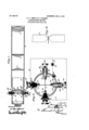
- FIG. 1 is a central longitudinal section of 'such an instrument embodying our improvements.
- Fig. 2 is a transverse-'section thereof on the line 2 2 of Fig. 1
- Fig. 3 is an en trged view of our preferred form of cross- Similar reference-numerals in the several figures indicate similar parts.
- Such devices answer their purpose admirably by day or inviewing bright objects at any time, and at night-it is the custom to illumine them by light admitted from an -extraneous source and properly reflected in the plane in which they lie; but therein lies the objection, as it is manifestly diflicult to direct the rays only upon the point or points of intersection of the lines, and when the object is very faint, either because of its distance or becauseof lack of illumination, or both-as, for instance, at twilight or at night-it is essential that when looking through the telescope the field appear'as dark as possible in order that the faint object may be visible at all.
- 1 indicates the main section of a telescope in which are suitably mounted the objective 2 and the erecting-lenses 3.
- the sliding adjusting-section 4 Fitted within the open end thereof is the sliding adjusting-section 4, provided, preferably, with an adjustablymounted eye ieee 5 and the intermediate field-lens 6 are arranged the cross-hairs 7, which are preferably formed of exceedingly-thin ribbons of a -comparatively Vindestructible material, such as platinum, their greatest width lying IOO inmediately adjacent the latter in a direction longitudinally of the instrument. At their point of intersection each is reduced in the manner shown in Fig.
- a plug 8 preferably of hard rubber or of other material, .properly insulated from the barrel of the telescope and having a longitudinallyadjustable threaded core 9, the inner end of which projects within the tube.
- This inner endl is split to receive one end of the platinum ribbon or cross-hair, which is clamped therein by means of aset-screw 10, while the outer end projects above the lug on the exterior and is provided with a loc -nut 11 and a thumb-nut 12, forming a binding-post for one of the electrical connections.
- the opposite end of the ribbon is similarly secured, by means of a set-screw 13, in the split inner end of a longitudinally-movable in or plunger 14, freely movable centrally oi)a plug 15, threaded in' an alperture in the tube 4 diametrically opposite t 1e plug 8.
- the plug 15 is seated from the interior and of such a length as to project a .threaded portion exteriorly of the tube, upon which is screwed a collar 16.
- the outer end of the plunger 14 is expanded to the approximate internal diameter ofthe collar or other- Wise provided with a shoulder or projection 17, forming an abutment for a light helical spring4 18, the other end of which bears against the end of the plug, normally forcing the plunger outward, and thereby keepingthe cross-hair at a tension, and hencefabsolutely straight, in which position it maybe retained fixed by means of a set-screw 19.
- compensation is made for any slight expansion or stretching that may take place in the ribbon through the eflects 'of heat or from other causes of disarrangement without danger of breakage, as ,the ower of the spring is slight and uniform.
- T 1e other cross-hair is supported in the same manner and at right angles thereto, as above described, the reduced portions bein opposite, or, in other Words, at the point o intersection.
- a single electrical contact A arranged at any point upon the barrel of the telescope, suffices for supplying current'to both of the non-insulated cross-hair supports, Whereat the current divides, traversing each and ⁇ producing thel minute radiations of thedcsiredlntcnsity at the reduced portions, the wider portionsv offering less resistance, and hence remaining unaffected ⁇ W1th the proper voltage.
- current 1s led from the insulatedplugs by means of wires B and C and to the returnwire D and backto the batteryor other source of'supply E. o
- a device for establishing a reference in an optical field the com ination with an optical instrument, of a cross-hair arranged to appear in the field thereof embody- @int ef4 posed of ribbons of conducting material reduced in Width at their point of intersection to enable the said intersecting-points alone to be raised to incandescence by the passage of suitable electrical currents.
Description
110.848.757., Y PATENTED APR. 2, 1901.
yH. c. LOMB E. u. SAILER..
ORIBNTATIUN DEVICE.
APPLIOATION FILED 001229. 19(16.
UNTTED STATES.
PATENT OEEIOE.
HENRY c. LOMB AND ERNEST e. SAILER, OF ROCHESTER, NEW YORK.
ORIENTATION DEVICE.
Specification of Letters' Patent.
Patenten April 2, 1907.
To all whom it may con/cern.:
Be itknown that we, HENRY C. LOMB and ERNEST G. SAILER, both of Rochester, in the county of Monroe and State of New York, have invented certain new and useful Improvements in.Orientation Devices; and we do hereby declare the-following to be a full, clear, and exact `description of the same, reference being had to the accompanying drawings, forming a part of this specification, and to the reference-numerals marked thereon. Our present invention relates to devices for defining a fixed point or-points of reference in the fields of optical instruments, by the aid of which the relative positions of lobjects appearing therein may be determined;
`and it has for its object to provide a device of this nature which is capable of offering such a point in luminous contrast to a clouded or darkened field, whereby the instrument to which it is attached or with which it is used is rendered serviceable with equal efficiency by night or bydayr A further object of our invention is to fur- .nish a point of this character of such minutenes's as will not disturb the line of vision, yet of variable intensity, by means of which adjustments thereof may be made to suit particular conditions.
The construction through which we attain these ends also provides means for bringing the line of observation 'to coincidey with the l optical axis.
To these and other ends the invention consists of certain improvements and combinations of parts, all as will be hereinafter more fully explained, the novel -features being pointed out in the claims at the end of the specification.
While for various optical experiments in many lines, such as astronomical measurements, range-finding, and many kindred pursuits, it is of great importance to obtain a point of reference for the purposes above described, and our improvements lare equally applicable to all, we have illustrated the present form of our device as applied to a telescope of conventional design, and referring to the drawings- Figure 1 is a central longitudinal section of 'such an instrument embodying our improvements. Fig. 2 is a transverse-'section thereof on the line 2 2 of Fig. 1, and Fig. 3 is an en trged view of our preferred form of cross- Similar reference-numerals in the several figures indicate similar parts.
To commandv a point of reference in the field of a telescope, it is usual to extend rtwo very ne lines transversely of the field-lens and at right angles to each other, their intersection being in the optical axis thereof and forming the fixed location of the point' sought. This is accomplished in many instances either by Scratching or drawing faint lines upon the surface of the glass or by Astretching filaments of spider-web or fine wire across its face. Such devices of course answer their purpose admirably by day or inviewing bright objects at any time, and at night-it is the custom to illumine them by light admitted from an -extraneous source and properly reflected in the plane in which they lie; but therein lies the objection, as it is manifestly diflicult to direct the rays only upon the point or points of intersection of the lines, and when the object is very faint, either because of its distance or becauseof lack of illumination, or both-as, for instance, at twilight or at night-it is essential that when looking through the telescope the field appear'as dark as possible in order that the faint object may be visible at all. To overcome .these defects, we construct the filaments of a material which is an electrical conductor, reducing the area of their crosssections at the points of intersection and connecting each with a source of current-supply, whereby the greater resistance offered by Said tent alone to glow, the radiations emitted being directly governable by the intensity of the current. Y
Referring now to the drawings, 1 indicates the main section of a telescope in which are suitably mounted the objective 2 and the erecting-lenses 3. Fitted within the open end thereof is the sliding adjusting-section 4, provided, preferably, with an adjustablymounted eye ieee 5 and the intermediate field-lens 6 are arranged the cross-hairs 7, which are preferably formed of exceedingly-thin ribbons of a -comparatively Vindestructible material, such as platinum, their greatest width lying IOO inmediately adjacent the latter in a direction longitudinally of the instrument. At their point of intersection each is reduced in the manner shown in Fig. 3 to theminimum cross-sectional area, which is yet sufficient to withstand the slight tensile strain imposed by the su portin devices hereinafter described, and t lough c osely apreaching each other at this point they are iield vapart and out of contact. As each rib- -bon and its su porting connections is herein shown to be i entical in construction, a descri tion of one will suffice for both.
'l eaded into an aperture in the tube 4 in front of the lens-6 is a plug 8, preferably of hard rubber or of other material, .properly insulated from the barrel of the telescope and having a longitudinallyadjustable threaded core 9, the inner end of which projects within the tube. This inner endl is split to receive one end of the platinum ribbon or cross-hair, which is clamped therein by means of aset-screw 10, while the outer end projects above the lug on the exterior and is provided with a loc -nut 11 and a thumb-nut 12, forming a binding-post for one of the electrical connections. The opposite end of the ribbon is similarly secured, by means of a set-screw 13, in the split inner end of a longitudinally-movable in or plunger 14, freely movable centrally oi)a plug 15, threaded in' an alperture in the tube 4 diametrically opposite t 1e plug 8. The plug 15 is seated from the interior and of such a length as to project a .threaded portion exteriorly of the tube, upon which is screwed a collar 16. AThe outer end of the plunger 14 is expanded to the approximate internal diameter ofthe collar or other- Wise provided with a shoulder or projection 17, forming an abutment for a light helical spring4 18, the other end of which bears against the end of the plug, normally forcing the plunger outward, and thereby keepingthe cross-hair at a tension, and hencefabsolutely straight, in which position it maybe retained fixed by means of a set-screw 19. In this manner compensation is made for any slight expansion or stretching that may take place in the ribbon through the eflects 'of heat or from other causes of disarrangement without danger of breakage, as ,the ower of the spring is slight and uniform. T 1e other cross-hair is supported in the same manner and at right angles thereto, as above described, the reduced portions bein opposite, or, in other Words, at the point o intersection. A single electrical contact A, arranged at any point upon the barrel of the telescope, suffices for supplying current'to both of the non-insulated cross-hair supports, Whereat the current divides, traversing each and `producing thel minute radiations of thedcsiredlntcnsity at the reduced portions, the wider portionsv offering less resistance, and hence remaining unaffected `W1th the proper voltage. current 1s thence led from the insulatedplugs by means of wires B and C and to the returnwire D and backto the batteryor other source of'supply E. o The Widti of the cross-hairs used'gives rise to another feature of our invention, as
The
when adjusted to lie in planes common with the axes of the lens by proper tests they form a guide to the eye by means of which the line ofvision is directed in the line of the o tical axis. This positionis reached Whent e edges of the cross-.hairs appear of a minimum thickness, as any deviation in a perpendicular or lateral direction would make itself ap )arent by exposing the wide surfaces of the ribbons conver ing in nonarallelism to the direction of t e light. or accomplishing the adjustments here spoken of the plunger 14 is fitted upon its exterior end with a tlnunb-nut 20, by means of which it is rotated to exert a torsional influence upon the ribbons. 1
It will be understood that many forms of cross-hairs maybe used to accomplish the results described Without departing from the spirit of our invention, or the charging ofl only one of the two intersecting hairs may be found sul licient for many purposes in any or all of the various uses to which our improvements are applicable, or, in like manner, sev- -eral pairs or couples may be used when it is desired, for instance, to arrange a number of points for establishing a definite field of astronomical observation.
An instrument of the class described While I equally efficient by day in respect to the ordinary devices is of the greatest service at night or under the usually adverse circumstances mentioned, furnishing a point of exceeding minuteness and of'adjustable intensity without ini any way interfering with the clearness of the vision\` We claim as our invention- 1.. In a device for establishing a luminous' lbination with an optical instrument, of a cross-hair arranged to appear in the field thereof embodying an electrical conductingfilament reduced in the area of its cross-section at a point intermediate its ends and an electrical circuit including said filament.
3. vThe combination with an optical instrunient, of cross-hairs arranged therein corn- IIO posed of electrical conducting material and adapted to be rendered luminous at their point offintersection alone, by the passage of an electric current through them.
4. In adevice for establishing a reference in an optical field, the com ination with an optical instrument, of a cross-hair arranged to appear in the field thereof embody- @int ef4 posed of ribbons of conducting material reduced in Width at their point of intersection to enable the said intersecting-points alone to be raised to incandescence by the passage of suitable electrical currents.
7. In an appliance for establishing'a oint Y Y of reference 1n an optical field, the com inazoA tion withv a -support-and a cross-hair connectedthereto at one end, of a plug in the support, a lunger o erating therein and con-- nected to t e opposite-end of the cross-hair,
a shoulder on the plunger and a spring arranged on the su' port and engaging the shoulderon lthe pllilnger to hold the crosshair under tension.
' 8. In an electrically-illuminated crosshair for optical instruments, the Acombination with a tubular support of electrical conducting material inclosing a ilament in contact therewith at one end, of an insulated plug arranged in said support having a Inetallic core connected to the vfilament at one 10. The combination With an optical in- Y strument embodyin a lens, of. 'two crosshairs composed of ri bons of suitable material arranged transversely at right .angles to the opticalaxis and to eachother with their greatest transverse dimension extending in the direction of said axis, whereby Vthe. observin organ may be` alined With reference to the atter. i
11. The combination with an optical instrument embodyin a lens, of tWo crosshairs composed of ri bons of suitable material arran ed transversely atlright angles to the optica axis and toy each other with their greatest transverse dimension extending in the direction of said axis, and means for efflecting a torsional adjustment of the crossairs. n
HENRY C. LOMB. ERNEST Gr. SAILER.
Witnesses: A K RUSSELL B.. GRIFFITH,
CLARENCE A. BATEMAN.
Priority Applications (1)
| Application Number | Priority Date | Filing Date | Title |
|---|---|---|---|
| US34095806A US848757A (en) | 1906-10-29 | 1906-10-29 | Orientation device. |
Applications Claiming Priority (1)
| Application Number | Priority Date | Filing Date | Title |
|---|---|---|---|
| US34095806A US848757A (en) | 1906-10-29 | 1906-10-29 | Orientation device. |
Publications (1)
| Publication Number | Publication Date |
|---|---|
| US848757A true US848757A (en) | 1907-04-02 |
Family
ID=2917219
Family Applications (1)
| Application Number | Title | Priority Date | Filing Date |
|---|---|---|---|
| US34095806A Expired - Lifetime US848757A (en) | 1906-10-29 | 1906-10-29 | Orientation device. |
Country Status (1)
| Country | Link |
|---|---|
| US (1) | US848757A (en) |
Cited By (8)
| Publication number | Priority date | Publication date | Assignee | Title |
|---|---|---|---|---|
| US2418264A (en) * | 1944-07-05 | 1947-04-01 | John E Norman | Driftmeter |
| US2496045A (en) * | 1946-12-06 | 1950-01-31 | Thomas L Ford | Telescopic sight |
| US2766038A (en) * | 1950-08-03 | 1956-10-09 | Continental Scale Corp | Scale |
| US2807981A (en) * | 1955-03-14 | 1957-10-01 | Eastman Kodak Co | Sighting telescope |
| US2909838A (en) * | 1956-10-04 | 1959-10-27 | Kollmorgen Optical Corp | Hot-wire reticule |
| US3184854A (en) * | 1961-01-10 | 1965-05-25 | Fairchild Hiller Corp | Position plotter |
| US3286352A (en) * | 1964-04-20 | 1966-11-22 | Leupold & Stevens Instr Inc | Reticle for a sighting instrument |
| US3394461A (en) * | 1966-03-17 | 1968-07-30 | Robert S. Thomas | Reticle construction |
-
1906
- 1906-10-29 US US34095806A patent/US848757A/en not_active Expired - Lifetime
Cited By (8)
| Publication number | Priority date | Publication date | Assignee | Title |
|---|---|---|---|---|
| US2418264A (en) * | 1944-07-05 | 1947-04-01 | John E Norman | Driftmeter |
| US2496045A (en) * | 1946-12-06 | 1950-01-31 | Thomas L Ford | Telescopic sight |
| US2766038A (en) * | 1950-08-03 | 1956-10-09 | Continental Scale Corp | Scale |
| US2807981A (en) * | 1955-03-14 | 1957-10-01 | Eastman Kodak Co | Sighting telescope |
| US2909838A (en) * | 1956-10-04 | 1959-10-27 | Kollmorgen Optical Corp | Hot-wire reticule |
| US3184854A (en) * | 1961-01-10 | 1965-05-25 | Fairchild Hiller Corp | Position plotter |
| US3286352A (en) * | 1964-04-20 | 1966-11-22 | Leupold & Stevens Instr Inc | Reticle for a sighting instrument |
| US3394461A (en) * | 1966-03-17 | 1968-07-30 | Robert S. Thomas | Reticle construction |
Similar Documents
| Publication | Publication Date | Title |
|---|---|---|
| US848757A (en) | Orientation device. | |
| US1246338A (en) | Illuminated transparent retractor. | |
| US2367858A (en) | Illuminated instrument | |
| US1931552A (en) | Illuminated telescope sight | |
| US2240402A (en) | Illuminated microscope | |
| GB1241284A (en) | Improvements relating to microscopes | |
| US2104198A (en) | Magnifying and illuminating device | |
| US2087081A (en) | Optical magnifying apparatus | |
| US2297799A (en) | Viewing device | |
| US2559698A (en) | Stereoscopic magnifier | |
| US2909838A (en) | Hot-wire reticule | |
| US2098702A (en) | Diagnostic instrument | |
| US2365104A (en) | Diagnostic instrument | |
| US1753614A (en) | Flash light attachment | |
| US1804151A (en) | Retinoscope | |
| US1960114A (en) | Illuminating magnifying glass | |
| US4157209A (en) | Optical device having light-mixing element | |
| US2828669A (en) | Lens system for endoscopes | |
| US2234430A (en) | Galvanometer | |
| US728589A (en) | Surgical instrument. | |
| US1570623A (en) | Diagnostic instrument | |
| US1675158A (en) | Attachment for abney levels | |
| US1162058A (en) | Optical testing instrument. | |
| US1376666A (en) | Optical pyrometry | |
| US1560864A (en) | Optical pyrometer or similar instrument |