US8479359B2 - Hinge device, method of redirecting load applied to hinge device, and mobile terminal apparatus - Google Patents

Hinge device, method of redirecting load applied to hinge device, and mobile terminal apparatus Download PDF

Info

Publication number
US8479359B2
US8479359B2 US12/431,257 US43125709A US8479359B2 US 8479359 B2 US8479359 B2 US 8479359B2 US 43125709 A US43125709 A US 43125709A US 8479359 B2 US8479359 B2 US 8479359B2
Authority
US
United States
Prior art keywords
stopper
frame member
receiving portion
shaft
contact
Prior art date
Legal status (The legal status is an assumption and is not a legal conclusion. Google has not performed a legal analysis and makes no representation as to the accuracy of the status listed.)
Expired - Fee Related, expires
Application number
US12/431,257
Other versions
US20090293231A1 (en
Inventor
Osamu Yabe
Yuichi Yamada
Tomoyuki SONODA
Current Assignee (The listed assignees may be inaccurate. Google has not performed a legal analysis and makes no representation or warranty as to the accuracy of the list.)
Sony Corp
Original Assignee
Sony Corp
Sony Mobile Communications Inc
Priority date (The priority date is an assumption and is not a legal conclusion. Google has not performed a legal analysis and makes no representation as to the accuracy of the date listed.)
Filing date
Publication date
Application filed by Sony Corp, Sony Mobile Communications Inc filed Critical Sony Corp
Assigned to SONY ERICSSON MOBILE COMMUNICATIONS JAPAN, INC. reassignment SONY ERICSSON MOBILE COMMUNICATIONS JAPAN, INC. ASSIGNMENT OF ASSIGNORS INTEREST (SEE DOCUMENT FOR DETAILS). Assignors: Sonoda, Tomoyuki, YABE, OSAMU, YAMADA, YUICHI
Publication of US20090293231A1 publication Critical patent/US20090293231A1/en
Assigned to Sony Mobile Communications Japan, Inc. reassignment Sony Mobile Communications Japan, Inc. CHANGE OF NAME (SEE DOCUMENT FOR DETAILS). Assignors: SONY ERICSSON MOBILE COMMUNICATIONS JAPAN, INC.
Assigned to SONY CORPORATION reassignment SONY CORPORATION ASSIGNMENT OF PARTIAL RIGHTS Assignors: Sony Mobile Communications Inc.
Assigned to Sony Mobile Communications Inc. reassignment Sony Mobile Communications Inc. CHANGE OF NAME (SEE DOCUMENT FOR DETAILS). Assignors: Sony Mobile Communications Japan, Inc.
Application granted granted Critical
Publication of US8479359B2 publication Critical patent/US8479359B2/en
Expired - Fee Related legal-status Critical Current
Adjusted expiration legal-status Critical

Links

Images

Classifications

    • HELECTRICITY
    • H04ELECTRIC COMMUNICATION TECHNIQUE
    • H04BTRANSMISSION
    • H04B1/00Details of transmission systems, not covered by a single one of groups H04B3/00 - H04B13/00; Details of transmission systems not characterised by the medium used for transmission
    • H04B1/38Transceivers, i.e. devices in which transmitter and receiver form a structural unit and in which at least one part is used for functions of transmitting and receiving
    • HELECTRICITY
    • H04ELECTRIC COMMUNICATION TECHNIQUE
    • H04MTELEPHONIC COMMUNICATION
    • H04M1/00Substation equipment, e.g. for use by subscribers
    • H04M1/02Constructional features of telephone sets
    • H04M1/0202Portable telephone sets, e.g. cordless phones, mobile phones or bar type handsets
    • H04M1/0206Portable telephones comprising a plurality of mechanically joined movable body parts, e.g. hinged housings
    • H04M1/0208Portable telephones comprising a plurality of mechanically joined movable body parts, e.g. hinged housings characterized by the relative motions of the body parts
    • H04M1/0214Foldable telephones, i.e. with body parts pivoting to an open position around an axis parallel to the plane they define in closed position
    • H04M1/0216Foldable in one direction, i.e. using a one degree of freedom hinge
    • HELECTRICITY
    • H04ELECTRIC COMMUNICATION TECHNIQUE
    • H04MTELEPHONIC COMMUNICATION
    • H04M1/00Substation equipment, e.g. for use by subscribers
    • H04M1/02Constructional features of telephone sets
    • HELECTRICITY
    • H04ELECTRIC COMMUNICATION TECHNIQUE
    • H04WWIRELESS COMMUNICATION NETWORKS
    • H04W88/00Devices specially adapted for wireless communication networks, e.g. terminals, base stations or access point devices
    • H04W88/02Terminal devices
    • HELECTRICITY
    • H04ELECTRIC COMMUNICATION TECHNIQUE
    • H04MTELEPHONIC COMMUNICATION
    • H04M1/00Substation equipment, e.g. for use by subscribers
    • H04M1/02Constructional features of telephone sets
    • H04M1/18Telephone sets specially adapted for use in ships, mines, or other places exposed to adverse environment
    • H04M1/185Improving the rigidity of the casing or resistance to shocks

Definitions

  • the present invention relates to hinge devices suitable for application to apparatuses, such as a mobile phone, a personal handyphone system (PHS), a personal digital assistant (PDA), a portable game machine, and a notebook personal computer, each including two bodies connected to each other with a hinge so as to be openable and foldable together, and also relates to methods of redirecting loads applied to the hinge devices, and to mobile terminal apparatuses.
  • apparatuses such as a mobile phone, a personal handyphone system (PHS), a personal digital assistant (PDA), a portable game machine, and a notebook personal computer, each including two bodies connected to each other with a hinge so as to be openable and foldable together, and also relates to methods of redirecting loads applied to the hinge devices, and to mobile terminal apparatuses.
  • the present invention relates to a hinge device including a stopper and a stopper-receiving portion that are configured such that a load produced upon contact therebetween when the two bodies are opened is redirected in such a direction that the thickness of the stopper becomes larger, whereby the strength of the hinge device is increased, and also relates to a method of redirecting the load applied to the hinge device, and to a mobile terminal apparatus.
  • a typical foldable mobile phone includes an upper body and a lower body that are connected to each other with a hinge device and are thus openable and foldable together.
  • a hinge device enabling the upper body and the lower body to be opened and folded together is integrally provided with the two bodies.
  • Such a hinge device provided as a portion of the two bodies in terms of design and shape, may limit the designs and shapes of the upper and lower bodies.
  • frame hinge device which is provided separately from the upper body and the lower body.
  • the frame hinge device which is a separate body from the upper and lower bodies, the shapes of the upper and lower bodies can be designed substantially freely and with more ease.
  • the frame hinge device includes a first hinge member and a second hinge member.
  • the first hinge member is secured to the upper body
  • the second hinge member is secured to the lower body, whereby the upper and lower bodies are openable and foldable together.
  • the frame hinge device includes a stopper so that the rotation angle formed between the upper body and the lower body is regulated to be the maximum immediately before the upper body and the lower body, when opened, come into contact with each other.
  • a stopper is easily damaged by, for example, an impact caused by dropping the phone and excessive opening of the phone. Therefore, in a product development process, developers make special efforts to provide sufficient strength to the stopper.
  • Japanese Unexamined Patent Application Publication No. 2006-118178 discloses a biaxial hinge that is not easily damaged and whose stopper is prevented from coming off a turning-movement shaft even if the sizes of the turning-movement shaft and the stopper are reduced.
  • the stopper and the turning-movement shaft are formed as an integral body, and the turning-movement shaft included in the integral body is attached to an opening/closing-movement shaft.
  • the turning-movement shaft is prevented from turning beyond the critical angle by causing a projection provided on the stopper to be locked by a locking portion of the opening/closing-movement shaft.
  • the turning-movement shaft and the stopper are provided as an integral body, sufficient strength can be provided to the stopper and the joint between the stopper and the turning-movement shaft. In addition, coming off of the stopper and damage to the stopper can be prevented from occurring while the turning-movement shaft is turned.
  • Bodies of earlier mobile phones are large, and therefore hinges thereof are also large, with large stoppers assuredly providing sufficient strength.
  • recent mobile phones have smaller sizes and smaller thicknesses, and naturally hinge devices thereof are provided in smaller sizes.
  • a hinge device of a small size has a small shaft diameter. Therefore, according to the principle of leverage, a force applied to the stopper when the upper and lower bodies are rotated increases, leading to a problem in that the stopper may be damaged easily.
  • FIGS. 22A and 22B show an example of such a case.
  • a stopper 100 of a first hinge member secured to the upper body comes into contact with a stopper 101 of a second hinge member secured to the lower body.
  • the rotation angle formed between the upper and lower bodies is regulated to be the maximum at the predetermined angle of, for example, 170 degrees.
  • the stopper 100 of the first hinge member and the stopper 101 of the second hinge member are configured such that the stopper 101 of the second hinge member vertically comes into contact with and supports the stopper 100 of the first hinge member. Therefore, when the stopper 100 of the first hinge member comes into contact with the stopper 101 of the second hinge member, a force is applied to the stopper 100 of the first hinge member in directions indicated by dashed arrows shown in FIGS. 22A and 22B , i.e., the direction in which the stopper 101 comes into contact with the stopper 100 .
  • the force in such a direction significantly affects a corner 100 c of the stopper 100 of the first hinge member shown in FIGS. 22A and 22B , that is, a large load is applied to the corner 100 c . Therefore, if some large force is applied to the hinge device because of, for example, an impact caused by dropping the phone or excessive opening of the phone, the stopper 100 of the first hinge member may be damaged from the corner 100 c thereof.
  • a large stopper may alternatively be used.
  • use of a large stopper naturally increases the size of the hinge device, against the trend of recent mobile phones having smaller sizes and smaller thicknesses.
  • the present invention provide a hinge device that can be manufactured with low cost from materials suitable for mass production and have strength sufficient for preventing damage to a stopper occurring when a large force is applied thereto even if the size of the hinge device is reduced, and also provide a method of redirecting the load applied to the hinge device, and a mobile terminal apparatus.
  • a hinge device includes a first frame member having a securing section at which the first frame member is secured to a first body, a rotation shaft supporting the first frame member allowing rotation thereof, a stopper provided on the first frame member in such a manner as to project in a direction in which the rotation shaft extends and to rotate together with the first frame member about the rotation shaft, and a second frame member.
  • the second frame member has a securing section at which the second frame member is secured to a second body, a rotation-shaft-supporting section supporting the rotation shaft, and a stopper-receiving portion receiving the stopper.
  • the stopper and the stopper-receiving portion are subjected to load-redirecting processing such that a load produced upon contact between the stopper and the stopper-receiving portion is applied in such a direction that a thickness of the stopper becomes larger.
  • a load produced upon contact between the stopper and the stopper-receiving portion can be redirected in such a direction that the thickness of the stopper becomes larger. Therefore, the stopper can be prevented from being damaged by the aforementioned load.
  • the hinge device can be manufactured from inexpensive materials suitable for mass production and have strength sufficient for preventing the stopper from being damaged because of an impact caused by dropping an apparatus including the hinge device and excessive opening of the apparatus even if the size of the hinge device is reduced.
  • FIG. 1 is a front view of a mobile phone, in an open state, according to an embodiment of the present invention
  • FIG. 2 is an exploded perspective view of a hinge device included in the mobile phone according to the embodiment
  • FIG. 3 is a perspective view of a first frame member included in the hinge device
  • FIG. 4 is another perspective view of the first frame member included in the hinge device
  • FIG. 5 is a diagram showing a one-end surface of a first shaft-insertion section included in the first frame member
  • FIG. 6 is a perspective view of the first shaft-insertion section, seen from the side of the one-end surface, with a cam member fitted thereto;
  • FIG. 7 is a perspective view of another cam member provided on a rotation support section and to which the cam member provided on the first shaft-insertion section is fitted;
  • FIG. 8 is an enlarged view of a first stopper provided on the first shaft-insertion section of the first frame member
  • FIG. 9 is a perspective view for describing how the first stopper is made to slope
  • FIG. 10 is a perspective view for describing a radius given to a junction between the first stopper and the first shaft-insertion section;
  • FIG. 11 is an enlarged perspective view of the first stopper provided on the first shaft-insertion section of the first frame member
  • FIG. 12 is an enlarged view of a second stopper provided on a second shaft-insertion section of the first frame member
  • FIG. 13 is a perspective view for describing how the second stopper is made to slope
  • FIG. 14 is a perspective view of a second frame member included in the hinge device.
  • FIG. 15 is another perspective view of the second frame member included in the hinge device.
  • FIG. 16 is a diagram for describing a first-stopper-receiving portion provided on the second frame member
  • FIG. 17 is an enlarged view of the first-stopper-receiving portion provided on the second frame member
  • FIG. 18 is a diagram for describing a second-stopper-receiving portion provided on the second frame member
  • FIG. 19 is an enlarged view of the second-stopper-receiving portion provided on the second frame member
  • FIG. 20 is a diagram for describing sloping directions of the first-stopper-receiving portion and the second-stopper-receiving portion;
  • FIGS. 21A and 21B are diagrams for describing a function of redirecting a load applied to the hinge device.
  • FIGS. 22A and 22B are diagrams for describing how a load is applied to a related-art hinge device.
  • FIG. 1 is a front view of a mobile phone, in an open state, according to an embodiment of the present invention.
  • the mobile phone of the embodiment includes a substantially rectangular upper body 50 and a substantially rectangular lower body 51 having substantially the same size as the upper body 50 .
  • One short-side end of the upper body 50 and one short-side end of the lower body 51 are connected to each other with a hinge device 52 interposed therebetween, whereby the upper body 50 and the lower body 51 can be folded together (closed) and opened.
  • the upper body 50 is provided with a main display unit 53 including a liquid crystal display or the like, a speaker unit 54 configured to output audio that is received, a so-called self-shooting camera unit 55 configured to shoot an image of a user of the mobile phone when, for example, a videophone function is used, and a television antenna 56 configured to receive television broadcast.
  • the upper body 50 is also provided with a sub-display unit (not shown), having a small display screen, on the side opposite the side having the main display unit 53 .
  • the lower body 51 is provided with a key operation unit 57 including various operation keys such as a directional key pad, number keys, an on-hook key, an off-hook key, and so forth, and a microphone unit 58 configured to collect audio to be sent.
  • the lower body 51 is also provided with a camera unit (not shown) configured to shoot an image of a desired object and a stereo speaker unit (not shown) for external output, on the side opposite the side having the key operation unit 57 .
  • FIG. 2 is an exploded perspective view of the hinge device 52 included in the mobile phone according to the embodiment of the present invention.
  • the hinge device 52 according to the embodiment includes a first frame member 2 having a securing section 1 in which screw holes are provided for screwing the first frame member 2 to the upper body 50 of the mobile phone, a second frame member 4 having a securing section 3 at which the second frame member 4 is screwed to the lower body 51 of the mobile phone, and a shaft member 5 having a substantially cylindrical stick-like shape and serving as a rotational axis about which the first and second frame members 2 and 4 rotate.
  • the first and second frame members 2 and 4 are made of curable plastic material such as acrylonitrile butadiene styrene (ABS) resin.
  • the shaft member 5 is made of metal material such as aluminum or iron.
  • FIGS. 3 and 4 are perspective views of the first frame member 2 .
  • the first frame member 2 includes a first shaft-insertion section 6 and a second shaft-insertion section 7 that have substantially cylindrical shapes and whose respective one-end surface 6 a and one-end surface 7 a face each other with the securing section 1 interposed therebetween.
  • the first and second shaft-insertion sections 6 and 7 have shaft-insertion holes 8 and 9 , respectively, passing from the respective centers of the one-end surfaces 6 a and 7 a through to the respective centers of the other-end surfaces 6 b and 7 b .
  • the first frame member 2 (and the upper body 50 secured thereto) is supported in such a manner as to be rotatable about the shaft member 5 , i.e., the rotational axis.
  • FIG. 5 is a front view of the one-end surface 6 a of the first shaft-insertion section 6 .
  • the first shaft-insertion section 6 has therein a spring-receiving portion 11 that receives a spring 10 shown in FIG. 2 . Therefore, the diameter of the first shaft-insertion section 6 is larger than that of the second shaft-insertion section 7 .
  • the one-end surface 6 a of the first shaft-insertion section 6 has a pair of recesses 18 a and 18 b on opposite sides of the shaft-insertion hole 8 .
  • a pair of projections 12 a and 12 b provided on a cam member 12 which is urged by the spring 10 , are to be fitted into and secured by the recesses 18 a and 18 b , respectively.
  • the projections 12 a and 12 b of the cam member 12 are to be fitted into recesses 30 a and 30 b, respectively, of a cam member 30 secured at one end 15 a of a rotation-shaft-supporting section 15 of the second frame member 4 .
  • the projections 12 a and 12 b of the cam member 12 shown in FIG. 6 fall into or come out of the recesses 30 a and 30 b of the cam member 30 shown in FIG. 7 , whereby tactile clicking sensation is provided.
  • the first shaft-insertion section 6 has on the one-end surface 6 a thereof a first stopper 13 projecting in a direction in which the shaft member 5 , serving as the rotational axis, extends.
  • the first stopper 13 has a thickness ranging from the outer periphery of the first shaft-insertion section 6 to the periphery of the shaft-insertion hole 8 , and extends on the one-end surface 6 a with a length of about 1 ⁇ 4 of the circumference of the first shaft-insertion section 6 .
  • FIG. 8 is an enlarged view of the first stopper 13 .
  • FIGS. 9 to 11 are perspective views of the first shaft-insertion section 6 .
  • a junction corner 13 a which is a corner (junction) between the first stopper 13 and the first shaft-insertion section 6 , is given a radius such that the first stopper 13 and the first shaft-insertion section 6 are connected with a predetermined curve, not with a sharp turn, therebetween.
  • the first stopper 13 has a contact surface 13 b that is to be in contact with a first-stopper-receiving portion 16 (shown in FIG. 17 ), which will be described below.
  • the contact surface 13 b is made to slope at an angle in the direction of the periphery of the first stopper 13 , as shown in FIG. 5 , and at a predetermined angle with respect to the rotational axis, as shown in FIG. 9 .
  • such sloping of the contact surface 13 b of the first stopper 13 is intended to redirect a load produced upon contact between the first stopper 13 of the first shaft-insertion section 6 and the first-stopper-receiving portion 16 (see FIG. 17 ), in such a direction that the thickness of the first-stopper-receiving portion 16 becomes larger.
  • the contact surface 13 b of the first stopper 13 is made to slope such that a load produced upon contact between the first stopper 13 of the first shaft-insertion section 6 and the first-stopper-receiving portion 16 is applied to the first-stopper-receiving portion 16 in such a direction that the thickness of the first-stopper-receiving portion 16 becomes larger.
  • the second shaft-insertion section 7 has on the one-end surface 7 a thereof a second stopper 14 , having substantially the same configuration as the first stopper 13 on the one-end surface 6 a of the first shaft-insertion section 6 .
  • the second stopper 14 projects in the direction in which the shaft member 5 , serving as the rotational axis, extends.
  • the second stopper 14 has a thickness ranging from the outer periphery of the second shaft-insertion section 7 to the periphery of the shaft-insertion hole 9 , and extends on the one-end surface 7 a with a length of about 1 ⁇ 4 of the circumference of the second shaft-insertion section 7 .
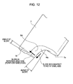
  • FIG. 12 is an enlarged view of the second stopper 14 .
  • FIG. 13 is a perspective view of the second stopper 14 .
  • a junction corner 14 a which is a corner (junction) between the second stopper 14 and the second shaft-insertion section 7 , is given a radius such that the second stopper 14 and the second shaft-insertion section 7 are connected with a predetermined curve, not with a sharp turn, therebetween.
  • the second stopper 14 has a contact surface 14 b that is to be in contact with a second-stopper-receiving portion 17 (shown in FIG. 18 ), which will be described below.
  • the contact surface 14 b is made to slope at an angle in the direction of the periphery of the second stopper 14 and at a predetermined angle with respect to the rotational axis.
  • such sloping of the contact surface 14 b of the second stopper 14 is intended to redirect a load produced upon contact between the second stopper 14 of the second shaft-insertion section 7 and the second-stopper-receiving portion 17 (see FIG. 18 ), in such a direction that the thickness of the second-stopper-receiving portion 17 becomes larger.
  • the contact surface 14 b of the second stopper 14 is made to slope such that a load produced upon contact between the second stopper 14 of the second shaft-insertion section 7 and the second-stopper-receiving portion 17 is applied to the second-stopper-receiving portion 17 in such a direction that the thickness of the second-stopper-receiving portion 17 becomes larger.
  • FIGS. 14 and 15 are perspective views of the second frame member 4 .
  • the second frame member 4 includes the rotation-shaft-supporting section 15 having substantially a cylindrical shape and configured to support the shaft member 5 , the first-stopper-receiving portion 16 provided near the one end 15 a of the rotation-shaft-supporting section 15 , and the second-stopper-receiving portion 17 provided near the other end 15 b of the rotation-shaft-supporting section 15 .
  • the rotation-shaft-supporting section 15 , the first-stopper-receiving portion 16 , and the second-stopper-receiving portion 17 are made of curable plastic material, such as ABS resin, and are integrally molded with the securing section 3 .
  • the rotation-shaft-supporting section 15 has a shaft-insertion hole 18 passing from the one end 15 a through to the other end 15 b .
  • the rotation-shaft-supporting section 15 supports the shaft member 5 , serving as the rotational axis, inserted into the shaft-insertion hole 18 .
  • FIG. 16 is a perspective view of the first-stopper-receiving portion 16 .
  • FIG. 17 is an enlarged view of the first-stopper-receiving portion 16 .
  • an edge 16 a of the first-stopper-receiving portion 16 is given such a radius as to form a predetermined curve.
  • the radius given to the edge 16 a of the first-stopper-receiving portion 16 corresponds to the radius given to the junction corner 13 a of the first stopper 13 . Therefore, the first stopper 13 and the first-stopper-receiving portion 16 are to be in contact with each other at the junction corner 13 a and the edge 16 a forming curves.
  • the first-stopper-receiving portion 16 has a contact surface 16 b that is to be in contact with the contact surface 13 b of the first stopper 13 shown in FIGS. 9 and 10 .
  • the contact surface 16 b is cut obliquely such that an end thereof near the edge 16 a resides lower than the opposite end thereof away from the edge 16 a, whereby the contact surface 16 b is made to slope at an angle with respect to the rotational axis.
  • the contact surface 16 b of the first-stopper-receiving portion 16 is made to slope at another angle in the rotating direction of the rotational axis, as shown in FIG. 17 .
  • the contact surface 16 b is made to slope such that an end thereof near the rotational axis resides lower than the opposite end thereof away from the rotational axis.
  • the contact surface 16 b is made to slope at an angle with respect to the rotational axis and at another angle in the rotating direction.
  • the contact surface 16 b of the first-stopper-receiving portion 16 is made to slope such that a load produced upon contact between the first stopper 13 of the first shaft-insertion section 6 and the contact surface 16 b is applied in such a direction that the thickness of the first shaft-insertion section 6 becomes larger.
  • the rotation angle of the hinge device 52 i.e., the rotation angle formed between the upper body 50 and the lower body 51 , is regulated to be the maximum at an angle of, for example, 170 degrees.
  • the second-stopper-receiving portion 17 is also given a radius and is made to slope in substantially the same manner as in the case of the first-stopper-receiving portion 16 .
  • FIG. 18 is a perspective view of the second-stopper-receiving portion 17 .
  • FIG. 19 is an enlarged view of the second-stopper-receiving portion 17 .
  • an edge 17 a of the second-stopper-receiving portion 17 is given such a radius as to form a predetermined curve.
  • the radius given to the edge 17 a of the second-stopper-receiving portion 17 corresponds to the radius given to the junction corner 14 a of the second stopper 14 . Therefore, the second stopper 14 and the second-stopper-receiving portion 17 are to be in contact with each other at the junction corner 14 a and the edge 17 a forming curves.
  • the second-stopper-receiving portion 17 has a contact surface 17 b that is to be in contact with the contact surface 14 b of the second stopper 14 shown in FIGS. 12 and 13 .
  • the contact surface 17 b is cut obliquely such that an end thereof near the edge 17 a resides lower than the opposite end thereof away from the edge 17 a, whereby the contact surface 17 b is made to slope at an angle with respect to the rotational axis.
  • the contact surface 17 b of the second-stopper-receiving portion 17 is made to slope at another angle in the rotating direction of the rotational axis, as shown in FIG. 19 .
  • the contact surface 17 b is made to slope such that the contact surface 17 b descends in a direction from an open-position side to a closed-position side.
  • the contact surface 17 b is made to slope at an angle with respect to the rotational axis and at another angle in the rotating direction.
  • the contact surface 17 b of the second-stopper-receiving portion 17 is made to slope such that a load produced upon contact between the second stopper 14 of the second shaft-insertion section 7 and the contact surface 17 b is applied in such a direction that the thickness of the second shaft-insertion section 7 becomes larger.
  • the rotation angle of the hinge device 52 i.e., the rotation angle formed between the upper body 50 and the lower body 51 , is regulated to be the maximum at an angle of, for example, 170 degrees.
  • FIG. 20 shows the sloping directions of the contact surface 16 b of the first-stopper-receiving portion 16 and the sloping directions of the contact surface 17 b of the second-stopper-receiving portion 17 .
  • bold arrows indicate the sloping directions of the contact surfaces 16 b and 17 b .
  • the contact surface 16 b and the contact surface 17 b are made to slope at angles with respect to the rotational axis, in diverging directions. Further, the contact surface 16 b and the contact surface 17 b are made to slope at angles in the rotating direction in such a manner as to descend in a direction from the open-position side to the closed-position side.
  • the first stopper 13 of the first shaft-insertion section 6 and the second stopper 14 of the second shaft-insertion section 7 that are to be in contact with the contact surface 16 b and the contact surface 17 b, respectively, are made to slope in correspondence with the contact surface 16 b and the contact surface 17 b, respectively.
  • the spring 10 is inserted into the spring-receiving portion 11 (refer to FIG. 5 ) provided in the first shaft-insertion section 6 of the first frame member 2 .
  • the projections 12 a and 12 b of the cam member 12 are fitted into the recesses 18 a and 18 b provided in the one-end surface 6 a of the first shaft-insertion section 6 .
  • the cam member 30 into which the projections 12 a and 12 b of the cam member 12 are to be fitted is fixed to the rotation-shaft-supporting section 15 .
  • the one-end surface 6 a of the first shaft-insertion section 6 of the first frame member 2 is brought to face the one end 15 a of the rotation-shaft-supporting section 15 of the second frame member 4
  • the one-end surface 7 a of the second shaft-insertion section 7 of the first frame member 2 is brought to face the other end 15 b of the rotation-shaft-supporting section 15 of the second frame member 4 , whereby the first frame member 2 is fitted to the second frame member 4 .
  • a washer 19 is placed between a stationary cam member 20 , provided on the second frame member 4 , and the first shaft-insertion section 6 . Then, the shaft member 5 is inserted into the stationary cam member 20 , the shaft-insertion hole 8 provided in the first shaft-insertion section 6 of the first frame member 2 , the shaft-insertion hole 18 provided in the rotation-shaft-supporting section 15 of the second frame member 4 , and the shaft-insertion hole 9 provided in the second shaft-insertion section 7 of the first frame member 2 , in that order. Lastly, a washer stopper 21 is attached to the stationary cam member 20 so that the shaft member 5 is fixed to the stationary cam member 20 . Thus, the process of assembling the hinge device 52 is completed.
  • the first stopper 13 provided on the first shaft-insertion section 6 of the first frame member 2 comes into contact with the first-stopper-receiving portion 16 provided on the second frame member 4
  • the second stopper 14 provided on the second shaft-insertion section 7 of the first frame member 2 comes into contact with the second-stopper-receiving portion 17 provided on the second frame member 4
  • the rotation angle of the hinge device 52 i.e., the rotation angle formed between the upper body 50 and the lower body 51
  • loads applied to the first stopper 13 and the second stopper 14 upon such contacts are redirected in such directions that the thicknesses of the first stopper 13 and the second stopper 14 become larger.
  • the junction corner 13 a of the first stopper 13 is given such a radius as to form a predetermined curve.
  • the edge 16 a of the first-stopper-receiving portion 16 that is to be in contact with the junction corner 13 a of the first stopper 13 is also given a radius corresponding to the radius given to the junction corner 13 a of the first stopper 13 .
  • the contact surface 16 b of the first-stopper-receiving portion 16 that is to be in contact with the contact surface 13 b of the first stopper 13 is made to slope at an angle in the rotating direction in such a manner as to descend in a direction from the open-position side to the closed-position side. Further, as described with reference to FIGS. 5 and 20 , the contact surface 13 b of the first stopper 13 is made to slope in correspondence with the contact surface 16 b of the first-stopper-receiving portion 16 .
  • the hinge device 52 when the upper body 50 and the lower body 51 are opened, the first stopper 13 of the first shaft-insertion section 6 and the first-stopper-receiving portion 16 come into contact with each other at the junction corner 13 a and the edge 16 a , having the radii corresponding to each other, and at the contact surface 13 b and the contact surface 16 b , being sloped at angles corresponding to each other.
  • FIG. 21A is a cross-sectional view of the first stopper 13 and the first-stopper-receiving portion 16 that are in contact with each other, taken along the rotational axis.
  • FIG. 21B is another cross-sectional view of the first stopper 13 and the first-stopper-receiving portion 16 that are in contact with each other, taken along the line orthogonal to the rotational axis.
  • the load produced upon contact therebetween can be applied in a direction toward the inside of the first shaft-insertion section 6 having a larger thickness, that is, the load produced upon contact can be redirected in such a direction that the thickness of the first shaft-insertion section 6 becomes larger.
  • Dashed arrows shown in FIGS. 21A and 21B indicate a load that is supposed to be applied to the first stopper 13 upon contact between the first stopper 13 and the first-stopper-receiving portion 16 if the first stopper 13 and the first-stopper-receiving portion 16 are not given the radii and are not sloped in the manner described above. In this case, the load produced upon contact therebetween is applied in such a direction that the thickness of the first stopper 13 becomes smaller. Therefore, the first shaft-insertion section 6 is easily damaged.
  • the load produced upon contact between the first stopper 13 and the first-stopper-receiving portion 16 which are given the radii and made to slope as described above, can be applied in such a direction that the thickness of the first shaft-insertion section 6 becomes larger. Therefore, the first shaft-insertion section 6 can be assuredly prevented from being damaged because of the contact between the two.
  • the mobile phone includes the hinge device 52 , in which the junction corner 13 a and the edge 16 a , at which the first stopper 13 and the first-stopper-receiving portion 16 are in contact with each other, are given radii, and the contact surface 13 b and the contact surface 16 b , at which the first stopper 13 and the first-stopper-receiving portion 16 are in contact with each other, are made to slope at angles with respect to the rotational axis and in the rotating direction (the periphery direction).
  • junction corner 14 a and the edge 17 a at which the second stopper 14 and the second-stopper-receiving portion 17 are in contact with each other, are given radii
  • the contact surface 14 b and the contact surface 17 b at which the second stopper 14 and the second-stopper-receiving portion 17 are in contact with each other, are made to slope at angles with respect to the rotational axis and in the rotating direction (the periphery direction).
  • the contact load can be redirected in such a direction that the thickness of the first shaft-insertion section 6 becomes larger.
  • the contact load can be redirected in such a direction that the thickness of the second shaft-insertion section 7 becomes larger.
  • the radii given to the junction corner 13 a of the first stopper 13 and the edge 16 a of the first-stopper-receiving portion 16 and the angles at which the contact surface 13 b of the first stopper 13 and the contact surface 16 b of the first-stopper-receiving portion 16 are made to slope together work to redirect the load produced upon contact between the first stopper 13 and the first-stopper-receiving portion 16 in such a direction that the thickness of the first shaft-insertion section 6 becomes larger.
  • the radii given to the junction corner 14 a of the second stopper 14 and the edge 17 a of the second-stopper-receiving portion 17 and the angles at which the contact surface 14 b of the second stopper 14 and the contact surface 17 b of the second-stopper-receiving portion 17 are made to slope together work to redirect the load produced upon contact between the second stopper 14 and the second-stopper-receiving portion 17 in such a direction that the thickness of the second shaft-insertion section 7 becomes larger.
  • the contact loads can be received by the first and second shaft-insertion sections 6 and 7 , respectively, having large thicknesses. Therefore, sufficient strength can be provided.
  • the hinge device 52 is manufactured from inexpensive material, such as ABS resin, suitable for mass production and with a reduced size, the first and second stoppers 13 and 14 and the first- and second-stopper-receiving portions 16 and 17 can be assuredly prevented from being damaged by impact caused by dropping the phone and excessive opening of the phone including the hinge device 52 .
  • the applicant of the present invention made a trial hinge device, with the diameter of the second shaft-insertion section 7 of the first frame member 2 designed to be 3.8 mm, and performed some tests using the trial hinge device to which the upper body 50 and the lower body 51 were secured to form a mobile phone.
  • the tests included a drop endurance test with the mobile phone opened, and an endurance test in which the mobile phone is excessively opened.
  • the tests showed good results in that the stoppers 13 and 14 and the stopper-receiving portions 16 and 17 were not damaged even when the phone was dropped from a position higher than specified and even when a force larger than specified was applied in the opening direction.
  • the present invention may alternatively be applied to a hinge included in any of other electronic apparatuses such as a PHS, a PDA, a portable game machine, a notebook personal computer, and the like. In any case, the same advantages as described above can be produced.

Abstract

A hinge device includes a first frame member having a securing section at which the first frame member is secured to a first body, a rotation shaft supporting the first frame member allowing rotation thereof, a stopper provided on the first frame member in such a manner as to project in a direction in which the rotation shaft extends and to rotate together with the first frame member about the rotation shaft, and a second frame member. The second frame member having a securing section at which the second frame member is secured to a second body, a rotation-shaft-supporting section supporting the rotation shaft, and a stopper-receiving portion receiving the stopper. The stopper and the stopper-receiving portion are subjected to load-redirecting processing such that a load produced upon contact between the stopper and the stopper-receiving portion is applied in such a direction that a thickness of the stopper becomes larger.

Description

BACKGROUND OF THE INVENTION
1. Field of the Invention
The present invention relates to hinge devices suitable for application to apparatuses, such as a mobile phone, a personal handyphone system (PHS), a personal digital assistant (PDA), a portable game machine, and a notebook personal computer, each including two bodies connected to each other with a hinge so as to be openable and foldable together, and also relates to methods of redirecting loads applied to the hinge devices, and to mobile terminal apparatuses.
In particular, the present invention relates to a hinge device including a stopper and a stopper-receiving portion that are configured such that a load produced upon contact therebetween when the two bodies are opened is redirected in such a direction that the thickness of the stopper becomes larger, whereby the strength of the hinge device is increased, and also relates to a method of redirecting the load applied to the hinge device, and to a mobile terminal apparatus.
2. Description of the Related Art
Nowadays, foldable mobile phones are gaining popularity. A typical foldable mobile phone includes an upper body and a lower body that are connected to each other with a hinge device and are thus openable and foldable together. There are some cases where a hinge device enabling the upper body and the lower body to be opened and folded together is integrally provided with the two bodies. Such a hinge device, provided as a portion of the two bodies in terms of design and shape, may limit the designs and shapes of the upper and lower bodies.
Therefore, most of the recent mobile phones employ a so-called “frame hinge device”, which is provided separately from the upper body and the lower body. With the frame hinge device, which is a separate body from the upper and lower bodies, the shapes of the upper and lower bodies can be designed substantially freely and with more ease.
The frame hinge device includes a first hinge member and a second hinge member. The first hinge member is secured to the upper body, and the second hinge member is secured to the lower body, whereby the upper and lower bodies are openable and foldable together. In a case where the rotation angle formed between the upper body and the lower body is regulated to be the maximum at a point at which the upper body and the lower body come into contact with each other when opened, respective contact portions of the upper body and the lower body are easily damaged. Therefore, the frame hinge device includes a stopper so that the rotation angle formed between the upper body and the lower body is regulated to be the maximum immediately before the upper body and the lower body, when opened, come into contact with each other. Such a stopper is easily damaged by, for example, an impact caused by dropping the phone and excessive opening of the phone. Therefore, in a product development process, developers make special efforts to provide sufficient strength to the stopper.
Japanese Unexamined Patent Application Publication No. 2006-118178 discloses a biaxial hinge that is not easily damaged and whose stopper is prevented from coming off a turning-movement shaft even if the sizes of the turning-movement shaft and the stopper are reduced. In this biaxial hinge, the stopper and the turning-movement shaft are formed as an integral body, and the turning-movement shaft included in the integral body is attached to an opening/closing-movement shaft. The turning-movement shaft is prevented from turning beyond the critical angle by causing a projection provided on the stopper to be locked by a locking portion of the opening/closing-movement shaft.
Since the turning-movement shaft and the stopper are provided as an integral body, sufficient strength can be provided to the stopper and the joint between the stopper and the turning-movement shaft. In addition, coming off of the stopper and damage to the stopper can be prevented from occurring while the turning-movement shaft is turned.
SUMMARY OF THE INVENTION
Bodies of earlier mobile phones are large, and therefore hinges thereof are also large, with large stoppers assuredly providing sufficient strength. However, recent mobile phones have smaller sizes and smaller thicknesses, and naturally hinge devices thereof are provided in smaller sizes. A hinge device of a small size has a small shaft diameter. Therefore, according to the principle of leverage, a force applied to the stopper when the upper and lower bodies are rotated increases, leading to a problem in that the stopper may be damaged easily.
FIGS. 22A and 22B show an example of such a case. When an upper body and a lower body are opened to a predetermined rotation angle of, for example, 170 degrees, a stopper 100 of a first hinge member secured to the upper body comes into contact with a stopper 101 of a second hinge member secured to the lower body. Thus, the rotation angle formed between the upper and lower bodies is regulated to be the maximum at the predetermined angle of, for example, 170 degrees.
The stopper 100 of the first hinge member and the stopper 101 of the second hinge member are configured such that the stopper 101 of the second hinge member vertically comes into contact with and supports the stopper 100 of the first hinge member. Therefore, when the stopper 100 of the first hinge member comes into contact with the stopper 101 of the second hinge member, a force is applied to the stopper 100 of the first hinge member in directions indicated by dashed arrows shown in FIGS. 22A and 22B, i.e., the direction in which the stopper 101 comes into contact with the stopper 100. The force in such a direction significantly affects a corner 100 c of the stopper 100 of the first hinge member shown in FIGS. 22A and 22B, that is, a large load is applied to the corner 100 c. Therefore, if some large force is applied to the hinge device because of, for example, an impact caused by dropping the phone or excessive opening of the phone, the stopper 100 of the first hinge member may be damaged from the corner 100 c thereof.
To prevent such a problem causing damage to the hinge device, a large stopper may alternatively be used. However, use of a large stopper naturally increases the size of the hinge device, against the trend of recent mobile phones having smaller sizes and smaller thicknesses.
The same applies to the biaxial hinge disclosed in Japanese Unexamined Patent Application Publication No. 2006-118178. Since the locking portion of the opening/closing-movement shaft vertically supports the projection of the stopper integrally provided with the turning-movement shaft, when a large force is applied to the hinge, the locking portion may be damaged. If the locking portion and the stopper are made of metal, the strength thereof can be increased. However, use of metal members unpreferably increases the manufacturing cost of the hinge and makes short-time mass production thereof difficult.
In light of the above, it is desirable that the present invention provide a hinge device that can be manufactured with low cost from materials suitable for mass production and have strength sufficient for preventing damage to a stopper occurring when a large force is applied thereto even if the size of the hinge device is reduced, and also provide a method of redirecting the load applied to the hinge device, and a mobile terminal apparatus.
According to an embodiment of the present invention, a hinge device includes a first frame member having a securing section at which the first frame member is secured to a first body, a rotation shaft supporting the first frame member allowing rotation thereof, a stopper provided on the first frame member in such a manner as to project in a direction in which the rotation shaft extends and to rotate together with the first frame member about the rotation shaft, and a second frame member. The second frame member has a securing section at which the second frame member is secured to a second body, a rotation-shaft-supporting section supporting the rotation shaft, and a stopper-receiving portion receiving the stopper.
The stopper and the stopper-receiving portion are subjected to load-redirecting processing such that a load produced upon contact between the stopper and the stopper-receiving portion is applied in such a direction that a thickness of the stopper becomes larger.
According to the embodiment, a load produced upon contact between the stopper and the stopper-receiving portion can be redirected in such a direction that the thickness of the stopper becomes larger. Therefore, the stopper can be prevented from being damaged by the aforementioned load.
In addition, since the stopper can have sufficient strength, the hinge device can be manufactured from inexpensive materials suitable for mass production and have strength sufficient for preventing the stopper from being damaged because of an impact caused by dropping an apparatus including the hinge device and excessive opening of the apparatus even if the size of the hinge device is reduced.
BRIEF DESCRIPTION OF THE DRAWINGS
FIG. 1 is a front view of a mobile phone, in an open state, according to an embodiment of the present invention;
FIG. 2 is an exploded perspective view of a hinge device included in the mobile phone according to the embodiment;
FIG. 3 is a perspective view of a first frame member included in the hinge device;
FIG. 4 is another perspective view of the first frame member included in the hinge device;
FIG. 5 is a diagram showing a one-end surface of a first shaft-insertion section included in the first frame member;
FIG. 6 is a perspective view of the first shaft-insertion section, seen from the side of the one-end surface, with a cam member fitted thereto;
FIG. 7 is a perspective view of another cam member provided on a rotation support section and to which the cam member provided on the first shaft-insertion section is fitted;
FIG. 8 is an enlarged view of a first stopper provided on the first shaft-insertion section of the first frame member;
FIG. 9 is a perspective view for describing how the first stopper is made to slope;
FIG. 10 is a perspective view for describing a radius given to a junction between the first stopper and the first shaft-insertion section;
FIG. 11 is an enlarged perspective view of the first stopper provided on the first shaft-insertion section of the first frame member;
FIG. 12 is an enlarged view of a second stopper provided on a second shaft-insertion section of the first frame member;
FIG. 13 is a perspective view for describing how the second stopper is made to slope;
FIG. 14 is a perspective view of a second frame member included in the hinge device;
FIG. 15 is another perspective view of the second frame member included in the hinge device;
FIG. 16 is a diagram for describing a first-stopper-receiving portion provided on the second frame member;
FIG. 17 is an enlarged view of the first-stopper-receiving portion provided on the second frame member;
FIG. 18 is a diagram for describing a second-stopper-receiving portion provided on the second frame member;
FIG. 19 is an enlarged view of the second-stopper-receiving portion provided on the second frame member;
FIG. 20 is a diagram for describing sloping directions of the first-stopper-receiving portion and the second-stopper-receiving portion;
FIGS. 21A and 21B are diagrams for describing a function of redirecting a load applied to the hinge device; and
FIGS. 22A and 22B are diagrams for describing how a load is applied to a related-art hinge device.
DESCRIPTION OF THE PREFERRED EMBODIMENTS
Embodiments of the present invention will now be described with reference to the accompanying drawings. The present invention can be applied to a foldable mobile phone.
Configuration of Mobile phone
FIG. 1 is a front view of a mobile phone, in an open state, according to an embodiment of the present invention. As can be seen from FIG. 1, the mobile phone of the embodiment includes a substantially rectangular upper body 50 and a substantially rectangular lower body 51 having substantially the same size as the upper body 50. One short-side end of the upper body 50 and one short-side end of the lower body 51 are connected to each other with a hinge device 52 interposed therebetween, whereby the upper body 50 and the lower body 51 can be folded together (closed) and opened.
The upper body 50 is provided with a main display unit 53 including a liquid crystal display or the like, a speaker unit 54 configured to output audio that is received, a so-called self-shooting camera unit 55 configured to shoot an image of a user of the mobile phone when, for example, a videophone function is used, and a television antenna 56 configured to receive television broadcast. The upper body 50 is also provided with a sub-display unit (not shown), having a small display screen, on the side opposite the side having the main display unit 53.
The lower body 51 is provided with a key operation unit 57 including various operation keys such as a directional key pad, number keys, an on-hook key, an off-hook key, and so forth, and a microphone unit 58 configured to collect audio to be sent. The lower body 51 is also provided with a camera unit (not shown) configured to shoot an image of a desired object and a stereo speaker unit (not shown) for external output, on the side opposite the side having the key operation unit 57.
Configuration of Hinge Device
FIG. 2 is an exploded perspective view of the hinge device 52 included in the mobile phone according to the embodiment of the present invention. As can be seen from FIG. 2, the hinge device 52 according to the embodiment includes a first frame member 2 having a securing section 1 in which screw holes are provided for screwing the first frame member 2 to the upper body 50 of the mobile phone, a second frame member 4 having a securing section 3 at which the second frame member 4 is screwed to the lower body 51 of the mobile phone, and a shaft member 5 having a substantially cylindrical stick-like shape and serving as a rotational axis about which the first and second frame members 2 and 4 rotate.
The first and second frame members 2 and 4 are made of curable plastic material such as acrylonitrile butadiene styrene (ABS) resin. The shaft member 5 is made of metal material such as aluminum or iron.
Configuration of First Frame Member
FIGS. 3 and 4 are perspective views of the first frame member 2. As can be seen from FIGS. 3 and 4, the first frame member 2 includes a first shaft-insertion section 6 and a second shaft-insertion section 7 that have substantially cylindrical shapes and whose respective one-end surface 6 a and one-end surface 7 a face each other with the securing section 1 interposed therebetween. The first and second shaft- insertion sections 6 and 7 have shaft- insertion holes 8 and 9, respectively, passing from the respective centers of the one- end surfaces 6 a and 7 a through to the respective centers of the other- end surfaces 6 b and 7 b. By inserting the shaft member 5 into the shaft- insertion holes 8 and 9, the first frame member 2 (and the upper body 50 secured thereto) is supported in such a manner as to be rotatable about the shaft member 5, i.e., the rotational axis.
FIG. 5 is a front view of the one-end surface 6 a of the first shaft-insertion section 6. As can be seen from FIG. 5, the first shaft-insertion section 6 has therein a spring-receiving portion 11 that receives a spring 10 shown in FIG. 2. Therefore, the diameter of the first shaft-insertion section 6 is larger than that of the second shaft-insertion section 7.
The one-end surface 6 a of the first shaft-insertion section 6 has a pair of recesses 18 a and 18 b on opposite sides of the shaft-insertion hole 8. Referring to FIG. 6, a pair of projections 12 a and 12 b provided on a cam member 12, which is urged by the spring 10, are to be fitted into and secured by the recesses 18 a and 18 b, respectively.
Referring to FIG. 7, the projections 12 a and 12 b of the cam member 12 are to be fitted into recesses 30 a and 30 b, respectively, of a cam member 30 secured at one end 15 a of a rotation-shaft-supporting section 15 of the second frame member 4. In accordance with the rotation angle formed between the first frame member 2 and the second frame member 4, that is, in accordance with the opening/closing movement of the upper body 50 and the lower body 51, the projections 12 a and 12 b of the cam member 12 shown in FIG. 6 fall into or come out of the recesses 30 a and 30 b of the cam member 30 shown in FIG. 7, whereby tactile clicking sensation is provided.
Referring to FIG. 3, the first shaft-insertion section 6 has on the one-end surface 6 a thereof a first stopper 13 projecting in a direction in which the shaft member 5, serving as the rotational axis, extends. The first stopper 13 has a thickness ranging from the outer periphery of the first shaft-insertion section 6 to the periphery of the shaft-insertion hole 8, and extends on the one-end surface 6 a with a length of about ¼ of the circumference of the first shaft-insertion section 6.
FIG. 8 is an enlarged view of the first stopper 13. FIGS. 9 to 11 are perspective views of the first shaft-insertion section 6. As can be seen from FIGS. 8 to 11, a junction corner 13 a, which is a corner (junction) between the first stopper 13 and the first shaft-insertion section 6, is given a radius such that the first stopper 13 and the first shaft-insertion section 6 are connected with a predetermined curve, not with a sharp turn, therebetween.
The first stopper 13 has a contact surface 13 b that is to be in contact with a first-stopper-receiving portion 16 (shown in FIG. 17), which will be described below. The contact surface 13 b is made to slope at an angle in the direction of the periphery of the first stopper 13, as shown in FIG. 5, and at a predetermined angle with respect to the rotational axis, as shown in FIG. 9.
Specifically, such sloping of the contact surface 13 b of the first stopper 13 is intended to redirect a load produced upon contact between the first stopper 13 of the first shaft-insertion section 6 and the first-stopper-receiving portion 16 (see FIG. 17), in such a direction that the thickness of the first-stopper-receiving portion 16 becomes larger. In other words, the contact surface 13 b of the first stopper 13 is made to slope such that a load produced upon contact between the first stopper 13 of the first shaft-insertion section 6 and the first-stopper-receiving portion 16 is applied to the first-stopper-receiving portion 16 in such a direction that the thickness of the first-stopper-receiving portion 16 becomes larger.
The second shaft-insertion section 7 has on the one-end surface 7 a thereof a second stopper 14, having substantially the same configuration as the first stopper 13 on the one-end surface 6 a of the first shaft-insertion section 6. Referring to FIG. 4, the second stopper 14 projects in the direction in which the shaft member 5, serving as the rotational axis, extends. The second stopper 14 has a thickness ranging from the outer periphery of the second shaft-insertion section 7 to the periphery of the shaft-insertion hole 9, and extends on the one-end surface 7 a with a length of about ¼ of the circumference of the second shaft-insertion section 7.
FIG. 12 is an enlarged view of the second stopper 14. FIG. 13 is a perspective view of the second stopper 14. As can be seen from FIGS. 12 and 13, a junction corner 14 a, which is a corner (junction) between the second stopper 14 and the second shaft-insertion section 7, is given a radius such that the second stopper 14 and the second shaft-insertion section 7 are connected with a predetermined curve, not with a sharp turn, therebetween.
The second stopper 14 has a contact surface 14 b that is to be in contact with a second-stopper-receiving portion 17 (shown in FIG. 18), which will be described below. Referring to FIG. 12, the contact surface 14 b is made to slope at an angle in the direction of the periphery of the second stopper 14 and at a predetermined angle with respect to the rotational axis.
Specifically, such sloping of the contact surface 14 b of the second stopper 14 is intended to redirect a load produced upon contact between the second stopper 14 of the second shaft-insertion section 7 and the second-stopper-receiving portion 17 (see FIG. 18), in such a direction that the thickness of the second-stopper-receiving portion 17 becomes larger. In other words, the contact surface 14 b of the second stopper 14 is made to slope such that a load produced upon contact between the second stopper 14 of the second shaft-insertion section 7 and the second-stopper-receiving portion 17 is applied to the second-stopper-receiving portion 17 in such a direction that the thickness of the second-stopper-receiving portion 17 becomes larger.
Configuration of Second Frame Member
FIGS. 14 and 15 are perspective views of the second frame member 4. As can be seen from FIGS. 14 and 15, the second frame member 4 includes the rotation-shaft-supporting section 15 having substantially a cylindrical shape and configured to support the shaft member 5, the first-stopper-receiving portion 16 provided near the one end 15 a of the rotation-shaft-supporting section 15, and the second-stopper-receiving portion 17 provided near the other end 15 b of the rotation-shaft-supporting section 15. The rotation-shaft-supporting section 15, the first-stopper-receiving portion 16, and the second-stopper-receiving portion 17 are made of curable plastic material, such as ABS resin, and are integrally molded with the securing section 3.
The rotation-shaft-supporting section 15 has a shaft-insertion hole 18 passing from the one end 15 a through to the other end 15 b. The rotation-shaft-supporting section 15 supports the shaft member 5, serving as the rotational axis, inserted into the shaft-insertion hole 18.
FIG. 16 is a perspective view of the first-stopper-receiving portion 16. FIG. 17 is an enlarged view of the first-stopper-receiving portion 16. As can be seen from FIGS. 16 and 17, an edge 16 a of the first-stopper-receiving portion 16 is given such a radius as to form a predetermined curve. The radius given to the edge 16 a of the first-stopper-receiving portion 16 corresponds to the radius given to the junction corner 13 a of the first stopper 13. Therefore, the first stopper 13 and the first-stopper-receiving portion 16 are to be in contact with each other at the junction corner 13 a and the edge 16 a forming curves.
The first-stopper-receiving portion 16 has a contact surface 16 b that is to be in contact with the contact surface 13 b of the first stopper 13 shown in FIGS. 9 and 10. Referring to FIG. 17, the contact surface 16 b is cut obliquely such that an end thereof near the edge 16 a resides lower than the opposite end thereof away from the edge 16 a, whereby the contact surface 16 b is made to slope at an angle with respect to the rotational axis.
In addition to such a slope with respect to the rotational axis, the contact surface 16 b of the first-stopper-receiving portion 16 is made to slope at another angle in the rotating direction of the rotational axis, as shown in FIG. 17. Specifically, the contact surface 16 b is made to slope such that an end thereof near the rotational axis resides lower than the opposite end thereof away from the rotational axis.
That is, to redirect a load produced upon contact between the first stopper 13 of the first shaft-insertion section 6 and the contact surface 16 b of the first-stopper-receiving portion 16 in such a direction that the thickness of the first shaft-insertion section 6 becomes larger, the contact surface 16 b is made to slope at an angle with respect to the rotational axis and at another angle in the rotating direction. In short, the contact surface 16 b of the first-stopper-receiving portion 16 is made to slope such that a load produced upon contact between the first stopper 13 of the first shaft-insertion section 6 and the contact surface 16 b is applied in such a direction that the thickness of the first shaft-insertion section 6 becomes larger.
In addition, when the contact surface 16 b of the first-stopper-receiving portion 16 and the contact surface 13 b of the first stopper 13 come into contact with each other, the rotation angle of the hinge device 52, i.e., the rotation angle formed between the upper body 50 and the lower body 51, is regulated to be the maximum at an angle of, for example, 170 degrees.
On the other hand, the second-stopper-receiving portion 17 is also given a radius and is made to slope in substantially the same manner as in the case of the first-stopper-receiving portion 16. FIG. 18 is a perspective view of the second-stopper-receiving portion 17. FIG. 19 is an enlarged view of the second-stopper-receiving portion 17. As can be seen from FIGS. 18 and 19, an edge 17 a of the second-stopper-receiving portion 17 is given such a radius as to form a predetermined curve. The radius given to the edge 17 a of the second-stopper-receiving portion 17 corresponds to the radius given to the junction corner 14 a of the second stopper 14. Therefore, the second stopper 14 and the second-stopper-receiving portion 17 are to be in contact with each other at the junction corner 14 a and the edge 17 a forming curves.
The second-stopper-receiving portion 17 has a contact surface 17 b that is to be in contact with the contact surface 14 b of the second stopper 14 shown in FIGS. 12 and 13. Referring to FIG. 19, the contact surface 17 b is cut obliquely such that an end thereof near the edge 17 a resides lower than the opposite end thereof away from the edge 17 a, whereby the contact surface 17 b is made to slope at an angle with respect to the rotational axis.
In addition to such a slope with respect to the rotational axis, the contact surface 17 b of the second-stopper-receiving portion 17 is made to slope at another angle in the rotating direction of the rotational axis, as shown in FIG. 19. Specifically, the contact surface 17 b is made to slope such that the contact surface 17 b descends in a direction from an open-position side to a closed-position side.
That is, to redirect a load produced upon contact between the second stopper 14 of the second shaft-insertion section 7 and the contact surface 17 b of the second-stopper-receiving portion 17 in such a direction that the thickness of the second shaft-insertion section 7 becomes larger, the contact surface 17 b is made to slope at an angle with respect to the rotational axis and at another angle in the rotating direction. In short, the contact surface 17 b of the second-stopper-receiving portion 17 is made to slope such that a load produced upon contact between the second stopper 14 of the second shaft-insertion section 7 and the contact surface 17 b is applied in such a direction that the thickness of the second shaft-insertion section 7 becomes larger.
In addition, when the contact surface 17 b of the second-stopper-receiving portion 17 and the contact surface 14 b of the second stopper 14 come into contact with each other while the first stopper 13 and the first-stopper-receiving portion 16 also come into contact with each other, the rotation angle of the hinge device 52, i.e., the rotation angle formed between the upper body 50 and the lower body 51, is regulated to be the maximum at an angle of, for example, 170 degrees.
FIG. 20 shows the sloping directions of the contact surface 16 b of the first-stopper-receiving portion 16 and the sloping directions of the contact surface 17 b of the second-stopper-receiving portion 17. In FIG. 20, bold arrows indicate the sloping directions of the contact surfaces 16 b and 17 b. As can be seen from FIG. 20, the contact surface 16 b and the contact surface 17 b are made to slope at angles with respect to the rotational axis, in diverging directions. Further, the contact surface 16 b and the contact surface 17 b are made to slope at angles in the rotating direction in such a manner as to descend in a direction from the open-position side to the closed-position side.
The first stopper 13 of the first shaft-insertion section 6 and the second stopper 14 of the second shaft-insertion section 7 that are to be in contact with the contact surface 16 b and the contact surface 17 b, respectively, are made to slope in correspondence with the contact surface 16 b and the contact surface 17 b, respectively. Therefore, in the hinge device 52, when the first stopper 13 of the first shaft-insertion section 6 and the second stopper 14 of the second shaft-insertion section 7 come into contact with the contact surface 16 b of the first-stopper-receiving portion 16 and the contact surface 17 b of the second-stopper-receiving portion 17, respectively, loads produced upon such contacts are applied in respective directions in which the thicknesses of the first shaft-insertion section 6 and the second shaft-insertion section 7 become larger, as described below.
Process of Assembling Hinge Device
The process of assembling the hinge device 52 configured as above will now be described mainly with reference to FIG. 2. First, the spring 10 is inserted into the spring-receiving portion 11 (refer to FIG. 5) provided in the first shaft-insertion section 6 of the first frame member 2. In this state, referring to FIG. 6, the projections 12 a and 12 b of the cam member 12 are fitted into the recesses 18 a and 18 b provided in the one-end surface 6 a of the first shaft-insertion section 6.
Subsequently, referring to FIG. 7, the cam member 30 into which the projections 12 a and 12 b of the cam member 12 are to be fitted is fixed to the rotation-shaft-supporting section 15. Then, the one-end surface 6 a of the first shaft-insertion section 6 of the first frame member 2 is brought to face the one end 15 a of the rotation-shaft-supporting section 15 of the second frame member 4, and the one-end surface 7 a of the second shaft-insertion section 7 of the first frame member 2 is brought to face the other end 15 b of the rotation-shaft-supporting section 15 of the second frame member 4, whereby the first frame member 2 is fitted to the second frame member 4.
In this state, a washer 19 is placed between a stationary cam member 20, provided on the second frame member 4, and the first shaft-insertion section 6. Then, the shaft member 5 is inserted into the stationary cam member 20, the shaft-insertion hole 8 provided in the first shaft-insertion section 6 of the first frame member 2, the shaft-insertion hole 18 provided in the rotation-shaft-supporting section 15 of the second frame member 4, and the shaft-insertion hole 9 provided in the second shaft-insertion section 7 of the first frame member 2, in that order. Lastly, a washer stopper 21 is attached to the stationary cam member 20 so that the shaft member 5 is fixed to the stationary cam member 20. Thus, the process of assembling the hinge device 52 is completed.
Function of Redirecting Contact Load Applied to Stopper in Larger-Thickness Direction
As described above, in the hinge device 52 according to the embodiment, the first stopper 13 provided on the first shaft-insertion section 6 of the first frame member 2 comes into contact with the first-stopper-receiving portion 16 provided on the second frame member 4, and the second stopper 14 provided on the second shaft-insertion section 7 of the first frame member 2 comes into contact with the second-stopper-receiving portion 17 provided on the second frame member 4, whereby the rotation angle of the hinge device 52, i.e., the rotation angle formed between the upper body 50 and the lower body 51, is regulated to be the maximum at an angle of, for example, about 170 degrees. In this situation, as described below, loads applied to the first stopper 13 and the second stopper 14 upon such contacts are redirected in such directions that the thicknesses of the first stopper 13 and the second stopper 14 become larger.
This function of redirecting the loads will now be described, focusing on the contact between the first stopper 13 provided on the first shaft-insertion section 6 of the first frame member 2 and the first-stopper-receiving portion 16 provided on the second frame member 4.
As described with reference to FIGS. 9 and 10, the junction corner 13 a of the first stopper 13 is given such a radius as to form a predetermined curve. As described with reference to FIGS. 16 and 17, the edge 16 a of the first-stopper-receiving portion 16 that is to be in contact with the junction corner 13 a of the first stopper 13 is also given a radius corresponding to the radius given to the junction corner 13 a of the first stopper 13.
As described with reference to FIGS. 17 and 20, the contact surface 16 b of the first-stopper-receiving portion 16 that is to be in contact with the contact surface 13 b of the first stopper 13 is made to slope at an angle in the rotating direction in such a manner as to descend in a direction from the open-position side to the closed-position side. Further, as described with reference to FIGS. 5 and 20, the contact surface 13 b of the first stopper 13 is made to slope in correspondence with the contact surface 16 b of the first-stopper-receiving portion 16.
Therefore, in the hinge device 52, when the upper body 50 and the lower body 51 are opened, the first stopper 13 of the first shaft-insertion section 6 and the first-stopper-receiving portion 16 come into contact with each other at the junction corner 13 a and the edge 16 a, having the radii corresponding to each other, and at the contact surface 13 b and the contact surface 16 b, being sloped at angles corresponding to each other.
FIG. 21A is a cross-sectional view of the first stopper 13 and the first-stopper-receiving portion 16 that are in contact with each other, taken along the rotational axis. FIG. 21B is another cross-sectional view of the first stopper 13 and the first-stopper-receiving portion 16 that are in contact with each other, taken along the line orthogonal to the rotational axis.
As can be seen from FIG. 21A, in the state where the first stopper 13 and the first-stopper-receiving portion 16 are in contact with each other, the radii and the sloping angles with respect to the rotational axis effectively work, so that the contact load can be applied in such a direction that the thickness of the first shaft-insertion section 6 becomes larger, as indicated by solid arrows shown in FIG. 21A.
As can be seen from FIG. 21B, in the state where the first stopper 13 and the first-stopper-receiving portion 16 are in contact with each other, the radii and the sloping angles in the rotating direction effectively work, so that the contact load can be applied in such a direction that the thickness of the first shaft-insertion section 6 becomes larger, as indicated by solid arrows shown in FIG. 21B.
In other words, by sloping and giving radii to the first stopper 13 and the first-stopper-receiving portion 16, the load produced upon contact therebetween can be applied in a direction toward the inside of the first shaft-insertion section 6 having a larger thickness, that is, the load produced upon contact can be redirected in such a direction that the thickness of the first shaft-insertion section 6 becomes larger.
Dashed arrows shown in FIGS. 21A and 21B indicate a load that is supposed to be applied to the first stopper 13 upon contact between the first stopper 13 and the first-stopper-receiving portion 16 if the first stopper 13 and the first-stopper-receiving portion 16 are not given the radii and are not sloped in the manner described above. In this case, the load produced upon contact therebetween is applied in such a direction that the thickness of the first stopper 13 becomes smaller. Therefore, the first shaft-insertion section 6 is easily damaged.
In contrast, in the case of the hinge device 52 included in the mobile phone according to the embodiment, the load produced upon contact between the first stopper 13 and the first-stopper-receiving portion 16, which are given the radii and made to slope as described above, can be applied in such a direction that the thickness of the first shaft-insertion section 6 becomes larger. Therefore, the first shaft-insertion section 6 can be assuredly prevented from being damaged because of the contact between the two.
Naturally, the combination of the second stopper 14 provided on the second shaft-insertion section 7 of the first frame member 2 and the second-stopper-receiving portion 17 provided on the second frame member 4 also works effectively in the same manner and produces the same advantage as in the above-described case. Details have already been given above.
Advantages Produced by the Embodiment
As is obvious from the above description, the mobile phone according to the embodiment includes the hinge device 52, in which the junction corner 13 a and the edge 16 a, at which the first stopper 13 and the first-stopper-receiving portion 16 are in contact with each other, are given radii, and the contact surface 13 b and the contact surface 16 b, at which the first stopper 13 and the first-stopper-receiving portion 16 are in contact with each other, are made to slope at angles with respect to the rotational axis and in the rotating direction (the periphery direction). Likewise, the junction corner 14 a and the edge 17 a, at which the second stopper 14 and the second-stopper-receiving portion 17 are in contact with each other, are given radii, and the contact surface 14 b and the contact surface 17 b, at which the second stopper 14 and the second-stopper-receiving portion 17 are in contact with each other, are made to slope at angles with respect to the rotational axis and in the rotating direction (the periphery direction).
Thus, when the first stopper 13 and the first-stopper-receiving portion 16 comes into contact with each other, the contact load can be redirected in such a direction that the thickness of the first shaft-insertion section 6 becomes larger. Further, when the second stopper 14 and the second-stopper-receiving portion 17 comes into contact with each other, the contact load can be redirected in such a direction that the thickness of the second shaft-insertion section 7 becomes larger.
To summarize, the radii given to the junction corner 13 a of the first stopper 13 and the edge 16 a of the first-stopper-receiving portion 16 and the angles at which the contact surface 13 b of the first stopper 13 and the contact surface 16 b of the first-stopper-receiving portion 16 are made to slope together work to redirect the load produced upon contact between the first stopper 13 and the first-stopper-receiving portion 16 in such a direction that the thickness of the first shaft-insertion section 6 becomes larger. Likewise, the radii given to the junction corner 14 a of the second stopper 14 and the edge 17 a of the second-stopper-receiving portion 17 and the angles at which the contact surface 14 b of the second stopper 14 and the contact surface 17 b of the second-stopper-receiving portion 17 are made to slope together work to redirect the load produced upon contact between the second stopper 14 and the second-stopper-receiving portion 17 in such a direction that the thickness of the second shaft-insertion section 7 becomes larger.
In this fashion, the contact loads can be received by the first and second shaft- insertion sections 6 and 7, respectively, having large thicknesses. Therefore, sufficient strength can be provided. Moreover, even if the hinge device 52 is manufactured from inexpensive material, such as ABS resin, suitable for mass production and with a reduced size, the first and second stoppers 13 and 14 and the first- and second-stopper-receiving portions 16 and 17 can be assuredly prevented from being damaged by impact caused by dropping the phone and excessive opening of the phone including the hinge device 52.
The applicant of the present invention made a trial hinge device, with the diameter of the second shaft-insertion section 7 of the first frame member 2 designed to be 3.8 mm, and performed some tests using the trial hinge device to which the upper body 50 and the lower body 51 were secured to form a mobile phone. The tests included a drop endurance test with the mobile phone opened, and an endurance test in which the mobile phone is excessively opened. The tests showed good results in that the stoppers 13 and 14 and the stopper-receiving portions 16 and 17 were not damaged even when the phone was dropped from a position higher than specified and even when a force larger than specified was applied in the opening direction.
Modifications
Although the embodiment described above concerns the case where the present invention is applied to a hinge included in a foldable mobile phone, the present invention may alternatively be applied to a hinge included in any of other electronic apparatuses such as a PHS, a PDA, a portable game machine, a notebook personal computer, and the like. In any case, the same advantages as described above can be produced.
The present invention is not limited to the above embodiment described as an example, and various modifications and changes can be made thereto, in terms of design and the like, within the technical scope of the invention.
The present application contains subject matter related to that disclosed in Japanese Priority Patent Application JP 2008-144692 filed in the Japan Patent Office on Jun. 2, 2008, the entire content of which is hereby incorporated by reference.
It should be understood by those skilled in the art that various modifications, combinations, sub-combinations and alterations may occur depending on design requirements and other factors insofar as they are within the scope of the appended claims or the equivalents thereof.

Claims (12)

What is claimed is:
1. A hinge device comprising:
a first frame member having a securing section at which the first frame member is configured to be secured to a first body, the first frame member including a first shaft insertion section and a second shaft insertion section;
a rotation shaft supporting the first frame member allowing rotation thereof;
a stopper provided on the first frame member and contouring a portion of at least one recess in the first frame member in such a manner as to project in a direction in which the rotation shaft extends and to rotate together with the first frame member about the rotation shaft;
a first cam member including at least one projection fitted into and secured by the at least one recess in the first frame member; and
a second frame member, the second frame member including
a securing section at which the second frame member is configured to be secured to a second body,
a rotation-shaft-supporting section supporting the rotation shaft and disposed between the first shaft insertion section and the second shaft insertion section, and
a stopper-receiving portion receiving the stopper,
wherein the stopper and the stopper-receiving portion are rotatable into and out of contact with each other, such that a component of a load produced upon the stopper by the stopper-receiving portion is aligned with an axis of rotation to reduce damage to the stopper, and wherein the first and second frame members are not relatively axially displaceable.
2. The hinge device according to claim 1, wherein
a junction corner between the first frame member and the stopper, and an edge of the stopper-receiving portion that is configured to contact the junction corner, have radii that form predetermined curves, respectively, so that the junction corner and the edge are configured to contact each other at the curves, and
a contact surface of the stopper that is configured to contact the stopper-receiving portion, and a contact surface of the stopper-receiving portion that is configured to contact the contact surface of the stopper, are each made to slope by being cut obliquely at angles including an angle with respect to the direction in which the rotation shaft extends and an angle with respect to a rotating direction of the rotation shaft, so that the contact surfaces are configured to contact each other at the corresponding angles.
3. The hinge device according to claim 1, wherein the stopper and the stopper-receiving portion each include a plurality of pieces that are provided at predetermined intervals in the direction in which the rotation shaft extends.
4. A method of transferring a load applied to a hinge device, the hinge device including a first frame member having a securing section at which the first frame member is secured to a first body and rotating about a rotation shaft, and a second frame member having a securing section at which the second frame member is secured to a second body and a rotation-shaft-supporting section supporting the rotation shaft, the first frame member having a stopper contouring a portion of at least one recess in the first frame member and projecting in a direction in which the rotation shaft extends, a first cam member including at least one projection being fitted into and secured by the at least one recess in the first frame member, the second frame member having a stopper-receiving portion, the stopper and the stopper-receiving portion being rotatable into and out of contact with each other, whereby a rotation angle formed between the first and second bodies is regulated to be the maximum at a predetermined angle, the method comprising:
contacting the stopper with the stopper-receiving portion such that a load produced upon the stopper from the contact is transferred toward a direction in which a thickness of the stopper increases.
5. A mobile terminal apparatus comprising:
a first body;
a second body; and
a hinge device connecting the first body and the second body to each other allowing rotation thereof,
the hinge device including
a first frame member having a securing section at which the first frame member is configured to be secured to a first body, the first frame member including a first shaft insertion section and a second shaft insertion section;
a rotation shaft supporting the first frame member allowing rotation thereof;
a stopper provided on the first frame member and contouring a portion of at least one recess in the first frame member in such a manner as to project in a direction in which the rotation shaft extends and to rotate together with the first frame member about the rotation shaft;
a first cam member including at least one projection fitted into and secured by the at least one recess in the first frame member; and
a second frame member, the second frame member including
a securing section at which the second frame member is configured to be secured to a second body,
a rotation-shaft-supporting section supporting the rotation shaft and disposed between the first shaft insertion section and the second shaft insertion section, and
a stopper-receiving portion receiving the stopper,
wherein the stopper and the stopper-receiving portion are rotatable into and out of contact with each other, such that a component of a load produced upon the stopper by the stopper-receiving portion is aligned with an axis of rotation to reduce damage to the stopper, and wherein the first and second frame members are not relatively axially displaceable.
6. The hinge device according to claim 1, further comprising:
a second cam member secured to the rotation-shaft-supporting section,
wherein the at least one projection of the first cam member moves into and out of recesses of the second cam member as the first body and the second body are opened or closed relative to one another, to produce a tactile clicking.
7. The hinge device according to claim 1, wherein the stopper and the stopper-receiving portion contact at a predetermined angle between the first and second bodies which is no greater than 170°.
8. The hinge device according to claim 1, wherein the first frame member and the second frame member, including the stopper and the stopper-receiving portion, are made of a curable plastic material.
9. The method of transferring a load applied to a hinge device according to claim 4, wherein the contacting the stopper with the stopper-receiving portion occurs at the predetermined angle which is no greater than 170°.
10. The mobile terminal apparatus according to claim 5, wherein the hinge device further includes:
a second cam member secured to the rotation-shaft-supporting section,
wherein the at least one projection of the first cam member moves into and out of recesses of the second cam member as the first body and the second body are opened or closed relative to one another, to produce a tactile clicking.
11. The mobile terminal apparatus according to claim 5, wherein the stopper and the stopper-receiving portion contact at a predetermined angle between the first and second bodies which is no greater than 170°.
12. The mobile terminal apparatus according to claim 5, wherein the first frame member and the second frame member, including the stopper and the stopper-receiving portion, are made of a curable plastic material.
US12/431,257 2008-06-02 2009-04-28 Hinge device, method of redirecting load applied to hinge device, and mobile terminal apparatus Expired - Fee Related US8479359B2 (en)

Applications Claiming Priority (2)

Application Number Priority Date Filing Date Title
JP2008-144692 2008-06-02
JP2008144692A JP2009293639A (en) 2008-06-02 2008-06-02 Hinge device, method of redirecting load applied to hinge device, and mobile terminal apparatus

Publications (2)

Publication Number Publication Date
US20090293231A1 US20090293231A1 (en) 2009-12-03
US8479359B2 true US8479359B2 (en) 2013-07-09

Family

ID=40983444

Family Applications (1)

Application Number Title Priority Date Filing Date
US12/431,257 Expired - Fee Related US8479359B2 (en) 2008-06-02 2009-04-28 Hinge device, method of redirecting load applied to hinge device, and mobile terminal apparatus

Country Status (5)

Country Link
US (1) US8479359B2 (en)
EP (1) EP2130998A3 (en)
JP (1) JP2009293639A (en)
KR (1) KR20090125709A (en)
CN (1) CN101598176B (en)

Cited By (2)

* Cited by examiner, † Cited by third party
Publication number Priority date Publication date Assignee Title
US10324500B2 (en) 2017-01-06 2019-06-18 Microsoft Technology Licensing, Llc High strength hinge mechanism
US10890023B2 (en) * 2017-10-17 2021-01-12 Ncr Corporation Safe enclosure hinge integrated stop

Families Citing this family (6)

* Cited by examiner, † Cited by third party
Publication number Priority date Publication date Assignee Title
CN101909098A (en) * 2010-07-26 2010-12-08 深圳桑菲消费通信有限公司 Novel mobile phone capable of rotating by 360 DEG
CN104238639B (en) * 2013-06-17 2018-08-31 联想(北京)有限公司 A kind of electronic equipment
WO2015045131A1 (en) 2013-09-27 2015-04-02 富士通株式会社 Electronic apparatus and hinge unit
CN106397833A (en) * 2016-10-10 2017-02-15 上海易扣精密件制造有限公司 High-strength anti-interference plastic screw for smart phone and production method thereof
CN113280033B (en) 2020-02-20 2022-07-29 北京小米移动软件有限公司 Hinge, hinge assembly and folding electronic device
CN116066665A (en) * 2021-10-29 2023-05-05 北京小米移动软件有限公司 Hinge device and folding electronic equipment

Citations (10)

* Cited by examiner, † Cited by third party
Publication number Priority date Publication date Assignee Title
US5996178A (en) * 1997-10-15 1999-12-07 Motorola, Inc. Hinge suitable for use in a foldable device
US6033015A (en) * 1996-07-01 2000-03-07 Lear Corporation Armrest cover positioning mechanism
JP2001103137A (en) 1999-09-30 2001-04-13 Sanyo Electric Co Ltd Foldable telephone system
JP2004183698A (en) 2002-11-29 2004-07-02 Nhk Spring Co Ltd Hinge device provided with friction mechanism, and rotation device using hinge device
JP2004278659A (en) 2003-03-14 2004-10-07 Motorola Inc Hinge structure
US6983514B2 (en) * 2004-05-11 2006-01-10 Shin Zu Shing Co., Ltd. Pivot hinge with positioning function
US7007345B2 (en) * 2002-10-31 2006-03-07 Matsushita Electric Industrial Co., Ltd. Opening and closing device
JP2006118178A (en) 2004-10-20 2006-05-11 Fuji Photo Film Co Ltd Biaxial hinge
US7509709B2 (en) * 2007-04-17 2009-03-31 Shin Zu Shing Co., Ltd. Hinge
US20090199364A1 (en) * 2008-02-11 2009-08-13 Sony Ericsson Mobile Communications Ab Hinge Mechanism for a Wireless Communication Device

Family Cites Families (3)

* Cited by examiner, † Cited by third party
Publication number Priority date Publication date Assignee Title
EP1395030A1 (en) * 2001-04-27 2004-03-03 Matsushita Electric Industrial Co., Ltd. Portable type information terminal device
JP2005337301A (en) * 2004-05-24 2005-12-08 Kato Electrical Mach Co Ltd Hinge device and electronic device using hinge device
KR100703876B1 (en) * 2005-05-28 2007-04-06 피케이텍시스템 주식회사 Hinge

Patent Citations (10)

* Cited by examiner, † Cited by third party
Publication number Priority date Publication date Assignee Title
US6033015A (en) * 1996-07-01 2000-03-07 Lear Corporation Armrest cover positioning mechanism
US5996178A (en) * 1997-10-15 1999-12-07 Motorola, Inc. Hinge suitable for use in a foldable device
JP2001103137A (en) 1999-09-30 2001-04-13 Sanyo Electric Co Ltd Foldable telephone system
US7007345B2 (en) * 2002-10-31 2006-03-07 Matsushita Electric Industrial Co., Ltd. Opening and closing device
JP2004183698A (en) 2002-11-29 2004-07-02 Nhk Spring Co Ltd Hinge device provided with friction mechanism, and rotation device using hinge device
JP2004278659A (en) 2003-03-14 2004-10-07 Motorola Inc Hinge structure
US6983514B2 (en) * 2004-05-11 2006-01-10 Shin Zu Shing Co., Ltd. Pivot hinge with positioning function
JP2006118178A (en) 2004-10-20 2006-05-11 Fuji Photo Film Co Ltd Biaxial hinge
US7509709B2 (en) * 2007-04-17 2009-03-31 Shin Zu Shing Co., Ltd. Hinge
US20090199364A1 (en) * 2008-02-11 2009-08-13 Sony Ericsson Mobile Communications Ab Hinge Mechanism for a Wireless Communication Device

Non-Patent Citations (1)

* Cited by examiner, † Cited by third party
Title
Japanese Office Action issued Nov. 6, 2012 in Patent Application No. 2008-144692.

Cited By (2)

* Cited by examiner, † Cited by third party
Publication number Priority date Publication date Assignee Title
US10324500B2 (en) 2017-01-06 2019-06-18 Microsoft Technology Licensing, Llc High strength hinge mechanism
US10890023B2 (en) * 2017-10-17 2021-01-12 Ncr Corporation Safe enclosure hinge integrated stop

Also Published As

Publication number Publication date
EP2130998A3 (en) 2014-08-06
EP2130998A2 (en) 2009-12-09
CN101598176B (en) 2012-04-04
CN101598176A (en) 2009-12-09
US20090293231A1 (en) 2009-12-03
KR20090125709A (en) 2009-12-07
JP2009293639A (en) 2009-12-17

Similar Documents

Publication Publication Date Title
US8479359B2 (en) Hinge device, method of redirecting load applied to hinge device, and mobile terminal apparatus
US7590435B2 (en) Locking apparatus of swing hinge module for mobile communication terminals
US7949312B2 (en) Bi-axial swivel assembly in electronic apparatus
US20050261041A1 (en) Hinge apparatus for mobile communication terminals
KR101461548B1 (en) Opening/closing device
US20100071159A1 (en) Hinge type cover opening and closing device for mobile phone
US7738930B2 (en) Hinge mechanism for a portable electronic device
EP2146488B1 (en) Biaxial hinge device and portable terminal device
EP2031839A1 (en) Portable information terminal
US20100107366A1 (en) Hinge assembly for foldable electronic device
EP1693539B1 (en) Hinge device for a display for rotation type mobile phone
US7813115B2 (en) Coupling unit and electronic apparatus
US8533916B2 (en) Swivel hinge apparatus for an electronic device
KR101690794B1 (en) Snap hinge device for folding-type mobile phone
US20110157787A1 (en) Hinge assembly for foldable electronic device
US20100024171A1 (en) Hinge and collapsible device utilizing the same
US20090235487A1 (en) Biaxial hinge device and mobile terminal device
US20110154615A1 (en) Hinge
US20100125974A1 (en) Hinge assembly and foldable electronic device using the same
US8190218B2 (en) Foldable handheld device
US20110138575A1 (en) Hinge
US20110239404A1 (en) Hinge assembly for foldable electronic device
JP4660892B2 (en) Switchgear
KR100797103B1 (en) Mobile terminal
US20120023703A1 (en) Hinge assembly for foldable electronic device

Legal Events

Date Code Title Description
AS Assignment

Owner name: SONY ERICSSON MOBILE COMMUNICATIONS JAPAN, INC., J

Free format text: ASSIGNMENT OF ASSIGNORS INTEREST;ASSIGNORS:YABE, OSAMU;YAMADA, YUICHI;SONODA, TOMOYUKI;REEL/FRAME:022611/0102

Effective date: 20090421

AS Assignment

Owner name: SONY MOBILE COMMUNICATIONS JAPAN, INC., JAPAN

Free format text: CHANGE OF NAME;ASSIGNOR:SONY ERICSSON MOBILE COMMUNICATIONS JAPAN, INC.;REEL/FRAME:028078/0247

Effective date: 20120308

AS Assignment

Owner name: SONY CORPORATION, JAPAN

Free format text: ASSIGNMENT OF PARTIAL RIGHTS;ASSIGNOR:SONY MOBILE COMMUNICATIONS INC.;REEL/FRAME:030295/0849

Effective date: 20130329

Owner name: SONY MOBILE COMMUNICATIONS INC., JAPAN

Free format text: CHANGE OF NAME;ASSIGNOR:SONY MOBILE COMMUNICATIONS JAPAN, INC.;REEL/FRAME:030301/0087

Effective date: 20130107

FEPP Fee payment procedure

Free format text: PAYOR NUMBER ASSIGNED (ORIGINAL EVENT CODE: ASPN); ENTITY STATUS OF PATENT OWNER: LARGE ENTITY

REMI Maintenance fee reminder mailed
LAPS Lapse for failure to pay maintenance fees
STCH Information on status: patent discontinuation

Free format text: PATENT EXPIRED DUE TO NONPAYMENT OF MAINTENANCE FEES UNDER 37 CFR 1.362

FP Lapsed due to failure to pay maintenance fee

Effective date: 20170709