US8461282B2 - (Pentaphenyl)phenyl group containing compound, polymeric derivative thereof and method for forming the same - Google Patents

(Pentaphenyl)phenyl group containing compound, polymeric derivative thereof and method for forming the same Download PDF

Info

Publication number
US8461282B2
US8461282B2 US12/629,648 US62964809A US8461282B2 US 8461282 B2 US8461282 B2 US 8461282B2 US 62964809 A US62964809 A US 62964809A US 8461282 B2 US8461282 B2 US 8461282B2
Authority
US
United States
Prior art keywords
pentaphenyl
group
compound
phenyl
polymer
Prior art date
Legal status (The legal status is an assumption and is not a legal conclusion. Google has not performed a legal analysis and makes no representation as to the accuracy of the status listed.)
Expired - Fee Related, expires
Application number
US12/629,648
Other versions
US20100137461A1 (en
Inventor
Kuo-Huang Hsieh
Man-Kit Leung
Wen-Chang Chen
Chao-Hui Kuo
Hong-Jun Chen
Hsin-Chung Ke
Cheng-Hsiu Ku
Current Assignee (The listed assignees may be inaccurate. Google has not performed a legal analysis and makes no representation or warranty as to the accuracy of the list.)
National Taiwan University NTU
Original Assignee
National Taiwan University NTU
Priority date (The priority date is an assumption and is not a legal conclusion. Google has not performed a legal analysis and makes no representation as to the accuracy of the date listed.)
Filing date
Publication date
Application filed by National Taiwan University NTU filed Critical National Taiwan University NTU
Priority to US12/629,648 priority Critical patent/US8461282B2/en
Assigned to NATIONAL TAIWAN UNIVERSITY reassignment NATIONAL TAIWAN UNIVERSITY ASSIGNMENT OF ASSIGNORS INTEREST (SEE DOCUMENT FOR DETAILS). Assignors: KE, HSIN-CHUNG, CHEN, HONG-JUN, KU, CHENG-HSIU, LEUNG, MAN-KIT, CHEN, WEN-CHANG, HSIEH, KUO-HUANG, KUO, CHAO-HUI
Publication of US20100137461A1 publication Critical patent/US20100137461A1/en
Application granted granted Critical
Publication of US8461282B2 publication Critical patent/US8461282B2/en
Expired - Fee Related legal-status Critical Current
Adjusted expiration legal-status Critical

Links

Images

Classifications

    • CCHEMISTRY; METALLURGY
    • C09DYES; PAINTS; POLISHES; NATURAL RESINS; ADHESIVES; COMPOSITIONS NOT OTHERWISE PROVIDED FOR; APPLICATIONS OF MATERIALS NOT OTHERWISE PROVIDED FOR
    • C09KMATERIALS FOR MISCELLANEOUS APPLICATIONS, NOT PROVIDED FOR ELSEWHERE
    • C09K11/00Luminescent, e.g. electroluminescent, chemiluminescent materials
    • C09K11/06Luminescent, e.g. electroluminescent, chemiluminescent materials containing organic luminescent materials
    • CCHEMISTRY; METALLURGY
    • C07ORGANIC CHEMISTRY
    • C07FACYCLIC, CARBOCYCLIC OR HETEROCYCLIC COMPOUNDS CONTAINING ELEMENTS OTHER THAN CARBON, HYDROGEN, HALOGEN, OXYGEN, NITROGEN, SULFUR, SELENIUM OR TELLURIUM
    • C07F15/00Compounds containing elements of Groups 8, 9, 10 or 18 of the Periodic Table
    • C07F15/0006Compounds containing elements of Groups 8, 9, 10 or 18 of the Periodic Table compounds of the platinum group
    • C07F15/0033Iridium compounds
    • CCHEMISTRY; METALLURGY
    • C09DYES; PAINTS; POLISHES; NATURAL RESINS; ADHESIVES; COMPOSITIONS NOT OTHERWISE PROVIDED FOR; APPLICATIONS OF MATERIALS NOT OTHERWISE PROVIDED FOR
    • C09KMATERIALS FOR MISCELLANEOUS APPLICATIONS, NOT PROVIDED FOR ELSEWHERE
    • C09K2211/00Chemical nature of organic luminescent or tenebrescent compounds
    • C09K2211/10Non-macromolecular compounds
    • C09K2211/1003Carbocyclic compounds
    • C09K2211/1007Non-condensed systems
    • CCHEMISTRY; METALLURGY
    • C09DYES; PAINTS; POLISHES; NATURAL RESINS; ADHESIVES; COMPOSITIONS NOT OTHERWISE PROVIDED FOR; APPLICATIONS OF MATERIALS NOT OTHERWISE PROVIDED FOR
    • C09KMATERIALS FOR MISCELLANEOUS APPLICATIONS, NOT PROVIDED FOR ELSEWHERE
    • C09K2211/00Chemical nature of organic luminescent or tenebrescent compounds
    • C09K2211/10Non-macromolecular compounds
    • C09K2211/1003Carbocyclic compounds
    • C09K2211/1011Condensed systems
    • CCHEMISTRY; METALLURGY
    • C09DYES; PAINTS; POLISHES; NATURAL RESINS; ADHESIVES; COMPOSITIONS NOT OTHERWISE PROVIDED FOR; APPLICATIONS OF MATERIALS NOT OTHERWISE PROVIDED FOR
    • C09KMATERIALS FOR MISCELLANEOUS APPLICATIONS, NOT PROVIDED FOR ELSEWHERE
    • C09K2211/00Chemical nature of organic luminescent or tenebrescent compounds
    • C09K2211/10Non-macromolecular compounds
    • C09K2211/1018Heterocyclic compounds
    • C09K2211/1025Heterocyclic compounds characterised by ligands
    • C09K2211/1029Heterocyclic compounds characterised by ligands containing one nitrogen atom as the heteroatom
    • C09K2211/1033Heterocyclic compounds characterised by ligands containing one nitrogen atom as the heteroatom with oxygen
    • CCHEMISTRY; METALLURGY
    • C09DYES; PAINTS; POLISHES; NATURAL RESINS; ADHESIVES; COMPOSITIONS NOT OTHERWISE PROVIDED FOR; APPLICATIONS OF MATERIALS NOT OTHERWISE PROVIDED FOR
    • C09KMATERIALS FOR MISCELLANEOUS APPLICATIONS, NOT PROVIDED FOR ELSEWHERE
    • C09K2211/00Chemical nature of organic luminescent or tenebrescent compounds
    • C09K2211/10Non-macromolecular compounds
    • C09K2211/1018Heterocyclic compounds
    • C09K2211/1025Heterocyclic compounds characterised by ligands
    • C09K2211/1029Heterocyclic compounds characterised by ligands containing one nitrogen atom as the heteroatom
    • C09K2211/1037Heterocyclic compounds characterised by ligands containing one nitrogen atom as the heteroatom with sulfur
    • CCHEMISTRY; METALLURGY
    • C09DYES; PAINTS; POLISHES; NATURAL RESINS; ADHESIVES; COMPOSITIONS NOT OTHERWISE PROVIDED FOR; APPLICATIONS OF MATERIALS NOT OTHERWISE PROVIDED FOR
    • C09KMATERIALS FOR MISCELLANEOUS APPLICATIONS, NOT PROVIDED FOR ELSEWHERE
    • C09K2211/00Chemical nature of organic luminescent or tenebrescent compounds
    • C09K2211/10Non-macromolecular compounds
    • C09K2211/1018Heterocyclic compounds
    • C09K2211/1025Heterocyclic compounds characterised by ligands
    • C09K2211/1088Heterocyclic compounds characterised by ligands containing oxygen as the only heteroatom
    • CCHEMISTRY; METALLURGY
    • C09DYES; PAINTS; POLISHES; NATURAL RESINS; ADHESIVES; COMPOSITIONS NOT OTHERWISE PROVIDED FOR; APPLICATIONS OF MATERIALS NOT OTHERWISE PROVIDED FOR
    • C09KMATERIALS FOR MISCELLANEOUS APPLICATIONS, NOT PROVIDED FOR ELSEWHERE
    • C09K2211/00Chemical nature of organic luminescent or tenebrescent compounds
    • C09K2211/10Non-macromolecular compounds
    • C09K2211/1018Heterocyclic compounds
    • C09K2211/1025Heterocyclic compounds characterised by ligands
    • C09K2211/1092Heterocyclic compounds characterised by ligands containing sulfur as the only heteroatom
    • CCHEMISTRY; METALLURGY
    • C09DYES; PAINTS; POLISHES; NATURAL RESINS; ADHESIVES; COMPOSITIONS NOT OTHERWISE PROVIDED FOR; APPLICATIONS OF MATERIALS NOT OTHERWISE PROVIDED FOR
    • C09KMATERIALS FOR MISCELLANEOUS APPLICATIONS, NOT PROVIDED FOR ELSEWHERE
    • C09K2211/00Chemical nature of organic luminescent or tenebrescent compounds
    • C09K2211/14Macromolecular compounds
    • C09K2211/1408Carbocyclic compounds
    • C09K2211/1425Non-condensed systems
    • CCHEMISTRY; METALLURGY
    • C09DYES; PAINTS; POLISHES; NATURAL RESINS; ADHESIVES; COMPOSITIONS NOT OTHERWISE PROVIDED FOR; APPLICATIONS OF MATERIALS NOT OTHERWISE PROVIDED FOR
    • C09KMATERIALS FOR MISCELLANEOUS APPLICATIONS, NOT PROVIDED FOR ELSEWHERE
    • C09K2211/00Chemical nature of organic luminescent or tenebrescent compounds
    • C09K2211/14Macromolecular compounds
    • C09K2211/1408Carbocyclic compounds
    • C09K2211/1433Carbocyclic compounds bridged by heteroatoms, e.g. N, P, Si or B
    • CCHEMISTRY; METALLURGY
    • C09DYES; PAINTS; POLISHES; NATURAL RESINS; ADHESIVES; COMPOSITIONS NOT OTHERWISE PROVIDED FOR; APPLICATIONS OF MATERIALS NOT OTHERWISE PROVIDED FOR
    • C09KMATERIALS FOR MISCELLANEOUS APPLICATIONS, NOT PROVIDED FOR ELSEWHERE
    • C09K2211/00Chemical nature of organic luminescent or tenebrescent compounds
    • C09K2211/14Macromolecular compounds
    • C09K2211/1441Heterocyclic
    • C09K2211/1466Heterocyclic containing nitrogen as the only heteroatom
    • CCHEMISTRY; METALLURGY
    • C09DYES; PAINTS; POLISHES; NATURAL RESINS; ADHESIVES; COMPOSITIONS NOT OTHERWISE PROVIDED FOR; APPLICATIONS OF MATERIALS NOT OTHERWISE PROVIDED FOR
    • C09KMATERIALS FOR MISCELLANEOUS APPLICATIONS, NOT PROVIDED FOR ELSEWHERE
    • C09K2211/00Chemical nature of organic luminescent or tenebrescent compounds
    • C09K2211/18Metal complexes
    • C09K2211/185Metal complexes of the platinum group, i.e. Os, Ir, Pt, Ru, Rh or Pd

Definitions

  • the present invention is generally related to a compound containing (pentaphenyl)phenyl group, and more particularly to a compound containing (pentaphenyl)phenyl group, used as an organic display material, and its polymeric derivative and a method for forming the same.
  • Organic light emitting diode displays also known as organic electroluminescent displays (referred to as “OEL display”) have advantages of self-emitting, quick response time, wide viewing angle, simple fabricating processes, and being flexible.
  • Luminance mechanism of organic electroluminescence is similar to that of inorganic light emitting diodes.
  • organic light emitting diodes can be divided into two categories: small molecule organic light emitting diodes and polymer organic light emitting diodes.
  • small molecule organic light emitting diodes small molecule dyes or pigments are the major compositions.
  • conjugated macromolecule organic materials are the major compositions.
  • the common drawback is that the glass transition temperature is too low. Since the OEL device produces excess joule heat during operating for a long period of time, the operating temperature of the device generally exceeds the Tg of the material so as to cause the material to recrystallize and thereby to result in brightness decay and shortened lifetime. In light of the above background, it is necessary to develop a novel material for organic light emitting diodes so as to provide an excellent product with good thermal stability, high luminance efficiency, and being unlikely to crystallize. Therefore, the utilization lifetime can be prolonged and the luminance efficiency can be increased.
  • the present invention provides a new compound containing (pentaphenyl)phenyl group, used as an organic display material, and its polymeric derivative and a method for forming the same.
  • One object of the present invention is to introduce a (pentaphenyl)phenyl substituent to an iridium phosphorescent material to have intermolecular energy transfer become intramolecular energy transfer so as to increase efficiency in energy transfer and luminance efficiency. At the same time, by enhancing steric effect, queching effect caused by concentration can be reduced.
  • Another object of the present invention is to adjust the lighting color of a phosphorescent material by modifying the substituent on phenyl-pyridines.
  • Another object of the present invention is to obtain polymer electroluminescent materials by using 9-[(pentaphenyl)phenyl]carbazole, as a major substance, together with fluorene having a long alkyl side chain and carbazole, being as monomers, to carry out polymerization, using Suzuki coupling and Horner-Wadsworth-Emmons (HWE) reactions. Furthermore, 1,4-bis(2-bromostyryl)benzene (OPV) and benzothiazole are introduced to improved the optical and electrical property of the polymers.
  • the (pentaphenyl)phenyl group side chain structure increases the steric effect of polymers so as to reduce molecular symmetry and reduce molecular chain aggregation to thereby prevent from being over red-shifted in fluorescence.
  • the (pentaphenyl)phenyl group side chain structure makes the rotational degree of freedom decreased. Therefore, the glass transition temperature of the polymer provided by the present invention is higher than that of the general carbazole polymer.
  • the polymer provided by the present invention has excellent thermal stability. Therefore, this present invention does have the economic advantages for industrial applications.
  • the present invention discloses an iridium complex containing a (pentaphenyl)phenyl ligand, having the following general equation:
  • the present invention discloses a compound with a 9-[(pentaphenyl)phenyl]carbazole structure and its polymeric derivative.
  • FIG. 1 shows voltage-current curves for the devices I, II, III, and IV according to the example 3 of the present invention
  • FIG. 2 shows brightness-voltage curves for the devices I, II, III, and IV according to the example 3 of the present invention
  • FIG. 3 shows efficiency-voltage curves for the devices I, II, III, and IV according to the example 3 of the present invention
  • FIG. 4 shows electroluminescence spectra for the devices I, II, III, and IV according to the example 3 of the present invention
  • FIG. 5 shows a voltage-current curve for the device V according to the example 6 of the present invention
  • FIG. 6 shows a brightness-voltage curve for the device V according to the example 6 of the present invention
  • FIG. 7 shows an efficiency-voltage curve for the device V according to the example 6 of the present invention.
  • FIG. 8 shows a voltage-current curve for the device VI according to the example 6 of the present invention.
  • FIG. 9 shows a brightness-voltage curve for the device VI according to the example 6 of the present invention.
  • FIG. 10 shows an efficiency-voltage curve for the device VI according to the example 6 of the present invention.
  • FIG. 11 shows electroluminescence spectra for the devices V and VI according to the example 6 of the present invention.
  • cyclic iridium complexes become a breakthrough phosphorescent material.
  • the device using such material has distinct characteristics, compared to the device using pure organic molecules. Red and green emitting materials have been satisfactorily developed while the blue emitting material is still very difficult to be developed.
  • 2-(2,4-difluorophenyl)-pyridine is the core of the ligand in the iridium complex.
  • FIrpic, iridium (III) bis(4,6-difluorophenylpyridinato)picolate, is the most well-known one.
  • an iridium complex containing (pentaphenyl)phenyl group having the following general equation:
  • G comprises one selected from the group consisting of the following:
  • R′ and R′′ are auxiliary ligands and R 1 ⁇ R 117 can be the same or different and they are independently selected from the group consisting of the following: hydrogen atom and electron-withdrawing group.
  • the iridium complex containing (pentaphenyl)phenyl group provided by this embodiment can be used as the guest material in a phosphorescent device.
  • the electron-withdrawing group comprises one selected from the group consisting of the following: fluoro-group and trifluoro-methyl group.
  • the R′ and R′′ are each selected from one of the following:
  • the iridium complex containing (pentaphenyl)phenyl group comprises one selected from the group consisting of the following:
  • a method for forming an iridium complex containing (pentaphenyl)phenyl group is provided.
  • a first reagent is provided, having the following general equation:
  • X 1 and X 2 are independently selected from the group consisting of the following: chlorine (Cl), bromine (Br), and iodine (I), and X 1 is different from X 2 .
  • a second reagent is provided, having the following general equation:
  • R is a hydrogen atom, alkyl group or aryl group
  • R 1 , R 2 , R 3 , and R 4 can be the same or different
  • R 1 , R 2 , R 3 , and R 4 are independently selected from the group consisting of the following: hydrogen atom and electron-withdrawing group.
  • a Sonogashira coupling reaction between phenylacetylene and the first intermediate is carried out to form a second intermediate having the following general equation:
  • TPCDO tetraphenylcyclopentadienone
  • X 3 is selected from the group consisting of the following: chlorine (Cl), bromine (Br), and iodine (I).
  • a substitution reaction between a chelating agent and the halogen-bridged dimer iridium complex is carried out to form the iridium complex containing a (pentaphenyl)phenyl ligand.
  • the iridium complex containing a (pentaphenyl)phenyl ligand has the following general equation:
  • TPCDO tetraphenylcyclopentadienone
  • the ligand can have intramolecular energy transfer and also prevent bare iridium from stacking with each other or forming excimer, that affects color purity. Therefore, the modification of the third ligand is proceeded.
  • the reaction with various auxiliary ligands at 130° C. is carried out. After purified, the target iridium complexes 13 ⁇ 17 are obtained.
  • the HOMO, energy level difference E g , and LUMO of the complexes 13 ⁇ 17 are shown in Table 1.
  • vacuum evaporation is utilized to fabricate the OLED devices.
  • compounds are evaporated under vacuum and deposited on the ITO glass.
  • the compounds have to sustain high temperature like 300 ⁇ 400° C. without decomposition or transformation. If the compounds decompose during the evaporation process, the decomposed compounds will contaminate the device to jeopardize the performance of the device.
  • the device is made by spin coating without direct heating compounds, the external current applied on these compounds during operating or testing generates heat and transfers heat to these compounds. Therefore, the materials used in the OLED devices require thermal stability. If the thermal decomposition temperature (T d ) of the material is too low, its application will be limited.
  • the glass transition temperature (T g ) of the material also affects the lifetime, efficiency, and chromatic aberration of the device.
  • T g glass transition temperature
  • the external heat source will soften the material or cause molecules to crystallize so as to have the diffusion problem in the interface, during the fabricating or testing process.
  • Table 2 The thermal characteristics of the iridium complexes 13 ⁇ 17 in the example 1 are shown in Table 2.
  • Example 3 Fabrication and characteristics of the OLED device where the iridium complexes 13 ⁇ 17 are doped in PVK.
  • the compound 14 is only slightly dissolved in dichlorobenzene and has terrible film formation property by spin coating its dichlorobenzene solution.
  • the efficiency of the compound 14 is low. Therefore, the device characteristics are discussed only for those made with the iridium complexes 13, 15, 16, and 17.
  • the iridium complexes 13 and 15-17 are doped in poly(vinylcarbazole) [PVK, average MW 90000] and PVK is the host material. PVK, one of the carbazole derivatives, has good hole transport capability. The electron from cathode can stay on the iridium complex to wait for recombination with hole so as to emit light.
  • poly(3,4-ethylenedioxythiophene)-poly(styrene)sulfonic acid (hereinafter referred to as “[PEDOT/PSS]”) is spin coated with a thickness of 50 nm.
  • PEDOT/PSS poly(3,4-ethylenedioxythiophene)-poly(styrene)sulfonic acid
  • PBD 2-(4-biphenylyl-5-(4-tertbutylphenyl)-1,2,3-oxadiazole
  • iridium complexes 13 and 15-17 with different doping ratios are added in 8 ml of the chloroform solution and the solution is spin coated and baked on the hole injection layer.
  • the metal or metal alloy with low work function such as active metals like Li, Mg, Ca
  • the cathode is formed by thermal evaporation.
  • an electron injection layer can be provided between the cathode and the electron transport layer to reduce the energy barrier between the cathode and the electron transport layer so as to lower the driving voltage.
  • the common material for the electron injection layer is very thin metal halide or oxide, such as LiF, MgO, or Li 2 O.
  • the complete OLED device has a structure of ITO/PEDOT/13, 15-17-PBD-PVK/Mg/Ag (hereinafter referred to as “device I, II, III, and IV”, respectively).
  • the content of the doped iridium complexes 13 and 15-17 ranges about 15 wt % ⁇ 40 wt %.
  • the result is shown in FIGS. 1 ⁇ 3 .
  • the maximum brightness for the device I, II, III, and IV is 2380, 355, 824, and 871 cd/m 2 , respectively, and the maximum efficiency is 22.7, 4.37, 18.5, and 15 cd/A, respectively.
  • the electroluminescent spectra for the device I, II, III, and IV are shown in FIG.
  • the luminance intensity is generally proportioned to the content of iridium. According to the present invention, the brightness can be increased by the increase of the doping ratio of the iridium complex.
  • a third embodiment of the present invention discloses a compound with a 9-[(pentaphenyl)phenyl]carbazole structure, having the following general equation:
  • G 1 and G 2 can be the same or different and G 1 and G 2 are independently selected from the group consisting of the following: hydrogen atom, carboxyl group, hydroxyl group, amino group, double bond group or triple bond group, halogen atom,
  • the compound with a 9-[(pentaphenyl)phenyl]carbazole structure provided by the invention can be applied in an organic solar cell device or as a hole injection material, hole transport material, emitting material or host material in an organic electroluminescence device and/or phosphorescence device.
  • the compound with a 9-[(pentaphenyl)phenyl]carbazole structure can be used to form a polymer derived from a 9-[(pentaphenyl)phenyl]carbazole structure by the reaction between the compound with a 9-[(pentaphenyl)phenyl]carbazole structure and at least one reactive monomer.
  • the reactive monomer is selected from the group consisting of the following:
  • R 1 , R 2 , R 3 , R 4 , and R 5 are independently selected from the group consisting of the following: alkyl group and aryl group, G 4 is a halogen atom, —B(OR) 2 ,
  • the polymer derived from a 9-[(pentaphenyl)phenyl]carbazole structure can be applied in an organic solar cell device or as a hole injection material, hole transport material, emitting material or host material in an organic electroluminescence device and/or phosphorescence device.
  • This example provides seven polymers derived from a 9-[(pentaphenyl)phenyl]carbazole structure, as shown in the following P1-P7, and a comparison polymer P8.
  • the synthesis of the polymers P1, P2, and P4-P8 utilizes Suzuki coupling reaction.
  • borate or boric acid compound monomer and brominated monomer are dissolved in THF (as the solvent)
  • Pd(PPh 3 ) 4 is the catalyst
  • P(t-Bu) 3 is the ligand
  • K 3 PO 4 is also added
  • reflux reaction is carried out for 40 hrs under the reaction temperature of 70° C.
  • triphenylammonium bromide as a terminal group is added and the reaction proceeds for one additional day and then stops.
  • the effect of the thermal stability to the performance of the device can be explained in the following two parts.
  • the first part is about the stability of the fabricating process at the early stage.
  • the film of the polymer material is formed by spin coating without the requirement of vacuum evaporation, like that for the small molecule material, but the electrode is formed by thermal evaporation of metal.
  • the thermal decomposition temperature is too low, decomposition occurs during evaporation.
  • the second part is about the stability of the fabricating process at the later stage.
  • the external voltage is continuously applied on the device during operation to generate heat and besides the heat of the operating environment is absorbed by the polymer in the device.
  • T g glass transition temperature
  • thermogravimetry analysis (TGA) is used to measure the thermal decomposition temperature (T d ) of the compound and differential scanning calorimetry (DSC) is used to measure the glass transition temperature (T g ) of the compound so as to realize the thermal property of the material.
  • TGA thermogravimetry analysis
  • DSC differential scanning calorimetry
  • T g glass transition temperature of the compound so as to realize the thermal property of the material.
  • the glass transition temperatures (T g ) and the thermal decomposition temperatures (T d ) of the polymers P1-P8 are shown in Table 5.
  • the thermal decomposition temperatures (T d ) are all higher than 400° C. They all have good thermal stability.
  • the glass transition temperatures (T g ) are all between 100 ⁇ 120° C.
  • T g 's of P1-P7 are higher than that of P8, without (pentaphenyl)phenyl group on the backbone. It is suspected that the steric effect of (pentaphenyl)phenyl group is so large that the rotational degree of freedom is decreased and thus T g is increased.
  • Scheme 5 shows the synthesis process flow of P3.
  • Horner-Wadsworth-Emmons reaction (HWE reaction) is utilized to polymerize P3.
  • the compound 14 reacts with the compound 15 to form carbon-carbon double bond so as to polymerize P3. It is predicted that the polymer formed by HWE reaction has higher molecular weight than that formed by Suzuki coupling reaction.
  • P6 is used to fabricate the OLED devices V and VI, having the structures of ITO/PEDOT:PSS/P6/LiF/Al and ITO/PEDOT:PSS/P6-PBD-Ir(ppy) 3 /LiF/Al where P6:PBD:Ir(ppy) 3 in weight ratio is 100:40:8(THF).
  • the device V with pure P6 emits green light and has a maximum brightness of 910 cd/m 2 .
  • the performance of the device is fairly good without mixing any electron or hole transport material.
  • the device VI mixed with iridium phosphorescent material emits green light. After doped with the guest material Ir(ppy) 3 , the brightness reaches 2700 cd/m 2 and the maximum luminance efficiency is 5.2 cd/A.
  • Table 6 The characteristics of the devices V and VI are shown in Table 6.
  • This embodiment also discloses a method for forming 9-[(pentaphenyl)phenyl]carbazole.
  • a carbazole compound and a dihalo compound are provided, each having the following general equation:
  • X 1 and X 2 can be the same or different and X 1 and X 2 are independently selected from the group consisting of the following: chlorine (Cl), bromine (Br), and iodine (I). Then, a substitution reaction between the carbazole and the dihalo compound is carried out to form a first intermediate having the following structural equation:
  • TPCDO tetraphenylcyclopentadienone
  • the compound 1 is formed by salt catalyzed reaction.
  • the Sonogashira coupling reaction between the compound 1 and phenylacetylene is carried out to form the compound 2.
  • a Diels-Alder reaction between tetraphenylcyclopentadienone (TPCDO) and the compound 2 is carried out to form the compound 3.
  • TPCDO tetraphenylcyclopentadienone
  • the compound is dissolved in THF to have bromination reaction with NBS.
  • the 3,6-di-bromo-9-[(pentaphenyl)phenyl]carbazole 4 is thus formed.
  • the compound 4 dissolved in THF at ⁇ 78° C. reacts with n-butyl lithium reagent and then reacts with 2-isoproxy-4,4,5,5-tetrametyl-1,3,2-dioxaborolan to obtain diborate compound 7.

Landscapes

  • Chemical & Material Sciences (AREA)
  • Organic Chemistry (AREA)
  • Engineering & Computer Science (AREA)
  • Materials Engineering (AREA)
  • Electroluminescent Light Sources (AREA)

Abstract

The present invention discloses an iridium complex containing a (pentaphenyl)phenyl ligand, having the following general equation:
Figure US08461282-20130611-C00001

in which G is primary ligand, R′ and R″ are auxiliary ligands. On the other hand, the present invention discloses a compound with a 9-[(pentaphenyl)phenyl]carbazole structure and its polymeric derivative.

Description

BACKGROUND OF THE INVENTION
1. Field of the Invention
The present invention is generally related to a compound containing (pentaphenyl)phenyl group, and more particularly to a compound containing (pentaphenyl)phenyl group, used as an organic display material, and its polymeric derivative and a method for forming the same.
2. Description of the Prior Art
Organic light emitting diode displays, also known as organic electroluminescent displays (referred to as “OEL display”) have advantages of self-emitting, quick response time, wide viewing angle, simple fabricating processes, and being flexible. Luminance mechanism of organic electroluminescence is similar to that of inorganic light emitting diodes. Generally, organic light emitting diodes can be divided into two categories: small molecule organic light emitting diodes and polymer organic light emitting diodes. For small molecule organic light emitting diodes, small molecule dyes or pigments are the major compositions. For polymer organic light emitting diodes, conjugated macromolecule organic materials are the major compositions.
For small molecule dyes or pigments, polymeric light emitting materials, hole injection materials, hole transport materials, the common drawback is that the glass transition temperature is too low. Since the OEL device produces excess joule heat during operating for a long period of time, the operating temperature of the device generally exceeds the Tg of the material so as to cause the material to recrystallize and thereby to result in brightness decay and shortened lifetime. In light of the above background, it is necessary to develop a novel material for organic light emitting diodes so as to provide an excellent product with good thermal stability, high luminance efficiency, and being unlikely to crystallize. Therefore, the utilization lifetime can be prolonged and the luminance efficiency can be increased.
SUMMARY OF THE INVENTION
In light of the above background, in order to fulfill the requirements of the industry, the present invention provides a new compound containing (pentaphenyl)phenyl group, used as an organic display material, and its polymeric derivative and a method for forming the same.
One object of the present invention is to introduce a (pentaphenyl)phenyl substituent to an iridium phosphorescent material to have intermolecular energy transfer become intramolecular energy transfer so as to increase efficiency in energy transfer and luminance efficiency. At the same time, by enhancing steric effect, queching effect caused by concentration can be reduced.
Another object of the present invention is to adjust the lighting color of a phosphorescent material by modifying the substituent on phenyl-pyridines.
Another object of the present invention is to obtain polymer electroluminescent materials by using 9-[(pentaphenyl)phenyl]carbazole, as a major substance, together with fluorene having a long alkyl side chain and carbazole, being as monomers, to carry out polymerization, using Suzuki coupling and Horner-Wadsworth-Emmons (HWE) reactions. Furthermore, 1,4-bis(2-bromostyryl)benzene (OPV) and benzothiazole are introduced to improved the optical and electrical property of the polymers. In thermal property, the (pentaphenyl)phenyl group side chain structure increases the steric effect of polymers so as to reduce molecular symmetry and reduce molecular chain aggregation to thereby prevent from being over red-shifted in fluorescence. On the other hand, the (pentaphenyl)phenyl group side chain structure makes the rotational degree of freedom decreased. Therefore, the glass transition temperature of the polymer provided by the present invention is higher than that of the general carbazole polymer. The polymer provided by the present invention has excellent thermal stability. Therefore, this present invention does have the economic advantages for industrial applications.
Accordingly, the present invention discloses an iridium complex containing a (pentaphenyl)phenyl ligand, having the following general equation:
Figure US08461282-20130611-C00002

in which G is primary ligand, R′ and R″ are auxiliary ligands. On the other hand, the present invention discloses a compound with a 9-[(pentaphenyl)phenyl]carbazole structure and its polymeric derivative.
BRIEF DESCRIPTION OF THE DRAWINGS
FIG. 1 shows voltage-current curves for the devices I, II, III, and IV according to the example 3 of the present invention;
FIG. 2 shows brightness-voltage curves for the devices I, II, III, and IV according to the example 3 of the present invention;
FIG. 3 shows efficiency-voltage curves for the devices I, II, III, and IV according to the example 3 of the present invention;
FIG. 4 shows electroluminescence spectra for the devices I, II, III, and IV according to the example 3 of the present invention;
FIG. 5 shows a voltage-current curve for the device V according to the example 6 of the present invention;
FIG. 6 shows a brightness-voltage curve for the device V according to the example 6 of the present invention;
FIG. 7 shows an efficiency-voltage curve for the device V according to the example 6 of the present invention;
FIG. 8 shows a voltage-current curve for the device VI according to the example 6 of the present invention;
FIG. 9 shows a brightness-voltage curve for the device VI according to the example 6 of the present invention;
FIG. 10 shows an efficiency-voltage curve for the device VI according to the example 6 of the present invention; and
FIG. 11 shows electroluminescence spectra for the devices V and VI according to the example 6 of the present invention.
DESCRIPTION OF THE PREFERRED EMBODIMENTS
What is probed into the invention is a compound containing (pentaphenyl)phenyl group, its polymeric derivative, and a method for forming the same. Detail descriptions of the processes and elements will be provided in the following in order to make the invention thoroughly understood. Obviously, the application of the invention is not confined to specific details familiar to those who are skilled in the art. On the other hand, the common processes and elements that are known to everyone are not described in details to avoid unnecessary limits of the invention. Some preferred embodiments of the present invention will now be described in greater detail in the following. However, it should be recognized that the present invention can be practiced in a wide range of other embodiments besides those explicitly described, that is, this invention can also be applied extensively to other embodiments, and the scope of the present invention is expressly not limited except as specified in the accompanying claims.
Recently, cyclic iridium complexes become a breakthrough phosphorescent material. The device using such material has distinct characteristics, compared to the device using pure organic molecules. Red and green emitting materials have been satisfactorily developed while the blue emitting material is still very difficult to be developed.
Generally, for a blue phosphorescent molecule, 2-(2,4-difluorophenyl)-pyridine is the core of the ligand in the iridium complex. FIrpic, iridium (III) bis(4,6-difluorophenylpyridinato)picolate, is the most well-known one. In a device structure like [ITO/CuPc (10 nm)/α-NPD (30 nm)/FIrpic:CBP (6 wt %) (30 nm)/LiF (1 nm)/Al (100 nm)], when the high current J=100 mA/cm2, the maximum luminance is 6400 cd/m2, the maximum external quantum efficiency is about 3.0%, the wavelengths at the maximum intensity are 495 and 540 nm, and the CIE coordinate (x, y)=(0.16, 0.29). The maximum external quantum efficiency is about 10% and the maximum luminance efficiency is 10 lm/W. When the emission wavelength is at 470 nm, there is good efficiency but it shows an obvious vibration structure in the spectrum, which exists the problem of having double peaks to result in less color saturation with CIE coordinate (x, y)=(0.17, 0.34). Depending on the sensitivity of human eyes, the color is like blue-green. Besides, recently FIr6, iridium( )bis-(4′,6′-difluorophenylpyridinato)tetrakis(1-pyrazolyl)boratethe, possibly becomes the second practical blue phosphorescent material, whose maximum external quantum efficiency is about 9-10%, maximum luminance efficiency is 11-14 lm/W, and CIE coordinate (x, y)=(0.16, 0.26) has great improvement.
In a first embodiment of the present invention, an iridium complex containing (pentaphenyl)phenyl group is provided having the following general equation:
Figure US08461282-20130611-C00003

wherein G comprises one selected from the group consisting of the following:
Figure US08461282-20130611-C00004
Figure US08461282-20130611-C00005
Figure US08461282-20130611-C00006
Figure US08461282-20130611-C00007
Figure US08461282-20130611-C00008
Figure US08461282-20130611-C00009
Figure US08461282-20130611-C00010

in which R′ and R″ are auxiliary ligands and R1˜R117 can be the same or different and they are independently selected from the group consisting of the following: hydrogen atom and electron-withdrawing group. The iridium complex containing (pentaphenyl)phenyl group provided by this embodiment can be used as the guest material in a phosphorescent device.
The electron-withdrawing group comprises one selected from the group consisting of the following: fluoro-group and trifluoro-methyl group. The R′ and R″ are each selected from one of the following:
Figure US08461282-20130611-C00011
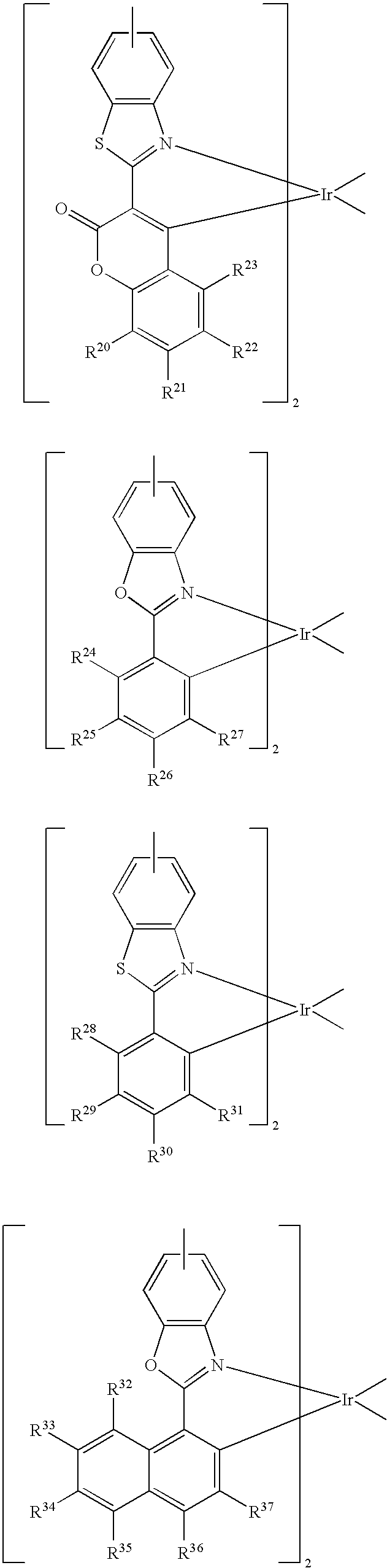
In a preferred example of this embodiment, the iridium complex containing (pentaphenyl)phenyl group comprises one selected from the group consisting of the following:
Figure US08461282-20130611-C00012
Figure US08461282-20130611-C00013
In a second embodiment of the present invention, a method for forming an iridium complex containing (pentaphenyl)phenyl group is provided. At first, a first reagent is provided, having the following general equation:
Figure US08461282-20130611-C00014

in which Z is a group VA element, X1 and X2 are independently selected from the group consisting of the following: chlorine (Cl), bromine (Br), and iodine (I), and X1 is different from X2. Next, a second reagent is provided, having the following general equation:
Figure US08461282-20130611-C00015

in which R is a hydrogen atom, alkyl group or aryl group, R1, R2, R3, and R4 can be the same or different, and R1, R2, R3, and R4 are independently selected from the group consisting of the following: hydrogen atom and electron-withdrawing group. Then, a Suzuki coupling reaction between the first reagent and the second reagent is carried out to form a first intermediate with the following structure:
Figure US08461282-20130611-C00016
A Sonogashira coupling reaction between phenylacetylene and the first intermediate is carried out to form a second intermediate having the following general equation:
Figure US08461282-20130611-C00017
After Sonogashira coupling reaction is complete, a Diels-Alder reaction between tetraphenylcyclopentadienone (TPCDO) and the second intermediate is carried out to form a third intermediate having the following general equation:
Figure US08461282-20130611-C00018
An addition reaction between iridium chloride and the third intermediate is carried out to form a halogen-bridged dimer iridium complex having the following general equation:
Figure US08461282-20130611-C00019

in which X3 is selected from the group consisting of the following: chlorine (Cl), bromine (Br), and iodine (I). Finally, a substitution reaction between a chelating agent and the halogen-bridged dimer iridium complex is carried out to form the iridium complex containing a (pentaphenyl)phenyl ligand. The iridium complex containing a (pentaphenyl)phenyl ligand has the following general equation:
Figure US08461282-20130611-C00020
Example 1
Referring to scheme 1,5-bromo-2-iodo-pyridine as a starting substance with selective reactivity reacts with Pd(PPh3)4 organic metallic catalyst. At first, the Suzuki coupling reaction between the starting substance and boric acid with different electron-withdrawing group is carried out. Then, the Sonogashira coupling reaction with phenylacetylene is carried out to substitute the bromine atom at the fifth position of the starting substance. Thus, this method can successfully obtain compounds 4˜6 and have ideal yield.
Figure US08461282-20130611-C00021
Referring to scheme 2, the Diels-Alder reaction between the compounds 4˜6 and tetraphenylcyclopentadienone (TPCDO) is carried out. The reaction requires high temperature, about 260° C., and TPCDO is the reaction medium. Thus, no solvent is added. The reaction takes place about 3 hrs to obtain compounds 7˜9 containing a (pentaphenyl)phenyl substituent.
Figure US08461282-20130611-C00022
Referring to scheme 3, in the synthesis of the iridium complex, the method reported by Nonoyama is used to synthesize a chlorine-bridged dimer iridium complex. 2-ethoxyethanol and deionized water with a ratio of 3:1 are used as the solvent. IrCl3.3H2O reacts with 2˜2.5 equivalent of ligand. After filtered, powders of chlorine-bridged dimer iridium complexes 10˜12 with pale yellow to yellow green color are obtained.
Figure US08461282-20130611-C00023
If the core of the complex, that is iridium, is tightly wrapped, the ligand can have intramolecular energy transfer and also prevent bare iridium from stacking with each other or forming excimer, that affects color purity. Therefore, the modification of the third ligand is proceeded. Referring to scheme 4, by using 2-ethoxyethanol as the solvent and sodium carbonate as the base, the reaction with various auxiliary ligands at 130° C. is carried out. After purified, the target iridium complexes 13˜17 are obtained. The HOMO, energy level difference Eg, and LUMO of the complexes 13˜17 are shown in Table 1.
TABLE 1
Figure US08461282-20130611-C00024
E1/2 OX HOMO λ Eg LUMO
Complexes (V) (V) (nm)c (V) (V)
13 Ir(ppy-6ph)2(acac) 0.861a 5.116 486.5 2.550 2.566
14 Ir(F-ppy-6ph)2(acac) 1.165a 5.420 458.0 2.709 2.711
15 Ir(F-ppy-6ph)2(pic) 1.378a 5.633 441.5 2.811 2.822
16 Ir(CF3-ppy-6ph)2(acac) 1.435a 5.690 425.0 2.920 2.770
17 Ir(CF3-ppy-6ph)2(pic) 1.613b 5.903 413.5 3.001 2.902
areversible redox potential relative to Cp2Fe/Cp2Fe+, detected in methylenechloride, where E1/2, Ferrocene OX = 0.545 V
breversible redox potential relative to Cp2Fe/Cp2Fe+, detected in acetonitrile, where E1/2, Ferrocene OX = 0.510 V
cpoint of intersection between the edge of the maximum absorption wavelength in the UV-Vis spectrum and the horizontal line
The spectra data of the compound 13 is as follows:
1H NMR (400 MHz, CDCl3): δ 7.92 (d, J=2.0 Hz, 2H), δ 7.29 (d, J=8.8 Hz, 2H), δ 7.16 (dd, J=2.0, 8.4 Hz, 2H), δ 6.98˜6.70 (m, 52H), δ 6.66˜6.64 (m, 2H), δ 6.61˜6.59 (m, 2H), δ 5.69 (d, J=6.8 Hz, 2H), δ 4.95 (s, 1H), δ 1.70 (s, 6H); 13C NMR (100 MHz, CDCl3): δ182.12, 164.79, 148.88, 147.16, 143.88, 140.74, 140.48, 140.28, 140.14, 139.99, 139.79, 139.73, 139.65, 139.12, 139.09, 138.77, 134.96, 134.07, 132.84, 130.96, 130.85, 130.79, 130.73, 130.70, 130.63, 130.60, 128.17, 127.35, 127.17, 126.60, 126.44, 126.28, 126.23, 126.19, 125.75, 125.14, 124.94, 124.90, 122.90, 119.84, 116.05, 101.55, 29.34; MS m/z FAB (NBA) 1414.3 (14), 1513.6 (4); HRMS (M+) calcd for C99H71IrN2O2 1512.5144. found 1512.5082 (M+). Anal. calcd for C99H71IrN2O2: C, 78.60; H, 4.73; N, 1.85. found C, 78.74; H, 5.02; N, 1.98.
The spectra data of the compound 14 is as follows:
MS m/z FAB (NBA) 1585.8 (0.04), 1586.8 (0.02); HRMS (M+) calcd for C99H67F4IrN2O2 1584.4767. found 1584.4712 (M+). Anal. calcd for C99H67F4IrN2O2: C, 75.03; H, 4.26; N, 1.77. found C, 75.07; H, 4.84; N, 1.53.
The spectra data of the compound 15 is as follows:
1H NMR (400 MHz, CD2Cl2): δ 8.43 (d, J=8.0 Hz, 1H), δ 8.16 (d, J=1.6 Hz, 1H), δ 8.14˜8.09 (m, 1H), δ 7.73˜7.69 (m, 2H), δ 7.42˜7.39 (m, 1H), δ 7.32 (d, J=5.2 Hz, 1H), δ 7.28 (dd, J=1.6, 8.4 Hz, 1H), δ 7.22 (dd, J=1.6, 8.4 Hz, 1H), δ 7.17˜7.13 (m, 1H), δ 7.08 (t, J=7.6 Hz, 1H), δ 7.03˜6.99 (m, 1H), δ 6.97˜6.69 (m, 42H), δ 6.58 (d, J=2.0 Hz, 1H), δ 6.50 (d, J=7.2 Hz, 1H), δ 6.46 (d, J=7.6 Hz, 1H), δ 6.35˜6.18 (m, 5H), δ 4.98 (dd, J=2.0, 7.8 Hz, 1H), δ 4.91 (dd, J=2.0, 7.8 Hz, 1H); 13C NMR (100 MHz, CD2Cl2): δ 171.41, 161.50, 160.60, 160.53, 159.03, 152.72, 151.52, 150.31, 149.36, 149.21, 148.59, 141.50, 141.32, 140.85, 140.74, 140.65, 140.54, 140.38, 140.26, 140.23, 140.12, 140.05, 139.97, 139.86, 139.71, 139.51, 139.30, 139.25, 139.03, 138.11, 135.90, 135.65, 134.47, 134.37, 131.43, 131.35, 131.32, 131.24, 131.20, 131.09, 131.04, 130.99, 130.89, 130.75, 130.68, 130.62, 130.16, 128.45, 128.37, 127.78, 127.59, 127.04, 126.97, 126.90, 126.80, 126.62, 126.58, 126.48, 126.43, 126.39, 126.11, 125.44, 125.34, 125.17, 121.25, 121.05, 120.74, 120.56, 115.34, 115.19, 114.59, 97.97, 97.71, 97.36; MS m/z FAB (NBA) 1486.3 (100), 1608.9 (48); HRMS (M+) calcd for C100H64F4IrN3O2 1607.4563. found 1607.4633 (M+).
The spectra data of the compound 16 is as follows:
1H NMR (400 MHz, CDCl3): δ 7.74 (s, 2H), δ 7.62 (s, 2H), δ 7.40˜7.33 (m, 6H), δ 7.29 (s, 2H), δ 6.97˜6.60 (m, 50H), δ 4.68 (s, 1H), δ 1.60 (s, 6H); 13C NMR (100 MHz, CDCl3): δ 183.05, 162.66, 150.31, 150.25, 141.32, 141.26, 141.02, 140.68, 140.65, 139.96, 139.94, 139.91, 139.74, 139.45, 138.54, 136.41, 136.11, 134.03, 133.70, 132.02, 131.21, 131.05, 130.95, 130.90, 130.83, 130.76, 130.64, 130.52, 127.33, 127.01, 126.84, 126.52, 126.40, 126.36, 126.32, 126.14, 125.81, 125.66, 125.20, 125.14, 123.13, 123.15, 122.83, 121.70, 121.29, 116.73, 101.83, 29.46; MS m/z FAB (NBA) 1686.7 (100), 1786.1 (34); HRMS (M+) calcd for C103H67F12IrN2O2 1784.4640. found 1784.4620 (M+). Anal. calcd for C103H67F12IrN2O2: C, 69.31; H, 3.78; N, 1.57. found C, 69.05; H, 4.03; N, 1.55.
The spectra data of the compound 17 is as follows:
1H NMR (400 MHz, CDCl3): δ 8.36 (d, J=8.0 Hz, 1H), δ 8.13˜8.08 (m, 2H), δ 7.77 (s, 2H), δ 7.45˜7.40 (m, 3H), δ 7.35˜7.26 (m, 4H), δ 7.20 (dd, J=2.0, 8.6 Hz, 1H), δ 7.13 (s, 1H), δ 7.00˜6.92 (m, 5H), δ 6.88˜6.56 (m, 39H), δ 6.50˜6.46 (m, 2H), δ 6.36 (d, J=7.6 Hz, 1H), δ 6.19 (d, J=6 Hz, 1H), δ 6.00 (d, J=5.6 Hz, 2H); 13C NMR (100 MHz, CDCl3): δ 170.91, 162.96, 161.63, 151.61, 150.05, 149.81, 148.99, 147.66, 141.48, 141.34, 141.00, 140.75, 140.69, 140.36, 140.24, 140.06, 140.00, 139.82, 139.80, 139.71, 139.68, 139.48, 138.56, 138.43, 138.37, 138.21, 136.18, 135.71, 135.24, 133.38, 133.11, 131.64, 131.10, 131.02, 130.93, 130.84, 130.80, 130.71, 130.34, 130.17, 129.89, 128.80, 128.04, 127.62, 127.09, 126.55, 126.51, 126.46, 126.33, 126.24, 126.07, 125.28, 125.17, 125.10, 125.01, 122.88, 121.96, 117.83, 117.11; MS m/z FAB (NBA) 1686.2 (100), 1808.7 (44); HRMS (M+) calcd for C104H64F12IrN3O2 1807.4436. found 1807.4353 (M+).
Example 2
Generally, vacuum evaporation is utilized to fabricate the OLED devices. In the vacuum evaporation method, compounds are evaporated under vacuum and deposited on the ITO glass. However, the compounds have to sustain high temperature like 300˜400° C. without decomposition or transformation. If the compounds decompose during the evaporation process, the decomposed compounds will contaminate the device to jeopardize the performance of the device. In the present invention, although the device is made by spin coating without direct heating compounds, the external current applied on these compounds during operating or testing generates heat and transfers heat to these compounds. Therefore, the materials used in the OLED devices require thermal stability. If the thermal decomposition temperature (Td) of the material is too low, its application will be limited.
On the other hand, the glass transition temperature (Tg) of the material also affects the lifetime, efficiency, and chromatic aberration of the device. Thus, if the Tg of the material is too low, the external heat source will soften the material or cause molecules to crystallize so as to have the diffusion problem in the interface, during the fabricating or testing process. The thermal characteristics of the iridium complexes 13˜17 in the example 1 are shown in Table 2.
TABLE 2
Molecular
Compound weight Td Tg
13 1512.51 423 222
14 1584.48 399 221
15 1607.46 459
16 1784.46 411 219
17 1807.44 470 245
Example 3 Fabrication and characteristics of the OLED device where the iridium complexes 13˜17 are doped in PVK.
The compound 14 is only slightly dissolved in dichlorobenzene and has terrible film formation property by spin coating its dichlorobenzene solution. The efficiency of the compound 14 is low. Therefore, the device characteristics are discussed only for those made with the iridium complexes 13, 15, 16, and 17.
The iridium complexes 13 and 15-17 are doped in poly(vinylcarbazole) [PVK, average MW 90000] and PVK is the host material. PVK, one of the carbazole derivatives, has good hole transport capability. The electron from cathode can stay on the iridium complex to wait for recombination with hole so as to emit light.
The fabricating processes of the device are described in the following. (1) For the hole injection layer, poly(3,4-ethylenedioxythiophene)-poly(styrene)sulfonic acid (hereinafter referred to as “[PEDOT/PSS]”) is spin coated with a thickness of 50 nm. (2) For the light emitting layer, 100 mg of the host material, PVK, 40 mg of the electron transport material, 2-(4-biphenylyl-5-(4-tertbutylphenyl)-1,2,3-oxadiazole (PBD), and the iridium complexes 13 and 15-17 with different doping ratios are added in 8 ml of the chloroform solution and the solution is spin coated and baked on the hole injection layer. (3) For the cathode, traditionally the metal or metal alloy with low work function, such as active metals like Li, Mg, Ca, is used to have electrons from the cathode injected into the electron transport layer. The cathode is formed by thermal evaporation. In addition, an electron injection layer can be provided between the cathode and the electron transport layer to reduce the energy barrier between the cathode and the electron transport layer so as to lower the driving voltage. The common material for the electron injection layer is very thin metal halide or oxide, such as LiF, MgO, or Li2O. The complete OLED device has a structure of ITO/PEDOT/13, 15-17-PBD-PVK/Mg/Ag (hereinafter referred to as “device I, II, III, and IV”, respectively). The content of the doped iridium complexes 13 and 15-17 ranges about 15 wt %˜40 wt %. The result is shown in FIGS. 1˜3. The maximum brightness for the device I, II, III, and IV is 2380, 355, 824, and 871 cd/m2, respectively, and the maximum efficiency is 22.7, 4.37, 18.5, and 15 cd/A, respectively. Besides, the electroluminescent spectra for the device I, II, III, and IV are shown in FIG. 4. Referring to FIG. 5, there is no red shift for the device with an increased doping ratio. Thus, the core metal of the compounds 13 and 15-17 is wrapped tightly. Therefore, T-T annihilation due to the higher doping ratio in fabricating does not occur. Besides, the luminance intensity is generally proportioned to the content of iridium. According to the present invention, the brightness can be increased by the increase of the doping ratio of the iridium complex.
A third embodiment of the present invention discloses a compound with a 9-[(pentaphenyl)phenyl]carbazole structure, having the following general equation:
Figure US08461282-20130611-C00025

in which G1 and G2 can be the same or different and G1 and G2 are independently selected from the group consisting of the following: hydrogen atom, carboxyl group, hydroxyl group, amino group, double bond group or triple bond group, halogen atom,
Figure US08461282-20130611-C00026

—B(OR)2,
Figure US08461282-20130611-C00027

and —Ar-G3, where R is a hydrogen atom, alkyl group, or aryl group, Ar is an aryl group, G3 is a hydrogen atom, carboxyl group, hydroxyl group, amino group, double bond group or triple bond group. In addition, the compound with a 9-[(pentaphenyl)phenyl]carbazole structure provided by the invention can be applied in an organic solar cell device or as a hole injection material, hole transport material, emitting material or host material in an organic electroluminescence device and/or phosphorescence device.
The compound with a 9-[(pentaphenyl)phenyl]carbazole structure provided by this embodiment can be used to form a polymer derived from a 9-[(pentaphenyl)phenyl]carbazole structure by the reaction between the compound with a 9-[(pentaphenyl)phenyl]carbazole structure and at least one reactive monomer. The reactive monomer is selected from the group consisting of the following:
Figure US08461282-20130611-C00028

in which R1, R2, R3, R4, and R5 are independently selected from the group consisting of the following: alkyl group and aryl group, G4 is a halogen atom, —B(OR)2,
Figure US08461282-20130611-C00029

carboxyl group, hydroxyl group, amino group, double bond group or triple bond group, where R is a hydrogen atom, alkyl group, or aryl group. The polymer derived from a 9-[(pentaphenyl)phenyl]carbazole structure can be applied in an organic solar cell device or as a hole injection material, hole transport material, emitting material or host material in an organic electroluminescence device and/or phosphorescence device.
Example 4
This example provides seven polymers derived from a 9-[(pentaphenyl)phenyl]carbazole structure, as shown in the following P1-P7, and a comparison polymer P8. The synthesis of the polymers P1, P2, and P4-P8 utilizes Suzuki coupling reaction. At first, borate or boric acid compound monomer and brominated monomer are dissolved in THF (as the solvent), Pd(PPh3)4 is the catalyst, P(t-Bu)3 is the ligand, K3PO4 is also added, and reflux reaction is carried out for 40 hrs under the reaction temperature of 70° C. Next, triphenylammonium bromide as a terminal group is added and the reaction proceeds for one additional day and then stops. Finally, chloroform is used to extract the crude polymer product. Toluene is used as the elute and the chromatographic column is used to remove salts and heavy metal catalyst. The product is treated by vacuum concentration and then reprecipitated in methanol. Thus, the purified polymer is obtained. The molecular weights and distribution of the polymers P1-P8 are shown in Table 3. Their HOMO and LUMO energy levels are shown in Table 4.
TABLE 3
P1
Figure US08461282-20130611-C00030
P2
Figure US08461282-20130611-C00031
P3
Figure US08461282-20130611-C00032
P4
Figure US08461282-20130611-C00033
P5
Figure US08461282-20130611-C00034
P6
Figure US08461282-20130611-C00035
P7
Figure US08461282-20130611-C00036
P8
Figure US08461282-20130611-C00037
Mn Mw PDI
P1 4400 5500 1.25
P2 14200 21000 1.48
P3 24000 35500 1.48
P4 16100 21200 1.33
P5 12200 18000 1.5
P6 16100 21600 1.35
P7 15200 21100 1.39
P8 6900 9100 1.32
TABLE 4
Oxidation Energy level
potential (V) difference (eV) HOMO LUMO
P1 0.87 3.16 5.13 1.97
P2 1.08 3.08 5.34 2.26
P3 0.68 2.49 4.94 2.45
P4 0.85 3.2 5.11 1.91
P5 0.81 3.16 5.07 1.91
P6 1.08 3.09 5.34 2.25
P7 1.2 3.08 5.46 2.38
P8 0.8 3.2 5.06 1.86
The effect of the thermal stability to the performance of the device can be explained in the following two parts. The first part is about the stability of the fabricating process at the early stage. The film of the polymer material is formed by spin coating without the requirement of vacuum evaporation, like that for the small molecule material, but the electrode is formed by thermal evaporation of metal. Thus, although the film of the compound is not heated directly, the temperature is still high as the metal is deposited on the polymer film. Therefore, if the thermal decomposition temperature is too low, decomposition occurs during evaporation. The second part is about the stability of the fabricating process at the later stage. The external voltage is continuously applied on the device during operation to generate heat and besides the heat of the operating environment is absorbed by the polymer in the device. Thus, if the glass transition temperature (Tg) is low, the organic material softens and the efficiency of the device is thereby affected.
Before fabricating the device, thermogravimetry analysis (TGA) is used to measure the thermal decomposition temperature (Td) of the compound and differential scanning calorimetry (DSC) is used to measure the glass transition temperature (Tg) of the compound so as to realize the thermal property of the material. The glass transition temperatures (Tg) and the thermal decomposition temperatures (Td) of the polymers P1-P8 are shown in Table 5. The thermal decomposition temperatures (Td) are all higher than 400° C. They all have good thermal stability. The glass transition temperatures (Tg) are all between 100˜120° C. and the Tg's of P1-P7 are higher than that of P8, without (pentaphenyl)phenyl group on the backbone. It is suspected that the steric effect of (pentaphenyl)phenyl group is so large that the rotational degree of freedom is decreased and thus Tg is increased.
TABLE 5
Thermal decomposition Glass transition
temperature (Td) temperature (Tg)
P1 436° C. 118° C.
P2 415° C.  99° C.
P3 432° C. 112° C.
P4 430° C. 118° C.
P5 421° C. 113° C.
P6 415° C. 109° C.
P7 418° C.  91° C.
P8 440° C.  83° C.
Example 5
Scheme 5 shows the synthesis process flow of P3. Horner-Wadsworth-Emmons reaction (HWE reaction) is utilized to polymerize P3. Under alkaline condition, the compound 14 reacts with the compound 15 to form carbon-carbon double bond so as to polymerize P3. It is predicted that the polymer formed by HWE reaction has higher molecular weight than that formed by Suzuki coupling reaction.
Figure US08461282-20130611-C00038
Example 6
P6 is used to fabricate the OLED devices V and VI, having the structures of ITO/PEDOT:PSS/P6/LiF/Al and ITO/PEDOT:PSS/P6-PBD-Ir(ppy)3/LiF/Al where P6:PBD:Ir(ppy)3 in weight ratio is 100:40:8(THF). Referring to FIGS. 5˜11, the device V with pure P6 emits green light and has a maximum brightness of 910 cd/m2. The performance of the device is fairly good without mixing any electron or hole transport material. The device VI mixed with iridium phosphorescent material emits green light. After doped with the guest material Ir(ppy)3, the brightness reaches 2700 cd/m2 and the maximum luminance efficiency is 5.2 cd/A. The characteristics of the devices V and VI are shown in Table 6.
TABLE 6
Threshold Max. Max.
voltage Brightness efficiency
Device (V) (cd/m2) (cd/A)
V 5.5 910 1.15
VI 11 2650 5.2
This embodiment also discloses a method for forming 9-[(pentaphenyl)phenyl]carbazole. At first a carbazole compound and a dihalo compound are provided, each having the following general equation:
Figure US08461282-20130611-C00039

respectively,
in which X1 and X2 can be the same or different and X1 and X2 are independently selected from the group consisting of the following: chlorine (Cl), bromine (Br), and iodine (I). Then, a substitution reaction between the carbazole and the dihalo compound is carried out to form a first intermediate having the following structural equation:
Figure US08461282-20130611-C00040
Next, a Sonogashira coupling reaction between phenylacetylene and the first intermediate is carried out to form a second intermediate having the following general equation:
Figure US08461282-20130611-C00041
Finally, a Diels-Alder reaction between tetraphenylcyclopentadienone (TPCDO) and the second intermediate is carried out to form 9-[(pentaphenyl)phenyl]carbazole having the following general equation:
Figure US08461282-20130611-C00042
Example 7
As shown in scheme 6, at first the compound 1 is formed by salt catalyzed reaction. The Sonogashira coupling reaction between the compound 1 and phenylacetylene is carried out to form the compound 2. Then, a Diels-Alder reaction between tetraphenylcyclopentadienone (TPCDO) and the compound 2 is carried out to form the compound 3. Finally, the compound is dissolved in THF to have bromination reaction with NBS. The 3,6-di-bromo-9-[(pentaphenyl)phenyl]carbazole 4 is thus formed.
The spectra data of the compound 3 is as follows:
mp 329° C.-332° C.; 1H NMR (400 MHz, CDCl3) δ 6.85˜7.02 (m, 31H), 7.23 (t, 2H), 7.32 (t, 2H), 8.06 (t, 2H); 13C NMR (400 MHz, CDCl3) δ 109.60, 119.57, 120.12, 123.97, 125.28, 125.32, 125.43, 125.59, 125.67, 126.63, 126.80, 131.41, 131.53, 134.425, 140.35, 140.40, 140.43, 140.47, 140.49, 140.92.
The spectra data of the compound 4 is as follows:
mp >380° C.; 1H NMR (400 MHz, CDCl3) δ 6.82˜6.94 (m, 29H), 7.01 (d, 2H), 7.41 (d, 2H), 8.10 (s, 2H); 13C NMR (400 MHz, CDCl3) δ 111.34, 112.75, 123.04, 123.65, 125.34, 125.37, 125.45, 126.66, 126.7, 126.82, 129.18, 131.36, 131.5, 132.99, 133.49, 139.87, 140.25, 140.31, 140.36, 140.44, 140.47, 141.23.
Figure US08461282-20130611-C00043
Figure US08461282-20130611-C00044
Example 8
As shown in scheme 7, at first the compound 3 is dissolved in dichloroethane. After POCL3 is dissolved in THF, it is then added into the solution of the compound 3 at 0° C. The reaction is carried out at 90° C. for 50 hrs. The compound 14 is obtained, having the following spectra data:
mp >380° C.; 1H NMR (400 MHz, CDCl3) δ 6.85˜7.09 (m, 29H), 7.94 (d, 2H), 8.64 (d, 2H), 10.11 (s, 2H); 13C NMR (400 MHz, CDCl3) δ88.
Figure US08461282-20130611-C00045
Example 9
As shown in scheme 8, the compound 4 dissolved in THF at −78° C. reacts with n-butyl lithium reagent and then reacts with 2-isoproxy-4,4,5,5-tetrametyl-1,3,2-dioxaborolan to obtain diborate compound 7.
Figure US08461282-20130611-C00046
Example 10
As shown in scheme 9, a Suzuki coupling reaction between the compound 4 and 1-boronic acid 4-methoxy-benzene is carried out and then hydrolysis takes place to obtain dihydroxy compound.
Figure US08461282-20130611-C00047
Figure US08461282-20130611-C00048
Example 11
As shown in scheme 10, a Suzuki coupling reaction between the diborate compound 7 and 1-chloro-4-vinylbenzene is carried out to obtain the compound with double bond. Such compound having double bond can be utilized in the proceeding reaction without addition of any solvent. Therefore, it does not endanger the environment and produce air pollution. In addition, it has the advantages of mild reaction condition (normal temperature and normal pressure), fast reaction rate, high transformation rate, cost effective. Thus, the product provide by this embodiment does have high commercial value.
Figure US08461282-20130611-C00049
Obviously many modifications and variations are possible in light of the above teachings. It is therefore to be understood that within the scope of the appended claims the present invention can be practiced otherwise than as specifically described herein. Although specific embodiments have been illustrated and described herein, it is obvious to those skilled in the art that many modifications of the present invention may be made without departing from what is intended to be limited solely by the appended claims.

Claims (4)

What is claimed is:
1. A polymer derived from a 9-[(pentaphenyl)phenyl]carbazole structure, formed by a reaction between a compound with a 9-[(pentaphenyl)phenyl]carbazole structure according, and at least one reactive monomer, wherein said compound has the following general equation:
Figure US08461282-20130611-C00050
in which G1 and G2 can be the same or different and G1 and G2 are independently selected from the group consisting of the following: halogen atom,
Figure US08461282-20130611-C00051
—B(OR)2, and
Figure US08461282-20130611-C00052
and
wherein said reactive monomer is selected from the group consisting of the following:
Figure US08461282-20130611-C00053
in which R1, R2, R3, R4, and R5 are independently selected from the group consisting of the following: alkyl group and aryl group, G4 is a halogen atom, —B(OR)2,
Figure US08461282-20130611-C00054
wherein R is a hydrogen atom, alkyl group, or aryl group.
2. The polymer according to claim 1, wherein said polymer derived from a 9-[(pentaphenyl)phenyl]carbazole structure is utilized in an organic solar cell device.
3. The polymer according to claim 1, wherein said polymer is utilized in an organic electroluminescence device and/or phosphorescence device.
4. The polymer according to claim 3, wherein said polymer is used as a hole injection material, hole transport material, emitting material or host material in an organic electroluminescence device and/or phosphorescence device.
US12/629,648 2007-05-22 2009-12-02 (Pentaphenyl)phenyl group containing compound, polymeric derivative thereof and method for forming the same Expired - Fee Related US8461282B2 (en)

Priority Applications (1)

Application Number Priority Date Filing Date Title
US12/629,648 US8461282B2 (en) 2007-05-22 2009-12-02 (Pentaphenyl)phenyl group containing compound, polymeric derivative thereof and method for forming the same

Applications Claiming Priority (2)

Application Number Priority Date Filing Date Title
US11/751,634 US20080293945A1 (en) 2007-05-22 2007-05-22 (Pentaphenyl)phenyl Group Containing Compound, Polymeric Derivative Thereof And Method For Forming The Same
US12/629,648 US8461282B2 (en) 2007-05-22 2009-12-02 (Pentaphenyl)phenyl group containing compound, polymeric derivative thereof and method for forming the same

Related Parent Applications (1)

Application Number Title Priority Date Filing Date
US11/751,634 Division US20080293945A1 (en) 2007-05-22 2007-05-22 (Pentaphenyl)phenyl Group Containing Compound, Polymeric Derivative Thereof And Method For Forming The Same

Publications (2)

Publication Number Publication Date
US20100137461A1 US20100137461A1 (en) 2010-06-03
US8461282B2 true US8461282B2 (en) 2013-06-11

Family

ID=40073021

Family Applications (2)

Application Number Title Priority Date Filing Date
US11/751,634 Abandoned US20080293945A1 (en) 2007-05-22 2007-05-22 (Pentaphenyl)phenyl Group Containing Compound, Polymeric Derivative Thereof And Method For Forming The Same
US12/629,648 Expired - Fee Related US8461282B2 (en) 2007-05-22 2009-12-02 (Pentaphenyl)phenyl group containing compound, polymeric derivative thereof and method for forming the same

Family Applications Before (1)

Application Number Title Priority Date Filing Date
US11/751,634 Abandoned US20080293945A1 (en) 2007-05-22 2007-05-22 (Pentaphenyl)phenyl Group Containing Compound, Polymeric Derivative Thereof And Method For Forming The Same

Country Status (1)

Country Link
US (2) US20080293945A1 (en)

Families Citing this family (8)

* Cited by examiner, † Cited by third party
Publication number Priority date Publication date Assignee Title
JP5556063B2 (en) 2008-06-23 2014-07-23 住友化学株式会社 Composition and light-emitting device using the composition
GB2481227A (en) * 2010-06-16 2011-12-21 Cambridge Display Tech Ltd An organic electroluminescent device comprising a plasticiser
US9018660B2 (en) * 2013-03-25 2015-04-28 Universal Display Corporation Lighting devices
KR101618426B1 (en) * 2014-01-21 2016-05-04 주식회사 두산 Organic compounds and organic electro luminescence device comprising the same
KR101765199B1 (en) * 2014-12-15 2017-08-07 (주)위델소재 Iridium complex compounds and organic electroluminescent device using the same
KR102582956B1 (en) * 2015-12-30 2023-09-25 엘지디스플레이 주식회사 Phosphorescent compound and Organic light emitting diode and Organic light emitting diode display device using the same
WO2018077769A1 (en) * 2016-10-25 2018-05-03 Merck Patent Gmbh Metal complexes
KR101914385B1 (en) * 2017-08-18 2018-11-01 울산과학기술원 Silicon solar cell and manufacturing method for the same

Citations (3)

* Cited by examiner, † Cited by third party
Publication number Priority date Publication date Assignee Title
JP2004244400A (en) 2002-12-19 2004-09-02 Chemiprokasei Kaisha Ltd 4,4 "-di- (aryl) -3 ', 4', 5 ', 6'-tetraphenyl-p-terphenyl derivative, method for producing the same, host material comprising the same, and electroluminescent device using the same
WO2006077130A1 (en) 2005-01-21 2006-07-27 Sensient Imaging Technologies Gmbh Triarylamine derivatives with space-filling side groups and use thereof
KR100681474B1 (en) 2005-11-24 2007-02-09 이수화학 주식회사 Nucleated phenylbenzene type organic electroluminescent material having aminostyryl group

Patent Citations (3)

* Cited by examiner, † Cited by third party
Publication number Priority date Publication date Assignee Title
JP2004244400A (en) 2002-12-19 2004-09-02 Chemiprokasei Kaisha Ltd 4,4 "-di- (aryl) -3 ', 4', 5 ', 6'-tetraphenyl-p-terphenyl derivative, method for producing the same, host material comprising the same, and electroluminescent device using the same
WO2006077130A1 (en) 2005-01-21 2006-07-27 Sensient Imaging Technologies Gmbh Triarylamine derivatives with space-filling side groups and use thereof
KR100681474B1 (en) 2005-11-24 2007-02-09 이수화학 주식회사 Nucleated phenylbenzene type organic electroluminescent material having aminostyryl group

Non-Patent Citations (3)

* Cited by examiner, † Cited by third party
Title
Boutagy et. al. "Olefin Synthesis with Organic Phosphonate Carbanions" Chemical Reviews, 1974, vol. 74, No. 1 87-99. *
Suzuki, A. "Chapter III.2.2 Overview of the Suzuki Protocol with B" in Handbook of Organopalladium Chemistry for Organic Synthesis, Negishi, E. ed. 2002 John Wiley & Sons, 249-262. *
Watanabe et al. "Hexaphenylbenzene Derivatives for Blue Organic Light-emitting Devices" Chemistry Letters, Mar. 29, 2007, 36, 590-591.

Also Published As

Publication number Publication date
US20100137461A1 (en) 2010-06-03
US20080293945A1 (en) 2008-11-27

Similar Documents

Publication Publication Date Title
US11788001B2 (en) Organic light emitting polymer comprising light-emitting repeat unit in backbone of polymer and device therewith
US9985210B2 (en) Organic electronic material, ink composition, and organic electronic element
US8461282B2 (en) (Pentaphenyl)phenyl group containing compound, polymeric derivative thereof and method for forming the same
Ren et al. Pendant homopolymer and copolymers as solution-processable thermally activated delayed fluorescence materials for organic light-emitting diodes
US9559307B2 (en) Polymer and organic electronic device
US9812644B2 (en) Composition containing dopant and co-polymers having non-conjugated spacer units and its use in OLED devices
TWI421273B (en) Polymer, organic optoelectronic device and display including the same
US9865822B2 (en) Blue phosphorescence compound and organic light emitting diode using the same
JP2004515506A (en) Deuterated organic semiconductor compounds for optoelectronic devices
US20200259085A1 (en) Treatment liquid containing ionic compound, organic electronic element, and method for producing organic electronic element
TW201626614A (en) Organic electroluminescent device and method of manufacturing same
KR101499283B1 (en) Electroluminescent materials and optical device
CN110268541A (en) Charge-transporting varnish
Su et al. Polyfluorene containing diphenylquinoline pendants and their applications in organic light emitting diodes
Yao et al. Triphenylamine-carbazole alternating copolymers bearing thermally activated delayed fluorescent emitting and host pendant groups for solution-processable OLEDs
US9735370B2 (en) Compound, device and method of making same
Lee et al. New host homopolymers containing pendant triphenylamine derivatives: Synthesis, optical, electrochemical properties and its blend with Ir (ppy) 3 for green phosphorescent organic light‐emitting devices
US7951965B2 (en) Phenanthrene derivatives and organic light-emitting diodes containing said phenanthrene derivative
US12082499B2 (en) Compound and its application
Lai et al. The ‘double dendron’approach to host free phosphorescent poly (dendrimer) OLEDs
US20150001509A1 (en) Composition
US20170365805A1 (en) Organic light-emitting device
TWI358412B (en)
JP2024125197A (en) Metal complex compound and method for producing same
Liao et al. Synthesis, characterization, and application of light‐emitting copolyfluorenes slightly doped with distyrylbenzene derivatives

Legal Events

Date Code Title Description
AS Assignment

Owner name: NATIONAL TAIWAN UNIVERSITY,TAIWAN

Free format text: ASSIGNMENT OF ASSIGNORS INTEREST;ASSIGNORS:HSIEH, KUO-HUANG;LEUNG, MAN-KIT;CHEN, WEN-CHANG;AND OTHERS;SIGNING DATES FROM 20070507 TO 20070519;REEL/FRAME:023595/0745

Owner name: NATIONAL TAIWAN UNIVERSITY, TAIWAN

Free format text: ASSIGNMENT OF ASSIGNORS INTEREST;ASSIGNORS:HSIEH, KUO-HUANG;LEUNG, MAN-KIT;CHEN, WEN-CHANG;AND OTHERS;SIGNING DATES FROM 20070507 TO 20070519;REEL/FRAME:023595/0745

FEPP Fee payment procedure

Free format text: PAYOR NUMBER ASSIGNED (ORIGINAL EVENT CODE: ASPN); ENTITY STATUS OF PATENT OWNER: SMALL ENTITY

REMI Maintenance fee reminder mailed
LAPS Lapse for failure to pay maintenance fees
STCH Information on status: patent discontinuation

Free format text: PATENT EXPIRED DUE TO NONPAYMENT OF MAINTENANCE FEES UNDER 37 CFR 1.362

FP Lapsed due to failure to pay maintenance fee

Effective date: 20170611