US8428683B2 - Wearable monitoring apparatus and driving method thereof - Google Patents
Wearable monitoring apparatus and driving method thereof Download PDFInfo
- Publication number
- US8428683B2 US8428683B2 US12/702,038 US70203810A US8428683B2 US 8428683 B2 US8428683 B2 US 8428683B2 US 70203810 A US70203810 A US 70203810A US 8428683 B2 US8428683 B2 US 8428683B2
- Authority
- US
- United States
- Prior art keywords
- sensor unit
- signal
- control unit
- sensor
- response signal
- Prior art date
- Legal status (The legal status is an assumption and is not a legal conclusion. Google has not performed a legal analysis and makes no representation as to the accuracy of the status listed.)
- Active, expires
Links
Images


Classifications
-
- A—HUMAN NECESSITIES
- A61—MEDICAL OR VETERINARY SCIENCE; HYGIENE
- A61B—DIAGNOSIS; SURGERY; IDENTIFICATION
- A61B5/00—Measuring for diagnostic purposes; Identification of persons
- A61B5/0002—Remote monitoring of patients using telemetry, e.g. transmission of vital signals via a communication network
- A61B5/0015—Remote monitoring of patients using telemetry, e.g. transmission of vital signals via a communication network characterised by features of the telemetry system
- A61B5/0024—Remote monitoring of patients using telemetry, e.g. transmission of vital signals via a communication network characterised by features of the telemetry system for multiple sensor units attached to the patient, e.g. using a body or personal area network
-
- A—HUMAN NECESSITIES
- A61—MEDICAL OR VETERINARY SCIENCE; HYGIENE
- A61B—DIAGNOSIS; SURGERY; IDENTIFICATION
- A61B5/00—Measuring for diagnostic purposes; Identification of persons
- A61B5/0002—Remote monitoring of patients using telemetry, e.g. transmission of vital signals via a communication network
- A61B5/0004—Remote monitoring of patients using telemetry, e.g. transmission of vital signals via a communication network characterised by the type of physiological signal transmitted
- A61B5/0006—ECG or EEG signals
-
- A—HUMAN NECESSITIES
- A61—MEDICAL OR VETERINARY SCIENCE; HYGIENE
- A61B—DIAGNOSIS; SURGERY; IDENTIFICATION
- A61B5/00—Measuring for diagnostic purposes; Identification of persons
- A61B5/145—Measuring characteristics of blood in vivo, e.g. gas concentration or pH-value ; Measuring characteristics of body fluids or tissues, e.g. interstitial fluid or cerebral tissue
- A61B5/14532—Measuring characteristics of blood in vivo, e.g. gas concentration or pH-value ; Measuring characteristics of body fluids or tissues, e.g. interstitial fluid or cerebral tissue for measuring glucose, e.g. by tissue impedance measurement
-
- A—HUMAN NECESSITIES
- A61—MEDICAL OR VETERINARY SCIENCE; HYGIENE
- A61B—DIAGNOSIS; SURGERY; IDENTIFICATION
- A61B5/00—Measuring for diagnostic purposes; Identification of persons
- A61B5/24—Detecting, measuring or recording bioelectric or biomagnetic signals of the body or parts thereof
- A61B5/25—Bioelectric electrodes therefor
- A61B5/251—Means for maintaining electrode contact with the body
- A61B5/257—Means for maintaining electrode contact with the body using adhesive means, e.g. adhesive pads or tapes
-
- A—HUMAN NECESSITIES
- A61—MEDICAL OR VETERINARY SCIENCE; HYGIENE
- A61B—DIAGNOSIS; SURGERY; IDENTIFICATION
- A61B5/00—Measuring for diagnostic purposes; Identification of persons
- A61B5/24—Detecting, measuring or recording bioelectric or biomagnetic signals of the body or parts thereof
- A61B5/25—Bioelectric electrodes therefor
- A61B5/263—Bioelectric electrodes therefor characterised by the electrode materials
-
- A—HUMAN NECESSITIES
- A61—MEDICAL OR VETERINARY SCIENCE; HYGIENE
- A61B—DIAGNOSIS; SURGERY; IDENTIFICATION
- A61B5/00—Measuring for diagnostic purposes; Identification of persons
- A61B5/24—Detecting, measuring or recording bioelectric or biomagnetic signals of the body or parts thereof
- A61B5/25—Bioelectric electrodes therefor
- A61B5/279—Bioelectric electrodes therefor specially adapted for particular uses
- A61B5/28—Bioelectric electrodes therefor specially adapted for particular uses for electrocardiography [ECG]
- A61B5/282—Holders for multiple electrodes
-
- A—HUMAN NECESSITIES
- A61—MEDICAL OR VETERINARY SCIENCE; HYGIENE
- A61B—DIAGNOSIS; SURGERY; IDENTIFICATION
- A61B5/00—Measuring for diagnostic purposes; Identification of persons
- A61B5/68—Arrangements of detecting, measuring or recording means, e.g. sensors, in relation to patient
- A61B5/6801—Arrangements of detecting, measuring or recording means, e.g. sensors, in relation to patient specially adapted to be attached to or worn on the body surface
- A61B5/6802—Sensor mounted on worn items
-
- A—HUMAN NECESSITIES
- A61—MEDICAL OR VETERINARY SCIENCE; HYGIENE
- A61B—DIAGNOSIS; SURGERY; IDENTIFICATION
- A61B5/00—Measuring for diagnostic purposes; Identification of persons
- A61B5/68—Arrangements of detecting, measuring or recording means, e.g. sensors, in relation to patient
- A61B5/6801—Arrangements of detecting, measuring or recording means, e.g. sensors, in relation to patient specially adapted to be attached to or worn on the body surface
- A61B5/683—Means for maintaining contact with the body
- A61B5/6831—Straps, bands or harnesses
-
- A—HUMAN NECESSITIES
- A61—MEDICAL OR VETERINARY SCIENCE; HYGIENE
- A61B—DIAGNOSIS; SURGERY; IDENTIFICATION
- A61B5/00—Measuring for diagnostic purposes; Identification of persons
- A61B5/72—Signal processing specially adapted for physiological signals or for diagnostic purposes
- A61B5/7225—Details of analogue processing, e.g. isolation amplifier, gain or sensitivity adjustment, filtering, baseline or drift compensation
-
- A—HUMAN NECESSITIES
- A61—MEDICAL OR VETERINARY SCIENCE; HYGIENE
- A61B—DIAGNOSIS; SURGERY; IDENTIFICATION
- A61B5/00—Measuring for diagnostic purposes; Identification of persons
- A61B5/72—Signal processing specially adapted for physiological signals or for diagnostic purposes
- A61B5/7232—Signal processing specially adapted for physiological signals or for diagnostic purposes involving compression of the physiological signal, e.g. to extend the signal recording period
-
- A—HUMAN NECESSITIES
- A61—MEDICAL OR VETERINARY SCIENCE; HYGIENE
- A61B—DIAGNOSIS; SURGERY; IDENTIFICATION
- A61B2562/00—Details of sensors; Constructional details of sensor housings or probes; Accessories for sensors
- A61B2562/02—Details of sensors specially adapted for in-vivo measurements
- A61B2562/0209—Special features of electrodes classified in A61B5/24, A61B5/25, A61B5/283, A61B5/291, A61B5/296, A61B5/053
Definitions
- the present invention relates to a wearable monitoring apparatus and a driving method thereof.
- a cardiovascular disease is a representative example of the chronic disease.
- a patient's electrocardiogram ECG
- ECG electrocardiogram
- a patient should carry a tester in state that an electrode with a plurality of lines is adhered to a body.
- a conventional monitoring apparatus has various problems. For example, because the patient should carry a wire of plural strands all day, he or she feels a globus syndrome that results in discomfort.
- a wet electrode is adhered in most cases, as time goes by, a skin disease can occur in a patient due to stimulation of the skin.
- a health management system known as “Toumaz Technology” is one such example of the technology.
- the health management system includes a wireless adhesive plaster type ECG patch and a monitoring data collecting unit for collecting data in a terminal such as a portable phone.
- a main disadvantage of the health management system is that the wireless adhesive plaster type ECG patch needs a separate power supply (battery or the like). In this case, since a patient must continue to live and carry on his daily routine with the battery adhered to the skin, when the patient sweats during a continuous monitoring procedure, a chemical reaction occurs which may potentially cause a safety problem.
- the wireless adhesive plaster type ECG patch and the monitoring data collecting unit communicate with each other based on a wireless communication using a radio frequency.
- a wireless communication can induce physiological interference and infringement danger.
- security and reliance are of utmost importance in characteristics of a device having to monitor a biological signal, a conventional approach using wireless communication is significantly dangerous.
- the present invention has been made in view of the above problems, and it is an object of the present invention to provide a wearable monitoring apparatus that may efficiently and safely monitor a biological signal without the wearers having to suffer from globus syndrome during their daily lives.
- a wearable monitoring apparatus for continuously monitoring a biological signal comprising: a sensor unit for measuring a biological signal from a human body, wherein the sensor unit is adhered to a skin; and a control unit for searching a location of the sensor unit, supplying power to the sensor unit, and receiving and processing the biological signal from the sensor unit, wherein the control unit is formed to be wearable.
- the sensor unit may comprise: an adhesive layer having adhesion and flexibility; an inductor for connecting to the control unit by wireless means using near field coupling; a sensing electrode for sensing the biological signal; a sensor chip for transmitting a response signal containing type information of the sensor unit to the control unit in response to a searching signal from the control unit, measuring the biological signal using the sensing electrode, and transmitting the measured biological signal to the control unit; and a molding portion formed to cover the sensor chip to prevent the sensor chip from being damaged from an outside, wherein at least one of the inductor and the sensing electrode is formed by printing a conductive material on a fiber.
- control unit may comprise: a plurality of inductors for connecting to the sensor unit by wireless means using near field coupling, wherein the plurality of inductors are arrayed in a coordinate matrix pattern; a power supply for providing the searching signal and power to be transmitted to the sensor unit; and a network controller for transmitting the searching signal in a set coordinate order using the plurality of inductors, receiving the response signal, storing the type information of the sensor unit and coordinate information of an inductor having received the response signal, supplying power to the sensor unit to meet set sensing cycle and power transmission strength according to a type of the sensor unit using the inductor having received the response signal, receiving the biological signal measured by the sensor unit, and storing the received biological signal, wherein the network controller is connected to the plurality of inductors, wherein the plurality of inductors are formed by printing a conductive material on a fiber.
- the sensory unit comprise: an adhesive layer having adhesion and flexibility; a first connector for connecting to the control unit by wired means, wherein a first connector is attached and detached to the control unit; a sensing electrode for sensing the biological signal; a sensor chip for transmitting a response signal containing type information of the sensor unit to the control unit in response to a searching signal from the control unit, measuring the biological signal using the sensing electrode, and transmitting the measured biological signal to the control unit; and a molding portion formed to cover the sensor chip to prevent the sensor chip from being damaged from an outside, wherein the sensing electrode is formed by printing a conductive material on a fiber.
- control unit can comprise: a plurality of second connectors for connecting to the sensor unit by wired means using the first connector, wherein the plurality of second connectors are arrayed in a coordinate matrix pattern, attached and detached to the sensor unit; a power supply for providing the searching signal and power to be transmitted to the sensor unit; and a network controller for transmitting the searching signal in a set coordinate order using the plurality of second connectors, receiving the response signal, storing the type information of the sensor unit and coordinate information of a second connector having received the response signal, transferring power to the sensor unit to meet a set sensing cycle and power transmission strength according to a type of the sensor unit using the second connector having received the response signal, receiving the biological signal measured by the sensor unit, and storing the received biological signal, wherein the network controller is connected to the plurality of second connectors.
- the first connector and the second connector can be configured in a form of a Velcro, a button, zipper, or a conductive contact, and can be made of a conductive material.
- a sensor unit of a wearable monitoring apparatus adhered to a human body and measuring a biological signal comprising: an adhesive layer having adhesion and flexibility; an inductor for connecting to a control unit by wireless means using near field coupling, the control unit collecting the biological signal measured by the sensor unit; a sensing electrode for sensing the biological signal; a sensor chip for transmitting a response signal to the control unit in response to a searching signal from the control unit, receiving power from the control unit to measure the biological signal using the sensing electrode, and transmitting the measured biological signal; and a molding portion formed to cover the sensor chip to prevent the sensor chip from being damaged from an outside, wherein at least one of the inductor and the sensing electrode is formed by printing a conductive material on a fiber.
- a sensor unit of a wearable monitoring apparatus adhered to a human body and measuring a biological signal comprising: an adhesive layer having adhesion and flexibility; a connector for connecting to a control unit by wired means, the control unit collecting the biological signal measured by the sensor unit, wherein the connector is attached and detached to the control unit; a sensing electrode for sensing the biological signal; a sensor chip for transmitting a response signal containing type information of the sensor unit to the control unit in response to a searching signal from the control unit, measuring the biological signal using the sensing electrode, and transmitting the measured biological signal to the control unit; and a molding portion formed to cover the sensor chip to prevent the sensor chip from being damaged from an outside, wherein the sensing electrode is formed by printing a conductive material on a fiber.
- a control unit of a wearable monitoring apparatus collecting a biological signal measured by a sensor unit adhered to a human body comprising: a plurality of inductors for connecting to the sensor unit by wireless means using near field coupling, wherein the plurality of inductors are arrayed in a coordinate matrix pattern; a power supply for providing a searching signal and power to be transmitted to the sensor unit; and a network controller for transmitting the searching signal in a set coordinate order using the plurality of inductors, receiving a response signal containing type information of the sensor unit as a response to the searching signal, storing the type information of the sensor unit and coordinate information of an inductor having received the response signal, transferring power to the sensor unit to meet a set sensing cycle and power transmission strength according to a type of the sensor unit using the inductor having received the response signal, receiving the biological signal measured by the sensor unit, and storing the received biological signal, wherein the network controller is connected to the plurality of inductors
- a control unit of a wearable monitoring apparatus collecting a biological signal measured by a sensor unit adhered to a human body comprising: a plurality of connectors for connecting to the sensor unit by wired means, wherein the plurality of connectors are arrayed in a coordinate matrix pattern, attached and detached to the sensor unit measuring the biological signal; a power supply providing a searching signal and power to be transmitted to the sensor unit; and a network controller for transmitting the searching signal in a set coordinate order using the plurality of connectors, receiving a response signal containing type information of the sensor unit as a response to the searching signal, storing the type information of the sensor unit and coordinate information of a connector having received the response signal, supplying power to the sensor unit to meet a set sensing cycle and power transmission strength according to a type of the sensor unit through the connector having received the response signal, receiving the biological signal measured by the sensor unit, and storing the received biological signal, wherein the network controller is connected to the plurality of connectors.
- the method of driving the wearable monitoring apparatus may comprise the steps of: (i) automatically searching a location of the sensor unit; (ii) supplying power to the sensor unit and measuring a biological signal; and (iii) transmitting the biological signal measured by the sensor unit to the control unit.
- step (i) further comprise: transmitting a searching signal in a set coordinate order using a plurality of inductors arrayed on the control unit in a coordinate matrix pattern; checking whether a response signal containing type information of the sensor unit as a response to the searching signal; and storing the response signal and coordinate values of an inductor having received the response signal when the response signal is received, and
- step (ii) can further comprise: recognizing a type of the sensor unit using the response signal; supplying power with a set sensing cycle and power transmission strength to the sensor unit using an inductor having received the response signal according to the recognized type of the sensor unit; and measuring the biological signal using the sensor unit, wherein the sensor unit and the control unit transmit and receive data in a wireless connection manner using near field coupling to and from each other.
- step (i) may comprise transmitting the searching signal using an inductor on next coordinates after storage of the response signal and the coordinate values of an inductor having received the response signal is terminated, and checks whether the response signal is received.
- step (i) may comprise: transmitting a searching signal in a set coordinate order using a plurality of connectors arrayed on the control unit in a coordinate matrix pattern; checking whether a response signal containing type information of the sensor unit as a response to the searching signal; and storing the response signal and coordinate values of an connector having received the response signal when the response signal is received, and
- step (ii) can comprise: recognizing a type of the sensor unit using the response signal; supplying power with a set sensing cycle and power transmission strength to the sensor unit using a connector having received the response signal according to the recognized type of the sensor unit; and measuring the biological signal using the sensor unit, wherein the sensor unit and the control unit transmit and receive data in a wired connection manner using the connector to and from each other.
- step (i) may include transmitting the searching signal using a connector on next coordinates after storage of the response signal and the coordinate values of a connector having received the response signal is terminated, and checks whether the response signal is received.
- step (ii) can include supplying power with different sensing cycles to respective sensor units when there are at least two types of the sensor units.
- step (iii) can comprise: amplifying, filtering and converting into digital data the biological signal measured by the sensor, and transmitting the digital data to the control unit; and compressing, encrypting, and storing the digital biological signal transmitted to the control unit.
- a dry electrode is used so as not to stimulate the skin at the point of adhesion for an excess amount of time, convenience can be increased.
- a control unit since a control unit is manufactured in the form of an abdominal bandage or article of clothing, a sensor unit does not need a separate power supply. Accordingly, it is not necessary to install a battery in the vicinity of the skin. Consequently, upon adhering the sensor unit, a wearable monitoring apparatus can be stably used despite the potential for the sensor unit to come into contact with sweat or water.
- FIG. 1 is a view illustrating a configuration of a wearable monitoring apparatus in accordance with an embodiment of the present invention
- FIG. 2 is a view illustrating a configuration of a sensor unit of a wearable monitoring apparatus in accordance with a first embodiment of the present invention
- FIG. 3 is a view illustrating a configuration of a control unit of a wearable monitoring apparatus in accordance with a first embodiment of the present invention
- FIG. 4 is a view illustrating selecting and operating methods of a sensor unit of the wearable monitoring apparatus in accordance with a first embodiment of the present invention
- FIG. 5 is a view illustrating a sensor unit in accordance with a second embodiment of the present invention.
- FIG. 6 is a view illustrating a control unit in accordance with a second embodiment of the present invention.
- FIG. 7 is a view illustrating a configuration of a second connector included in the control unit of the second example shown in FIG. 6 ;
- FIG. 8 is a flow chart illustrating a driving method of a wearable monitoring apparatus in accordance with an embodiment of the present invention.
- FIG. 9 and FIG. 10 are views illustrating an automatic searching method of a control unit in accordance with an embodiment of the present invention.
- FIG. 1 is a view illustrating a configuration of a wearable monitoring apparatus in accordance with an embodiment of the present invention.
- the wearable monitoring apparatus in accordance with an embodiment of the present invention includes a sensor unit 100 and a control unit 200 .
- FIG. 2 is a view illustrating a configuration of a sensor unit 100 of a wearable monitoring apparatus in accordance with a first embodiment of the present invention.
- the sensor unit 100 is attached or detached to or from a skin, and is configured to measure a biological signal from a human body.
- the sensor unit 100 may be a sensor for measuring electrocardiogram (ECG), glycemic index (GI), blood pressure or pulse, and the sensor unit 100 measures a biological signal in the same manner as in a conventional sensor for measuring a biological signal.
- ECG electrocardiogram
- GI glycemic index
- blood pressure or pulse measures a biological signal in the same manner as in a conventional sensor for measuring a biological signal.
- the sensor unit 100 includes an adhesive layer 110 , an inductor (or antenna) 121 for data communication, a sensing electrode 131 , a sensor chip 140 , and a molding portion 150 .
- the adhesive layer 110 may be made in a form of an adhesive plaster with adhesion and flexibility.
- the inductor 121 is an antenna for wireless communication, and is configured to be connected to inductors of the control unit 200 by wireless means using near field coupling such as inductive coupling.
- the inductor 121 may be formed by printing a conductive material such as a silver paste to be wound in a snail form on a fiber 120 using screen printing or sputtering.
- the inductor 121 may be disposed on the adhesive layer 110 .
- the sensing electrode 131 may sense a biological signal from the human body.
- the sensing electrode 131 may be a conductive material such as a silver paste printed on the fiber 130 by screen printing or sputtering.
- the sensor chip 140 transmits a response signal containing information regarding a type of the sensor unit 100 to the control unit 200 in response to a searching signal from the control unit 200 .
- the searching signal is a signal having a predetermined power level transmitted by the control unit 200 in order to recognize a location and a type of the sensor unit 100 .
- the sensor chip 140 Upon reception of the searching signal, the sensor chip 140 transmits the response signal to the control unit 200 .
- the sensor chip 140 After transmitting the response signal to the control unit 200 , the sensor chip 140 receives power from the control unit 200 using the inductor 121 and measures a biological signal using the sensing electrode 131 .
- the sensor chip 140 may amplify, filter, and convert the measured biological signal into digital data, and transmit the digital data, or may transmit the measured biological signal in a raw data state.
- the molding portion 150 can be configured to cover only the sensor chip 140 so as to minimize a globus syndrome. Meanwhile, the molding portion 150 can be configured to cover all of the inductor 121 , the sensing electrode 131 , and the sensor chip 140 if necessary.
- a formation order of the inductor 121 , the sensing electrode 131 , and the sensor chip 140 in the sensor unit 100 may be changed, and one or plural layers can be formed therein.
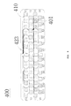
- FIG. 3 is a view illustrating a configuration of a control unit 200 of a wearable monitoring apparatus in accordance with a first embodiment of the present invention.
- the control unit 200 may include an abdominal bandage 210 , a plurality of 12 ⁇ 4 orthogonally arrayed inductors, a network controller 223 connected to the plurality of inductors, and a power supply (not shown) providing a searching signal to be transmitted and power to the sensor unit 100 .
- An article of clothing can be substituted for the abdominal bandage 210 .
- the control unit 200 periodically or non-periodically recognizes a location and a type of the sensor unit 100 using a type of near field coupling such as an inductive coupling communication system. Further, the control unit 200 supplies power with a set sensing cycle and a power transmission strength to the sensor unit 100 according to the recognized type of the sensor unit 100 . Moreover, the control unit 200 receives and processes the biological signal measured by the sensor unit 100 to allow a continuous health monitoring in everyday life.
- the plurality of inductors are arrayed on the abdominal bandage 210 in a coordinate matrix pattern (Xn, Yn). Furthermore, the plurality of inductors may be configured to be connected to the inductor 121 of the sensor unit 100 by wireless means using near field coupling such as inductive coupling. Although the plurality of inductors are orthogonally arrayed in the embodiment, the present invention is not limited thereto. For example, the plurality of inductors may be cross arranged or concentrated on a specific part of an article of clothing (underwear) or the abdominal bandage 210 . The plurality of inductors may be formed by printing a conductive material such as a silver paste to be wound in a snail form on the fiber 120 using screen printing or sputtering.
- a conductive material such as a silver paste to be wound in a snail form
- the network controller 223 automatically searches for the location and the type of the sensor unit 100 that is adhered to a predetermined part of a human body. To do this, the network controller 223 transmits a searching signal in a coordinate order determined by the plurality of inductors. Upon reception of the searching signal, the sensor unit 100 receives a response signal containing information about the type of the sensor unit 100 as a response to the searching signals. The searching signal can be sequentially transmitted in a set coordinate order using the plurality of inductors.
- the network controller 223 While the searching signal is being transmitted using an inductor among the plurality of inductors disposed on predetermined coordinates, if the network controller 223 does not receive a response signal from the sensor unit 100 for a predetermined time, the network controller 223 records completion of a valid time capable of transmitting the searching signal to an inductor on the coordinates, and moves its location to an inductor of next coordinates to transmit the searching signals. In this way, as shown in FIG. 4 , when the sensor unit 100 is present at a position corresponding to (X 3 , Y 1 ) coordinates during searching, the network controller 223 receives a response signal from the sensor unit 100 as a response to the searching signal 203 .
- the network controller 223 stores information relating to the type of the sensor unit 100 included in the response signal 205 and coordinate information (X 3 , Y 1 ) of an inductor 201 _ 31 having received the response signal 205 when the response signal 205 is received. Upon searching all positions, the network controller 223 terminates automatic sensor searching.
- the network controller 223 controls an operation of the sensor unit 100 based on the type information of the sensor unit 100 and coordinate information of an inductor having received the response signal 205 .
- the network controller 223 Prior to controlling the operation of the sensor unit 100 , the network controller 223 checks what type (for example, a sensor for measuring electrocardiogram (ECG), glycemic index (GI), blood pressure, or pulse) is the searched sensor unit 100 . In this case, since required operation cycles and power amounts differ according to sensors, the network controller 223 previously determines a set sensing cycle and power transmission strength according to a type of the sensor unit 100 , and then supplies power to meet them.
- ECG electrocardiogram
- GI glycemic index
- blood pressure or pulse
- the network controller 223 supplies power from the control unit 200 to the sensor unit 100 using an inductor 201 _ 31 on stored (X 3 , Y 1 ) coordinates and the inductor 121 of the sensor unit 100 .
- power is produced by inductive coupling to make a power source to be used in a circuit itself, the sensor unit 100 may perform an operation measuring a biological signal without a separate power source.
- the network controller 223 may amplify, filter, and convert the received biological signal into digital data, and store it using compression/encryption.
- the first embodiment of the present invention uses a wireless communication system
- the second embodiment of the present invention uses a wired communication system.
- a construction of the second embodiment of the present invention is similar to that of the first embodiment, except for a first connector 320 and a second connector 401 configured to directly connect the sensor unit 300 and the control unit 400 for wired communication.
- a construction of the second embodiment associated with differences from the first embodiment will be described.
- FIG. 5 is a view illustrating a sensor unit 300 in accordance with a second embodiment of the present invention.
- the sensor unit 300 includes an adhesive layer 310 , a first connector 320 , a sensing electrode 331 , a sensor chip 340 , and a molding portion 350 .
- the sensing electrode 331 may he a conductive material such as a silver paste printed on a fiber 330 by screen printing or sputtering.
- Constructions of the adhesive layer 310 , the sensing electrode 331 , the sensor chip 340 , and the molding portion 350 of the sensor unit 300 in accordance with a second embodiment of the present invention are identical with those of the adhesive layer 110 , the sensing electrode 131 , the sensor chip 140 , and the molding portion 150 of the sensor unit 100 in accordance with the first embodiment.
- the first connector 320 of the sensor unit 300 in accordance with a second embodiment of the present invention differs from the inductor 121 of the sensor unit 100 in accordance with the first embodiment, respectively.
- the first connector 320 can be attached and detached to and from the control unit 400 . Upon being attached, the first connector 320 is configured to be connected to the control unit 400 by wired means.
- FIG. 6 is a view illustrating a control unit 400 in accordance with a second embodiment of the present invention.
- the control unit 400 in accordance with a second embodiment of the present invention includes an abdominal bandage 410 , a plurality of second connectors 401 , a network controller 423 , and a power supply (not shown).
- the abdominal bandage 410 , the network controller 423 , and the power supply of the control unit 400 in accordance with a second embodiment of the present invention have the same constructions as those of the abdominal bandage 210 , the network controller 223 , and the power supply of the control unit 200 in accordance with the first embodiment.
- the second connector 401 of the control unit 400 in accordance with a second embodiment of the present invention differs from the inductor 201 of the control unit 200 in accordance with the first embodiment.
- the second connector 401 is disposed in a coordinate matrix pattern.
- the second connector 401 can be attached and detached to and from the sensor unit 300 . Upon being attached, the second connector 401 is configured to be connected to the sensor unit 300 by wired means.
- the sensor unit 300 and the control unit 400 can communicate with each other by a wired connection method due to a direct contact of the first connector 320 and the second connector 401 .
- the first connector 320 and the second connector 401 may be configured in a form of a Velcro, a zipper, a button, or a conductive contact to attach and detach the sensor unit 300 and the control unit 400 to and from each other. Further, the first connector 320 and the second connector 401 enable the sensor unit 300 and the control unit to exchange an electric signal with each other.
- the first connector 320 and the second connector 401 is configured in the form of a Velcro
- the first connector 320 is constructed to have a rough surface as shown in FIG. 5
- the second connector 401 is constructed to have a smooth surface as shown in FIG. 7 , thereby minimizing a globus syndrome upon wearing the control unit 400 .
- the first connector 320 and the second connector 401 are configured in the form of a button, they can be implemented by a snap fastener or a button using a magnet.
- the first connector 320 and the second connector 401 are configured in a form of a conductive contact, they can be implemented by a pair of plane magnets.
- the first connector 320 and the second connector 401 can be configured by a conductive contact of a clip or puzzle form.
- a driving method of a wearable monitoring apparatus in accordance with the present invention will be described with reference to the accompanying drawings.
- the first embodiment and the second embodiment are almost identical with each other except for using wired and wireless communication systems. Accordingly, a driving method of a wearable monitoring apparatus in accordance with a first embodiment will be described in detail as a representative example of a driving method of a wearable monitoring apparatus.
- FIG. 8 is a flow chart illustrating a driving method of a wearable monitoring apparatus in accordance with an embodiment of the present invention.
- a driving method of a wearable monitoring apparatus in accordance with a first embodiment of the present invention includes an apparatus wearing step (S 1 ), an automatic searching step (S 2 ), an automatic constructing step (S 3 ), and an information collecting step (S 4 ).
- a location of the sensor unit 100 is found, and a type of the sensor unit 100 is recognized.
- a searching signal is transmitted in a set coordinate order by a plurality of inductors disposed in the control unit 200 .
- the searching signal is transmitted using an inductor on first coordinates, it is checked whether the sensor unit 100 responds to the transmitted searching signal. If there are no responses after a predetermined time elapses, termination of a search valid time in a currently searched point is recorded and the searching signal is transmitted to an inductor of the next coordinates.
- the searching signal is transmitted to an inductor of the next coordinates.
- the automatic searching step (S 2 ) is terminated.
- FIG. 9 and FIG. 10 are views illustrating the automatic searching step (S 2 ) using the control unit 200 constructed by 12 ⁇ 4 inductor arrays.
- searching starts from an inductor on (X 0 , Y 0 ) coordinates
- the searching signal is transmitted to a current point.
- the coordinate value of Y 0 is increased from a current value by 1.
- it is checked whether a coordinate value of Y 1 is less than or equal to 3 and the foregoing procedures repeat.
- the automatic constructing step (S 3 ) recognizes a type and a location of the sensor unit 100 searched using the automatic sensor searching step (S 2 ).
- the location of the sensor unit 100 is a location corresponding to coordinate values of (X, Y) in which a response signal is received from the sensor unit 100 , the coordinate values are recorded so that the location can be recognized.
- the type of the sensor unit 100 can be recognized by using type information included in the received response signal.
- a set sensing cycle and power transmission strength are determined according to the recognized type of the sensor unit 100 , and power is supplied to the sensor unit according to the set values.
- the number of recognized types of the sensor unit 100 is equal to or greater than 2, power can be simultaneously or alternately supplied to respective sensor units.
- the sensor unit 100 may receive the power from the control unit 200 and produce a power source to measure a biological signal.
- a biological signal measured by the sensor chip 140 may be amplified, filtered, and converted into digital data, or be transmitted in a raw data state.
- the received biological signal can be amplified, filtered, and converted into digital data, and be stored using compression/encryption.
Landscapes
- Health & Medical Sciences (AREA)
- Life Sciences & Earth Sciences (AREA)
- Engineering & Computer Science (AREA)
- Physics & Mathematics (AREA)
- General Health & Medical Sciences (AREA)
- Animal Behavior & Ethology (AREA)
- Biomedical Technology (AREA)
- Heart & Thoracic Surgery (AREA)
- Medical Informatics (AREA)
- Molecular Biology (AREA)
- Surgery (AREA)
- Pathology (AREA)
- Biophysics (AREA)
- Public Health (AREA)
- Veterinary Medicine (AREA)
- Physiology (AREA)
- Computer Networks & Wireless Communication (AREA)
- Signal Processing (AREA)
- Psychiatry (AREA)
- Computer Vision & Pattern Recognition (AREA)
- Artificial Intelligence (AREA)
- Emergency Medicine (AREA)
- Optics & Photonics (AREA)
- Cardiology (AREA)
- Power Engineering (AREA)
- Measuring And Recording Apparatus For Diagnosis (AREA)
- Measurement And Recording Of Electrical Phenomena And Electrical Characteristics Of The Living Body (AREA)
Abstract
Description
Claims (20)
Applications Claiming Priority (2)
| Application Number | Priority Date | Filing Date | Title |
|---|---|---|---|
| KR1020090045173A KR101006824B1 (en) | 2009-05-22 | 2009-05-22 | Wearable monitoring device and its driving method |
| KR10-2009-0045173 | 2009-05-22 |
Publications (2)
| Publication Number | Publication Date |
|---|---|
| US20100298687A1 US20100298687A1 (en) | 2010-11-25 |
| US8428683B2 true US8428683B2 (en) | 2013-04-23 |
Family
ID=43125029
Family Applications (1)
| Application Number | Title | Priority Date | Filing Date |
|---|---|---|---|
| US12/702,038 Active 2031-07-03 US8428683B2 (en) | 2009-05-22 | 2010-02-08 | Wearable monitoring apparatus and driving method thereof |
Country Status (3)
| Country | Link |
|---|---|
| US (1) | US8428683B2 (en) |
| KR (1) | KR101006824B1 (en) |
| DE (1) | DE102010007347A1 (en) |
Cited By (4)
| Publication number | Priority date | Publication date | Assignee | Title |
|---|---|---|---|---|
| US20150065841A1 (en) * | 2013-08-30 | 2015-03-05 | Industry-Academic Cooperation Foundation, Yonsei University | Conductive textile-based inductance-type electrode apparatus for bio-signal detection |
| US9958483B2 (en) | 2015-04-02 | 2018-05-01 | Samsung Electronics Co., Ltd. | Methods of detecting change in object and apparatuses for performing the methods |
| US10624583B2 (en) | 2012-11-09 | 2020-04-21 | Nonin Medical, Inc. | Reactance sensing for improved sensor placement |
| US11883176B2 (en) | 2020-05-29 | 2024-01-30 | The Research Foundation For The State University Of New York | Low-power wearable smart ECG patch with on-board analytics |
Families Citing this family (23)
| Publication number | Priority date | Publication date | Assignee | Title |
|---|---|---|---|---|
| PT4122383T (en) | 2010-05-08 | 2025-05-02 | Univ California | Sem scanner sensing apparatus, system and methodology for early detection of ulcers |
| CN102551730A (en) * | 2011-12-15 | 2012-07-11 | 无锡市仁科医疗电子有限公司 | Device for simulating actions of abdominal wall surface and simulation method thereof |
| CN102715908A (en) * | 2012-07-06 | 2012-10-10 | 四川大学 | Monitor for physical energy under motion state |
| US9703751B2 (en) * | 2012-11-07 | 2017-07-11 | Nokia Technologies Oy | Apparatus and sensors for attachment to the apparatus |
| WO2014085350A1 (en) * | 2012-11-30 | 2014-06-05 | University Of Rochester | Implantable pressure monitor |
| US10952634B2 (en) * | 2013-10-04 | 2021-03-23 | Swisstom Ag | Electrical impedance tomography system |
| CN103908247B (en) * | 2014-04-08 | 2015-10-14 | 北京邮电大学 | A kind of Wearable electrocardiosignal real-time acquisition device |
| JP6580863B2 (en) | 2014-05-22 | 2019-09-25 | 株式会社半導体エネルギー研究所 | Semiconductor devices, health management systems |
| WO2016028056A1 (en) * | 2014-08-18 | 2016-02-25 | Samsung Electronics Co., Ltd. | Wearable biometric information measurement device |
| KR102335766B1 (en) * | 2014-10-08 | 2021-12-06 | 삼성전자주식회사 | Wearable device having an attachable and detachable sensor for detecting a biological signal and method of controlling wearable device |
| AU2016250527B2 (en) * | 2015-04-24 | 2021-01-14 | Bruin Biometrics, Llc | Apparatus and methods for determining damaged tissue using sub-epidermal moisture measurements |
| US10939847B2 (en) * | 2015-10-07 | 2021-03-09 | Verily Life Sciences Llc | Radio frequency and optical reader scanning array |
| EP3380006B1 (en) * | 2015-11-29 | 2022-04-27 | Ramot at Tel-Aviv University Ltd. | Sensing electrode and method of fabricating the same |
| BR102016025939B1 (en) * | 2016-11-07 | 2023-05-02 | Lótus Medicina Avançada | WEARABLE ELECTROCARDIOGRAPHIC MONITORING (ECG) TECHNOLOGY WITH HERMETIC RESERVOIR FOR MEDICINES AND INTEGRATED MEDICAL MONITORING SYSTEM |
| EP4241670B1 (en) | 2017-02-03 | 2025-12-10 | BBI Medical Innovations, LLC | Measurement of tissue viability |
| KR102304070B1 (en) | 2017-02-03 | 2021-09-23 | 브루인 바이오메트릭스, 엘엘씨 | measurement of edema |
| US20180220954A1 (en) | 2017-02-03 | 2018-08-09 | Bruin Biometrics, Llc | Measurement of susceptibility to diabetic foot ulcers |
| CN116473517A (en) | 2017-11-16 | 2023-07-25 | 布鲁恩生物有限责任公司 | Strategic Treatment of Pressure Ulcers Using Subepidermal Moisture Values |
| PL3749181T3 (en) | 2018-02-09 | 2024-06-10 | Bruin Biometrics, Llc | Detection of tissue damage |
| CA3094526C (en) * | 2018-03-23 | 2025-04-01 | The Alfred E. Mann Foundation For Scientific Research | Skin patches for sensing or affecting a body parameter |
| GB2591899B (en) | 2018-10-11 | 2022-03-09 | Bruin Biometrics Llc | Device with disposable element |
| KR20220108645A (en) | 2021-01-27 | 2022-08-03 | 주식회사 원바이오젠 | Body-attached patch for measuring metabolic syndrome with real-time monitoring |
| WO2022169850A1 (en) | 2021-02-03 | 2022-08-11 | Bruin Biometrics, Llc | Methods of treating deep and early-stage pressure induced tissue damage |
Citations (11)
| Publication number | Priority date | Publication date | Assignee | Title |
|---|---|---|---|---|
| US5465727A (en) | 1994-08-26 | 1995-11-14 | Brunswick Biomedical Corporation | Twelve-lead portable heart monitor |
| DE29620395U1 (en) | 1996-02-11 | 1997-03-06 | Bedrich, Michael R., Dipl.-Phys., 01445 Radebeul | Body electrode system |
| DE19607222A1 (en) | 1996-02-11 | 1997-08-14 | Michael R Dipl Phys Bedrich | Implantable chip for medical bio-potential storage and percutaneous read-out |
| US5882300A (en) * | 1996-11-07 | 1999-03-16 | Spacelabs Medical, Inc. | Wireless patient monitoring apparatus using inductive coupling |
| DE19749768A1 (en) | 1997-11-11 | 1999-05-12 | Fachhochschule Offenburg | Patch with data recording function for recording and storing electrocardiogram signals |
| US6240316B1 (en) * | 1998-08-14 | 2001-05-29 | Advanced Bionics Corporation | Implantable microstimulation system for treatment of sleep apnea |
| US6416471B1 (en) * | 1999-04-15 | 2002-07-09 | Nexan Limited | Portable remote patient telemonitoring system |
| US6496705B1 (en) * | 2000-04-18 | 2002-12-17 | Motorola Inc. | Programmable wireless electrode system for medical monitoring |
| US20030100821A1 (en) * | 2001-01-02 | 2003-05-29 | Therasense, Inc. | Analyte monitoring device and methods of use |
| US20040176805A1 (en) * | 2003-03-06 | 2004-09-09 | Whelan Andrew J. | Electromagnetic therapy device and methods |
| US20080312520A1 (en) * | 2007-06-15 | 2008-12-18 | Gordon Ian Rowlandson | Method and apparatus for acquiring physiological data |
Family Cites Families (3)
| Publication number | Priority date | Publication date | Assignee | Title |
|---|---|---|---|---|
| DE102004047650B3 (en) * | 2004-09-30 | 2006-04-13 | W.L. Gore & Associates Gmbh | Garment with inductive coupler and inductive garment interface |
| KR100759948B1 (en) | 2005-12-08 | 2007-09-19 | 한국전자통신연구원 | Garment apparatus for measuring physiological signal |
| KR100859320B1 (en) * | 2007-02-06 | 2008-09-19 | 한국과학기술원 | Non-contact communication device |
-
2009
- 2009-05-22 KR KR1020090045173A patent/KR101006824B1/en not_active Expired - Fee Related
-
2010
- 2010-02-08 US US12/702,038 patent/US8428683B2/en active Active
- 2010-02-09 DE DE102010007347A patent/DE102010007347A1/en not_active Withdrawn
Patent Citations (11)
| Publication number | Priority date | Publication date | Assignee | Title |
|---|---|---|---|---|
| US5465727A (en) | 1994-08-26 | 1995-11-14 | Brunswick Biomedical Corporation | Twelve-lead portable heart monitor |
| DE29620395U1 (en) | 1996-02-11 | 1997-03-06 | Bedrich, Michael R., Dipl.-Phys., 01445 Radebeul | Body electrode system |
| DE19607222A1 (en) | 1996-02-11 | 1997-08-14 | Michael R Dipl Phys Bedrich | Implantable chip for medical bio-potential storage and percutaneous read-out |
| US5882300A (en) * | 1996-11-07 | 1999-03-16 | Spacelabs Medical, Inc. | Wireless patient monitoring apparatus using inductive coupling |
| DE19749768A1 (en) | 1997-11-11 | 1999-05-12 | Fachhochschule Offenburg | Patch with data recording function for recording and storing electrocardiogram signals |
| US6240316B1 (en) * | 1998-08-14 | 2001-05-29 | Advanced Bionics Corporation | Implantable microstimulation system for treatment of sleep apnea |
| US6416471B1 (en) * | 1999-04-15 | 2002-07-09 | Nexan Limited | Portable remote patient telemonitoring system |
| US6496705B1 (en) * | 2000-04-18 | 2002-12-17 | Motorola Inc. | Programmable wireless electrode system for medical monitoring |
| US20030100821A1 (en) * | 2001-01-02 | 2003-05-29 | Therasense, Inc. | Analyte monitoring device and methods of use |
| US20040176805A1 (en) * | 2003-03-06 | 2004-09-09 | Whelan Andrew J. | Electromagnetic therapy device and methods |
| US20080312520A1 (en) * | 2007-06-15 | 2008-12-18 | Gordon Ian Rowlandson | Method and apparatus for acquiring physiological data |
Cited By (5)
| Publication number | Priority date | Publication date | Assignee | Title |
|---|---|---|---|---|
| US10624583B2 (en) | 2012-11-09 | 2020-04-21 | Nonin Medical, Inc. | Reactance sensing for improved sensor placement |
| US20150065841A1 (en) * | 2013-08-30 | 2015-03-05 | Industry-Academic Cooperation Foundation, Yonsei University | Conductive textile-based inductance-type electrode apparatus for bio-signal detection |
| US10172553B2 (en) * | 2013-08-30 | 2019-01-08 | Industry-Academic Cooperation Foundation, Yonsei University | Conductive textile-based inductance-type electrode apparatus for bio-signal detection |
| US9958483B2 (en) | 2015-04-02 | 2018-05-01 | Samsung Electronics Co., Ltd. | Methods of detecting change in object and apparatuses for performing the methods |
| US11883176B2 (en) | 2020-05-29 | 2024-01-30 | The Research Foundation For The State University Of New York | Low-power wearable smart ECG patch with on-board analytics |
Also Published As
| Publication number | Publication date |
|---|---|
| US20100298687A1 (en) | 2010-11-25 |
| KR101006824B1 (en) | 2011-01-10 |
| KR20100126107A (en) | 2010-12-01 |
| DE102010007347A1 (en) | 2011-07-07 |
Similar Documents
| Publication | Publication Date | Title |
|---|---|---|
| US8428683B2 (en) | Wearable monitoring apparatus and driving method thereof | |
| US11043302B2 (en) | Common display unit for a plurality of cableless medical sensors | |
| US12597514B2 (en) | Wearable sensor and system thereof | |
| CN105249612B (en) | A kind of multifunctional intellectual shoe-pad and intelligent shoe | |
| EP2241032B1 (en) | Capacitive sensing and communicating | |
| US9571907B2 (en) | Nth leadless electrode telemetry device, system and method of use | |
| JP2018149355A (en) | Apparatus and method for monitoring | |
| US20160331257A1 (en) | Electrical Patch for Physiological Measurements | |
| US20150335947A1 (en) | Sports device and system | |
| CN202270022U (en) | Wearable clothing that detects the human heart signal | |
| KR101092300B1 (en) | Wearable monitoring device | |
| KR102706318B1 (en) | patch type sensor module | |
| EP3687393B1 (en) | Device and system for providing physiological data monitoring of patients | |
| KR101203902B1 (en) | Bio-signal measurement unit of exercise prescription system | |
| CN213030630U (en) | Wearable acquisition equipment and wearable acquisition system | |
| US9402543B2 (en) | Nth leadless electrode telemetry device, system and method of use | |
| GB2585729A (en) | Electronics module for a wearable article | |
| US20250114041A1 (en) | Wearable sensor and system thereof | |
| GB2592900A (en) | Electronics module for a wearable article | |
| CA2896410A1 (en) | Smart wireless electrode array | |
| US20170007141A1 (en) | Smart wireless electrode array | |
| Lee | Sensing system and sensing method of passive patch interface for gathering bioinformation | |
| GB2585728A (en) | Electronics module for a wearable article | |
| GB2596932A (en) | Electronics module for a wearable article | |
| Tae-Gyu | Sensing system and sensing method of passive patch interface for gathering bioinformation |
Legal Events
| Date | Code | Title | Description |
|---|---|---|---|
| AS | Assignment |
Owner name: KOREA ADVANCED INSTITUTE OF SCIENCE AND TECHNOLOGY Free format text: ASSIGNMENT OF ASSIGNORS INTEREST;ASSIGNORS:YOO, HOI-JUN;YOO, JERALD;REEL/FRAME:024102/0109 Effective date: 20100204 |
|
| FEPP | Fee payment procedure |
Free format text: PAYOR NUMBER ASSIGNED (ORIGINAL EVENT CODE: ASPN); ENTITY STATUS OF PATENT OWNER: SMALL ENTITY |
|
| STCF | Information on status: patent grant |
Free format text: PATENTED CASE |
|
| FPAY | Fee payment |
Year of fee payment: 4 |
|
| FEPP | Fee payment procedure |
Free format text: 7.5 YR SURCHARGE - LATE PMT W/IN 6 MO, SMALL ENTITY (ORIGINAL EVENT CODE: M2555); ENTITY STATUS OF PATENT OWNER: SMALL ENTITY |
|
| MAFP | Maintenance fee payment |
Free format text: PAYMENT OF MAINTENANCE FEE, 8TH YR, SMALL ENTITY (ORIGINAL EVENT CODE: M2552); ENTITY STATUS OF PATENT OWNER: SMALL ENTITY Year of fee payment: 8 |
|
| FEPP | Fee payment procedure |
Free format text: MAINTENANCE FEE REMINDER MAILED (ORIGINAL EVENT CODE: REM.); ENTITY STATUS OF PATENT OWNER: SMALL ENTITY |
|
| FEPP | Fee payment procedure |
Free format text: 11.5 YR SURCHARGE- LATE PMT W/IN 6 MO, SMALL ENTITY (ORIGINAL EVENT CODE: M2556); ENTITY STATUS OF PATENT OWNER: SMALL ENTITY |
|
| MAFP | Maintenance fee payment |
Free format text: PAYMENT OF MAINTENANCE FEE, 12TH YR, SMALL ENTITY (ORIGINAL EVENT CODE: M2553); ENTITY STATUS OF PATENT OWNER: SMALL ENTITY Year of fee payment: 12 |