US8420256B2 - Controlling leakage in an electrochemical cell - Google Patents
Controlling leakage in an electrochemical cell Download PDFInfo
- Publication number
- US8420256B2 US8420256B2 US11/656,839 US65683907A US8420256B2 US 8420256 B2 US8420256 B2 US 8420256B2 US 65683907 A US65683907 A US 65683907A US 8420256 B2 US8420256 B2 US 8420256B2
- Authority
- US
- United States
- Prior art keywords
- flow
- opening
- flow plate
- fuel
- leakage
- Prior art date
- Legal status (The legal status is an assumption and is not a legal conclusion. Google has not performed a legal analysis and makes no representation as to the accuracy of the status listed.)
- Active, expires
Links
Images


Classifications
-
- H—ELECTRICITY
- H01—ELECTRIC ELEMENTS
- H01M—PROCESSES OR MEANS, e.g. BATTERIES, FOR THE DIRECT CONVERSION OF CHEMICAL ENERGY INTO ELECTRICAL ENERGY
- H01M8/00—Fuel cells; Manufacture thereof
- H01M8/02—Details
- H01M8/0271—Sealing or supporting means around electrodes, matrices or membranes
-
- C—CHEMISTRY; METALLURGY
- C25—ELECTROLYTIC OR ELECTROPHORETIC PROCESSES; APPARATUS THEREFOR
- C25B—ELECTROLYTIC OR ELECTROPHORETIC PROCESSES FOR THE PRODUCTION OF COMPOUNDS OR NON-METALS; APPARATUS THEREFOR
- C25B9/00—Cells or assemblies of cells; Constructional parts of cells; Assemblies of constructional parts, e.g. electrode-diaphragm assemblies; Process-related cell features
- C25B9/17—Cells comprising dimensionally-stable non-movable electrodes; Assemblies of constructional parts thereof
- C25B9/19—Cells comprising dimensionally-stable non-movable electrodes; Assemblies of constructional parts thereof with diaphragms
-
- H—ELECTRICITY
- H01—ELECTRIC ELEMENTS
- H01M—PROCESSES OR MEANS, e.g. BATTERIES, FOR THE DIRECT CONVERSION OF CHEMICAL ENERGY INTO ELECTRICAL ENERGY
- H01M8/00—Fuel cells; Manufacture thereof
- H01M8/04—Auxiliary arrangements, e.g. for control of pressure or for circulation of fluids
- H01M8/04082—Arrangements for control of reactant parameters, e.g. pressure or concentration
- H01M8/04089—Arrangements for control of reactant parameters, e.g. pressure or concentration of gaseous reactants
-
- H—ELECTRICITY
- H01—ELECTRIC ELEMENTS
- H01M—PROCESSES OR MEANS, e.g. BATTERIES, FOR THE DIRECT CONVERSION OF CHEMICAL ENERGY INTO ELECTRICAL ENERGY
- H01M8/00—Fuel cells; Manufacture thereof
- H01M8/24—Grouping of fuel cells, e.g. stacking of fuel cells
- H01M8/2465—Details of groupings of fuel cells
-
- H—ELECTRICITY
- H01—ELECTRIC ELEMENTS
- H01M—PROCESSES OR MEANS, e.g. BATTERIES, FOR THE DIRECT CONVERSION OF CHEMICAL ENERGY INTO ELECTRICAL ENERGY
- H01M8/00—Fuel cells; Manufacture thereof
- H01M8/10—Fuel cells with solid electrolytes
- H01M2008/1095—Fuel cells with polymeric electrolytes
-
- Y—GENERAL TAGGING OF NEW TECHNOLOGICAL DEVELOPMENTS; GENERAL TAGGING OF CROSS-SECTIONAL TECHNOLOGIES SPANNING OVER SEVERAL SECTIONS OF THE IPC; TECHNICAL SUBJECTS COVERED BY FORMER USPC CROSS-REFERENCE ART COLLECTIONS [XRACs] AND DIGESTS
- Y02—TECHNOLOGIES OR APPLICATIONS FOR MITIGATION OR ADAPTATION AGAINST CLIMATE CHANGE
- Y02E—REDUCTION OF GREENHOUSE GAS [GHG] EMISSIONS, RELATED TO ENERGY GENERATION, TRANSMISSION OR DISTRIBUTION
- Y02E60/00—Enabling technologies; Technologies with a potential or indirect contribution to GHG emissions mitigation
- Y02E60/30—Hydrogen technology
- Y02E60/50—Fuel cells
-
- Y—GENERAL TAGGING OF NEW TECHNOLOGICAL DEVELOPMENTS; GENERAL TAGGING OF CROSS-SECTIONAL TECHNOLOGIES SPANNING OVER SEVERAL SECTIONS OF THE IPC; TECHNICAL SUBJECTS COVERED BY FORMER USPC CROSS-REFERENCE ART COLLECTIONS [XRACs] AND DIGESTS
- Y10—TECHNICAL SUBJECTS COVERED BY FORMER USPC
- Y10T—TECHNICAL SUBJECTS COVERED BY FORMER US CLASSIFICATION
- Y10T29/00—Metal working
- Y10T29/49—Method of mechanical manufacture
- Y10T29/49002—Electrical device making
- Y10T29/49108—Electric battery cell making
- Y10T29/4911—Electric battery cell making including sealing
Definitions
- the invention generally relates to controlling leakage in an electrochemical cell, such as a hydrogen pump cell or a fuel cell, as examples.
- a fuel cell is an electrochemical device that converts chemical energy directly into electrical energy.
- one type of fuel cell includes a proton exchange membrane (PEM) that permits only protons to pass between an anode and a cathode of the fuel cell.
- PEM fuel cells employ sulfonic-acid-based ionomers, such as Nafion, and operate in the 50° Celsius (C) to 75° C. temperature range.
- Another type employs a phosphoric-acid-based polybenziamidazole, PBI, membrane that operates in the 150° to 200° temperature range.
- diatomic hydrogen a fuel
- the PEM fuel cell is only one type of fuel cell.
- Other types of fuel cells include direct methanol, alkaline, phosphoric acid, molten carbonate and solid oxide fuel cells.
- a typical fuel cell has a terminal voltage near one volt DC.
- several fuel cells may be assembled together to form an arrangement called a fuel cell stack, an arrangement in which the fuel cells are electrically coupled together in series to form a larger DC voltage (a voltage near 100 volts DC, for example) and to provide more power.
- the fuel cell stack may include flow plates (graphite composite or metal plates, as examples) that are stacked one on top of the other, and each plate may be associated with more than one cell of the stack.
- the plates may include various surface flow channels and orifices to, as examples, route the reactants and products through the fuel cell stack.
- Electrically conductive gas diffusion layers may be located on each side of a catalyzed PEM to form the anode and cathodes of each fuel cell. In this manner, reactant gases from both the anode and cathode flow-fields may diffuse through the GDLs to reach the catalyst layers.
- a fuel cell is an electrochemical cell that operates in a forward mode to produce power.
- the electrochemical cell may be operated in a reverse mode in which the cell produces hydrogen and oxygen from electricity and water.
- an electrolyzer splits water into hydrogen and oxygen with the following reactions occurring at the anode and cathode, respectively: Anode: 2H 2 O ⁇ O 2 +4H + +4 e ⁇ Equation 3 Cathode: 4H + +4 e ⁇ ⁇ 2H 2 Equation 4
- An electrochemical cell may also be operated as an electrochemical pump.
- the electrochemical cell may be operated as a hydrogen pump, a device that produces a relatively pure hydrogen flow at a cathode exhaust of the cell relative to an incoming reformate flow that is received at an anode inlet of the cell.
- the cell when operated as an electrochemical pump, the cell has the same overall topology of the fuel cell.
- an electrochemical cell that operates as a hydrogen pump may contain a PEM, gas diffusion layers (GDLs) and flow plates that establish plenum passageways and flow fields for communicating reactants to the cell.
- GDLs gas diffusion layers
- the electrochemical pump cell receives an applied voltage, and in response to the received current, hydrogen migrates from the anode chamber of the cell to the cathode chamber of the cell to produce hydrogen gas in the cathode chamber.
- a hydrogen pump may contain several such cells that are arranged in a stack.
- an electrochemical cell typically is more efficient when its reactant flows are pressurized. In general, higher pressures translate to higher efficiencies. However, higher pressure fuel cell systems inherently have a greater potential for leaks. Thus, as the reactant pressures increase, so does the leakage rate. In general, the leakages may pose environment and safety challenges.
- an electrochemical cell in an embodiment, includes a flow plate and a seal that is contact with the flow plate.
- the seal forms an outer boundary of a sealed region to contain a reactant flow.
- the flow plate includes an opening that is located out of the sealed region to communicate leakage from the sealed region to an exhaust flow of the cell.
- a technique that is usable with an electrochemical cell includes forming a sealed region on a flow plate to contain a reactant flow of the cell and forming an opening in the flow plate out of the sealed region.
- the technique includes communicating leakage from the sealed region through the opening to an exhaust flow of the cell.
- FIG. 1 is a schematic diagram of an electrochemical cell stack according to an embodiment of the invention.
- FIG. 2 is a view of a reactant side of a flow plate of the electrochemical cell stack according to an embodiment of the invention.
- FIG. 3 is a view of the opposite coolant side of the flow plate of FIG. 2 according to an embodiment of the invention.
- FIG. 4 is a schematic diagram of a fuel cell system according to an embodiment of the invention.
- FIG. 5 is a schematic diagram of an electrochemical cell pump according to an embodiment of the invention.
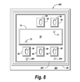
- FIGS. 6 and 8 are views of reactant sides of flow plates of electrochemical pumps according to different embodiments of the invention.
- FIGS. 7 and 9 are views of coolant sides of flow plates of electrochemical pumps according to different embodiments of the invention.
- FIG. 10 is a cross-sectional view taken along line 10 - 10 of FIG. 2 according to an embodiment of the invention.
- FIG. 1 depicts an electrochemical cell stack 10 in accordance with some embodiments of the invention.
- the electrochemical cell stack 10 may be used to form a fuel cell stack that produces electrical power, an electrolyzer or an electrochemical pump (a hydrogen pump, for example), depending on the particular embodiment of the invention.
- the stack 10 Regardless of the configuration of the electrochemical cell stack 10 , the stack 10 generally contains electrochemical cells, each of which is formed from a repeating cell unit 12 .
- each cell unit 12 may be a two plate design that includes an anode cooler plate 14 and a cathode cooler plate 16 .
- the anode cooler plate 14 When used as a fuel cell stack, the anode cooler plate 14 has a bottom surface that contains flow channels for purposes of communicating fuel to a membrane electrode assembly (MEA) of a particular fuel cell. An oxidant flow is communicated to the other side of the MEA through flow channels that are formed in an upper surface of the adjacent cathode cooler plate 16 .
- the bottom surface of the cathode cooler plate 16 and the upper surface of the anode cooler plate 14 contain coolant flow channels for purposes of circulating a coolant through the stack 10 .
- electrochemical cells may be formed from other designs, such as a three flow plate design, for example, in accordance with some embodiments of the invention.
- coolant channels may be spaced farther apart in the stack 10 .
- FIG. 2 depicts a side, or surface 51 , of an exemplary flow plate 50 .
- the flow plate 50 is used for purposes of forming a fuel cell, although the flow plate 50 may also be used for other purposes, such as forming an electrochemical pump cell or an electrolyzer cell, depending on the particular embodiment of the invention.
- the surface 51 is associated with a reactant flow, such as an oxidant flow or a fuel flow (hydrogen flow, for example).
- a reactant flow such as an oxidant flow or a fuel flow (hydrogen flow, for example).
- the surface 51 may be the lower surface of the anode cooler plate 14 (and thus, be associated with a fuel flow); or, alternatively, the surface 51 may be the upper surface of the cathode cooler plate 16 (and thus, may be associated with an oxidant flow).
- the flow plate 50 includes an active area 70 that has flow channels (serpentine flow channels, for example, which are not shown) to communicate the reactant flow to an MEA (not shown) that resides next to the active area 70 between the flow plate 50 and the adjacent flow plate.
- flow channels serpentine flow channels, for example, which are not shown
- the reactant and coolant flows are routed between inlet and outlet plenum passageways of the stack.
- the input and output plenums are formed from openings of the flow plates of the stack.
- FIG. 2 depicts openings 52 , 54 and 56 that form respective portions of the inlet plenum passageways of the stack.
- the opening 52 may form part of the oxidant inlet plenum passageway;
- the opening 54 may form part of the coolant inlet plenum passageway, and
- the opening 56 may form part of the fuel inlet plenum passageway.
- FIG. 2 also depicts openings 58 , 60 and 62 that may be associated with the outlet plenum passageways of the stack.
- the opening 58 may form part of the fuel outlet plenum passageway;
- the opening 60 may form part of the coolant outlet plenum passageway; and the opening 62 may form part of the oxidant outlet plenum passageway.
- the surface 51 is associated with a fuel flow, a fuel flow that is routed from the fuel inlet plenum passageway of the stack, through the active area 70 and into the fuel outlet plenum passageway. More specifically, an incoming fuel flow enters the active area 70 through an opening 71 (called a “dive-through”) that is in communication with the opening 56 . The incoming fuel flows through the flow channels of the active area 70 and exits the active area 70 through another opening 72 , or dive-through, to enter the fuel outlet plenum passageway, which is in communication with the opening 58 .
- the openings 71 and 72 are sized to work in conjunction with the incoming fuel flow to build up a relatively high pressure in the fuel inlet plenum passageway and in the active area 70 .
- this pressure may be in the range of 600 to 10,000 pounds per square inch (psi), depending on the particular embodiment of the invention. It is noted that other pressures may be used in accordance with other embodiments of the invention.
- the flow plate 50 includes a seal 68 that generally surrounds the opening 56 and a seal 74 that generally surrounds the active area 70 .
- the seals 68 and 74 are primary seals that are designed to define outer boundaries so that the reactant flow is contained within. However, under relatively high pressure, leakage may occur, and thus, fuel may escape outside of the primary seals 68 and 74 .
- primary seals 68 and 74 may be planar gasket-type seals, in accordance with some embodiments of the invention, although other seals are possible and are within the scope of the appended claims.
- An outer secondary seal 80 is located on the flow plate 50 surrounds the primary seals 68 and 74 for purposes of forming a backup seal for the primary seals 68 and 74 .
- the secondary seal 80 may be insufficient in that if not for the features that are described herein, pressure may build up from accumulated leakage from the primary seals 68 and 74 to eventually cause leakage from the secondary seal 80 .
- the flow plate 50 includes at least one opening 92 , or dive-through, that is located inside the region sealed by the secondary seal 80 and outside of the regions sealed by the primary seals 68 and 74 .
- the opening 92 extends through the flow plate 50 from the upper reactant surface 51 to the lower surface 52 , which is depicted in FIG. 3 .
- the opening 92 is in fluid communication with the opening 58 . More specifically, as shown in FIG. 3 , a seal 100 extends around the periphery of the opening 58 and the opening 92 . Therefore, any fuel leakage flows from the upper surface 51 through the opening 92 and into the opening 58 via the seal provided by the seal 100 . As a result, any leakage is communicated into the anode exhaust stream. Thus, leakage is contained internally within the stack, pressure on the second seal 80 is minimized and any leakage is routed to the stack's anode exhaust flow.
- a leakage channel 90 is formed in the upper surface 51 of the flow plate 50 .
- the channel 90 is located inside the region defined by the secondary seal 80 and circumscribes the region that includes the primary seals 68 and 74 . Therefore, any fuel leakage from the primary seals 68 and 74 flows into the channel 90 and is routed (due to the relative low pressure present at the opening 92 ) to the opening 92 .
- a layer 93 extends from the active area 70 and outside of the secondary seal 80 near the perimeter of the flow plate 50 .
- the layer 93 may be formed from an extension of the membrane of the MEA that extends to the edges of the flow plate 50 , in accordance with some embodiments of the invention.
- the layer 93 may be a separate layer that is formed from a plastic border, such as kynar, which extends to the edges of the flow plate 50 .
- the layer 93 extends beneath the primary seal 80 to seal any leakage inside the seal 80 .
- the seal that is formed by the layer 93 may be unnecessary, and for these embodiments of the invention, the layer 93 is not included in the stack.
- primary seals 68 may be formed around the other plate openings 52 , 54 , 60 and 62 .
- similar seals 100 may be formed around the openings 53 , 56 , 58 and 62 .
- another seal 110 surrounds the coolant openings 54 and 60 and a coolant flow area 112 .
- the seal 100 around the opening 56 extends around the opening 71 (see also FIG. 2 ) in the active area 70 .
- incoming fuel flow is routed through the opening 56 into the opening 71 and to the active region 70 .
- the exit opening 72 of the active region 70 is surrounded by the seal 100 that also surrounds the opening 58 .
- the opening 92 is also contained within the same seal 100 for purposes of routing any leakage into the fuel exhaust flow.
- the above-described flow plates and seals may be used to form an electrochemical cell stack, such as an exemplary power producing fuel cell stack 151 that is depicted in FIG. 4 .
- the fuel cell stack 151 is part of a fuel cell system 150 .
- the fuel cell stack 151 includes an oxidant inlet 152 that receives an incoming oxidant flow from an oxidant source 76 .
- the incoming oxidant flow flows through the cathode chamber of the fuel cell stack 151 and to an oxidant exhaust 158 .
- the “cathode chamber” refers to the oxidant inlet and outlet plenum passageways as well as the oxidant flow plate channels of the fuel cell stack 16 .
- the oxidant exhaust may be routed to an oxidizer, may be routed to a reformer, may be routed back to an anode inlet 154 (described below), etc., depending on the particular embodiment of the invention.
- the fuel cell stack 151 also includes an anode inlet 154 that receives an incoming fuel flow from a fuel source 180 .
- the fuel source 180 may include a reformer with a compressor; may be a pressurized hydrogen tank; etc., depending on the particular embodiment of the invention.
- the incoming fuel flow is communicated through the anode chamber of the fuel cell stack 151 and exits the stack 10 at an anode exhaust outlet 160 .
- the “anode chamber” refers to the fuel inlet and outlet plenum passageways as well as the anode flow channels of the fuel cell stack 151 .
- the anode exhaust may be routed through an oxidizer 170 that produces an output flow and an outlet 172 of the oxidizer 170 .
- the fuel cell stack 151 may be coupled to a coolant subsystem 175 that circulates a coolant through the stack 151 for purposes of regulating its temperature.
- the fuel cell stack 151 may be used to produce electrical power (delivered at output terminals 177 ) to an electrical load 180 .
- the above-described leakage control may be applied to other types of electrochemical cells, other than fuel cells that produce electricity. More specifically, referring to FIG. 5 , in accordance with some embodiments of the invention, the above-described leakage control may be applied to an electrochemical cell pump 200 .
- the electrochemical pump 200 may be formed from a stack of electrochemical cells, similar to a fuel cell stack that produces electricity. However, unlike the fuel cell stack, the electrochemical pump 200 receives an applied voltage current (across its stack terminals 201 ) and produces a significantly pure fuel flow at its cathode chamber outlet 206 in response to an incoming reformate flow at its anode inlet 202 .
- the stack that forms the electrochemical pump 200 may use dive-through openings in its flow plates for purposes of controlling the leakage from the cathode chamber, the chamber that contains the relatively pure fuel flow.
- This leakage may, depending on the particular embodiment of the invention, either be directed to the anode exhaust or the cathode exhaust of the electrochemical pump 200 .
- FIG. 6 depicts a side, or surface 212 of an exemplary flow plate 210 of the electrochemical cell pump 200 according to an embodiment of the invention.
- the flow plate 210 may generally have the same design as the flow plate 50 (see FIG. 2 ), with like reference numerals being used.
- the flow plates 50 and 210 differ in the following manner.
- the electrochemical cell pump 200 does not have a cathode inlet passageway in its input plenum
- the flow plate 210 does not include the opening 52 or the associated seal 68 .
- the flow plate 210 instead of having an opening 92 that opens into the anode exhaust flow, the flow plate 210 has an opening 204 to remove leakage that might occur from the cathode chamber.
- any leakage outside the primary seal 74 or the seal 68 that surrounds the opening 62 is routed to the opening 204 , an opening that is in communication with the cathode exhaust.
- the flow plate 210 may also include a groove 216 that extends around the seals 68 and 74 and inside the for purposes of routing leakage to the opening 204 .
- the opening 204 is located inside a seal 100 that surrounds the cathode exhaust opening 62 .
- all leakage flow occurs to the cathode exhaust.
- a flow plate 250 has a similar design to the flow plate 210 (see FIG. 6 ) with like reference numerals being used, except that the flow plate 250 includes an opening 260 (that replaces the opening 204 ) that communicates leakage from the cathode chamber into the anode exhaust. More particularly, the opening 260 is in communication with the anode exhaust opening 58 . A channel 261 is formed in the flow plate 250 for purposes of routing the leakage to the opening 260 . As depicted in FIG. 9 of the other opposite side, or surface 252 of the flow plate 250 , the opening 260 is in fluid communication with the anode exhaust opening because the openings 58 and 260 are located inside a seal 100 .
Landscapes
- Chemical & Material Sciences (AREA)
- Engineering & Computer Science (AREA)
- Electrochemistry (AREA)
- Chemical Kinetics & Catalysis (AREA)
- Sustainable Development (AREA)
- Sustainable Energy (AREA)
- Life Sciences & Earth Sciences (AREA)
- Manufacturing & Machinery (AREA)
- General Chemical & Material Sciences (AREA)
- Materials Engineering (AREA)
- Metallurgy (AREA)
- Organic Chemistry (AREA)
- Fuel Cell (AREA)
Abstract
Description
Anode: H2→2H++2e − Equation 1
Cathode: O2+4H++4e −→2H2O Equation 2
Anode: 2H2O→O2+4H++4e − Equation 3
Cathode: 4H++4e −→2H2 Equation 4
Claims (7)
Priority Applications (1)
| Application Number | Priority Date | Filing Date | Title |
|---|---|---|---|
| US11/656,839 US8420256B2 (en) | 2007-01-23 | 2007-01-23 | Controlling leakage in an electrochemical cell |
Applications Claiming Priority (1)
| Application Number | Priority Date | Filing Date | Title |
|---|---|---|---|
| US11/656,839 US8420256B2 (en) | 2007-01-23 | 2007-01-23 | Controlling leakage in an electrochemical cell |
Publications (2)
| Publication Number | Publication Date |
|---|---|
| US20080176136A1 US20080176136A1 (en) | 2008-07-24 |
| US8420256B2 true US8420256B2 (en) | 2013-04-16 |
Family
ID=39641581
Family Applications (1)
| Application Number | Title | Priority Date | Filing Date |
|---|---|---|---|
| US11/656,839 Active 2030-07-01 US8420256B2 (en) | 2007-01-23 | 2007-01-23 | Controlling leakage in an electrochemical cell |
Country Status (1)
| Country | Link |
|---|---|
| US (1) | US8420256B2 (en) |
Cited By (1)
| Publication number | Priority date | Publication date | Assignee | Title |
|---|---|---|---|---|
| US11482714B2 (en) * | 2017-12-13 | 2022-10-25 | Commissariat A L'energie Atomique Et Aux Energies Alternatives | System including a fuel cell having a protons exchanging membrane limiting fuel leakage |
Citations (2)
| Publication number | Priority date | Publication date | Assignee | Title |
|---|---|---|---|---|
| US7659022B2 (en) * | 2006-08-14 | 2010-02-09 | Modine Manufacturing Company | Integrated solid oxide fuel cell and fuel processor |
| US7776490B2 (en) | 2003-08-28 | 2010-08-17 | Honda Motor Co., Ltd. | Fuel cell having closure seal |
-
2007
- 2007-01-23 US US11/656,839 patent/US8420256B2/en active Active
Patent Citations (2)
| Publication number | Priority date | Publication date | Assignee | Title |
|---|---|---|---|---|
| US7776490B2 (en) | 2003-08-28 | 2010-08-17 | Honda Motor Co., Ltd. | Fuel cell having closure seal |
| US7659022B2 (en) * | 2006-08-14 | 2010-02-09 | Modine Manufacturing Company | Integrated solid oxide fuel cell and fuel processor |
Cited By (1)
| Publication number | Priority date | Publication date | Assignee | Title |
|---|---|---|---|---|
| US11482714B2 (en) * | 2017-12-13 | 2022-10-25 | Commissariat A L'energie Atomique Et Aux Energies Alternatives | System including a fuel cell having a protons exchanging membrane limiting fuel leakage |
Also Published As
| Publication number | Publication date |
|---|---|
| US20080176136A1 (en) | 2008-07-24 |
Similar Documents
| Publication | Publication Date | Title |
|---|---|---|
| US7799482B2 (en) | Stack of generators and fuel cell system having the same | |
| CA2442436C (en) | Fuel cell | |
| US7759014B2 (en) | Fuel cell having a seal member | |
| JP5318382B2 (en) | Fuel cell stack | |
| JP2004087497A (en) | Fuel cell stack and fuel cell module | |
| KR102055514B1 (en) | Assembly method and arrangement for a cell system | |
| KR100571821B1 (en) | Direct methanol fuel cell and portable computer having the same | |
| US20090123795A1 (en) | Condensate drainage subsystem for an electrochemical cell system | |
| US7572538B2 (en) | Fuel cell | |
| JP4733915B2 (en) | Fuel cell | |
| JP2005317311A (en) | Fuel cell stack | |
| JP4214027B2 (en) | Fuel cell | |
| US8420256B2 (en) | Controlling leakage in an electrochemical cell | |
| JP4109569B2 (en) | Fuel cell | |
| US6355371B1 (en) | Profiled fuel cell flow plate gasket | |
| US6599650B2 (en) | Fuel cell sealant design | |
| JP5046615B2 (en) | Fuel cell | |
| JP3866246B2 (en) | Fuel cell | |
| KR20200086531A (en) | Fuel cell stack | |
| EP4273973A2 (en) | Separator for fuel cell and fuel cell stack | |
| US20220407104A1 (en) | Fuel cell manifold and fuel cell stack including the same | |
| US20060134495A1 (en) | Fuel cell system with cathode stream recirculation | |
| JP2008171587A (en) | Fuel cell system | |
| KR101122574B1 (en) | Fuel cell system, stack and separator used thereto | |
| KR20240003986A (en) | Plate type manifold for fuel cell and fuel cell system, fabricating method of the same |
Legal Events
| Date | Code | Title | Description |
|---|---|---|---|
| AS | Assignment |
Owner name: HONDA MOTOR CO., LTD., JAPAN Free format text: ASSIGNMENT OF ASSIGNORS INTEREST;ASSIGNORS:BALLATINE, ARNE W.;KIRCHHOFF, DAVID;GORDON, MICHAEL P.;REEL/FRAME:018839/0683;SIGNING DATES FROM 20060607 TO 20061215 Owner name: HONDA MOTOR CO., LTD., JAPAN Free format text: ASSIGNMENT OF ASSIGNORS INTEREST;ASSIGNORS:BALLATINE, ARNE W.;KIRCHHOFF, DAVID;GORDON, MICHAEL P.;SIGNING DATES FROM 20060607 TO 20061215;REEL/FRAME:018839/0683 |
|
| STCF | Information on status: patent grant |
Free format text: PATENTED CASE |
|
| FEPP | Fee payment procedure |
Free format text: PAYOR NUMBER ASSIGNED (ORIGINAL EVENT CODE: ASPN); ENTITY STATUS OF PATENT OWNER: LARGE ENTITY |
|
| FPAY | Fee payment |
Year of fee payment: 4 |
|
| MAFP | Maintenance fee payment |
Free format text: PAYMENT OF MAINTENANCE FEE, 8TH YEAR, LARGE ENTITY (ORIGINAL EVENT CODE: M1552); ENTITY STATUS OF PATENT OWNER: LARGE ENTITY Year of fee payment: 8 |