US8417159B2 - Powder container and image forming apparatus - Google Patents
Powder container and image forming apparatus Download PDFInfo
- Publication number
- US8417159B2 US8417159B2 US12/814,079 US81407910A US8417159B2 US 8417159 B2 US8417159 B2 US 8417159B2 US 81407910 A US81407910 A US 81407910A US 8417159 B2 US8417159 B2 US 8417159B2
- Authority
- US
- United States
- Prior art keywords
- powder containing
- powder
- image forming
- forming apparatus
- containing portion
- Prior art date
- Legal status (The legal status is an assumption and is not a legal conclusion. Google has not performed a legal analysis and makes no representation as to the accuracy of the status listed.)
- Active, expires
Links
Images


Classifications
-
- G—PHYSICS
- G03—PHOTOGRAPHY; CINEMATOGRAPHY; ANALOGOUS TECHNIQUES USING WAVES OTHER THAN OPTICAL WAVES; ELECTROGRAPHY; HOLOGRAPHY
- G03G—ELECTROGRAPHY; ELECTROPHOTOGRAPHY; MAGNETOGRAPHY
- G03G15/00—Apparatus for electrographic processes using a charge pattern
- G03G15/06—Apparatus for electrographic processes using a charge pattern for developing
- G03G15/08—Apparatus for electrographic processes using a charge pattern for developing using a solid developer, e.g. powder developer
- G03G15/0822—Arrangements for preparing, mixing, supplying or dispensing developer
- G03G15/0877—Arrangements for metering and dispensing developer from a developer cartridge into the development unit
- G03G15/0881—Sealing of developer cartridges
- G03G15/0886—Sealing of developer cartridges by mechanical means, e.g. shutter, plug
-
- G—PHYSICS
- G03—PHOTOGRAPHY; CINEMATOGRAPHY; ANALOGOUS TECHNIQUES USING WAVES OTHER THAN OPTICAL WAVES; ELECTROGRAPHY; HOLOGRAPHY
- G03G—ELECTROGRAPHY; ELECTROPHOTOGRAPHY; MAGNETOGRAPHY
- G03G15/00—Apparatus for electrographic processes using a charge pattern
- G03G15/06—Apparatus for electrographic processes using a charge pattern for developing
- G03G15/08—Apparatus for electrographic processes using a charge pattern for developing using a solid developer, e.g. powder developer
- G03G15/0822—Arrangements for preparing, mixing, supplying or dispensing developer
- G03G15/0865—Arrangements for supplying new developer
- G03G15/0867—Arrangements for supplying new developer cylindrical developer cartridges, e.g. toner bottles for the developer replenishing opening
- G03G15/0868—Toner cartridges fulfilling a continuous function within the electrographic apparatus during the use of the supplied developer material, e.g. toner discharge on demand, storing residual toner, acting as an active closure for the developer replenishing opening
-
- G—PHYSICS
- G03—PHOTOGRAPHY; CINEMATOGRAPHY; ANALOGOUS TECHNIQUES USING WAVES OTHER THAN OPTICAL WAVES; ELECTROGRAPHY; HOLOGRAPHY
- G03G—ELECTROGRAPHY; ELECTROPHOTOGRAPHY; MAGNETOGRAPHY
- G03G15/00—Apparatus for electrographic processes using a charge pattern
- G03G15/06—Apparatus for electrographic processes using a charge pattern for developing
- G03G15/08—Apparatus for electrographic processes using a charge pattern for developing using a solid developer, e.g. powder developer
- G03G15/0822—Arrangements for preparing, mixing, supplying or dispensing developer
- G03G15/0865—Arrangements for supplying new developer
- G03G15/0867—Arrangements for supplying new developer cylindrical developer cartridges, e.g. toner bottles for the developer replenishing opening
- G03G15/087—Developer cartridges having a longitudinal rotational axis, around which at least one part is rotated when mounting or using the cartridge
- G03G15/0872—Developer cartridges having a longitudinal rotational axis, around which at least one part is rotated when mounting or using the cartridge the developer cartridges being generally horizontally mounted parallel to its longitudinal rotational axis
-
- G—PHYSICS
- G03—PHOTOGRAPHY; CINEMATOGRAPHY; ANALOGOUS TECHNIQUES USING WAVES OTHER THAN OPTICAL WAVES; ELECTROGRAPHY; HOLOGRAPHY
- G03G—ELECTROGRAPHY; ELECTROPHOTOGRAPHY; MAGNETOGRAPHY
- G03G2215/00—Apparatus for electrophotographic processes
- G03G2215/06—Developing structures, details
- G03G2215/066—Toner cartridge or other attachable and detachable container for supplying developer material to replace the used material
- G03G2215/0663—Toner cartridge or other attachable and detachable container for supplying developer material to replace the used material having a longitudinal rotational axis, around which at least one part is rotated when mounting or using the cartridge
- G03G2215/0665—Generally horizontally mounting of said toner cartridge parallel to its longitudinal rotational axis
- G03G2215/0668—Toner discharging opening at one axial end
Definitions
- toner replenishment devices have been proposed, in which toner leakage is securely prevented when the toner replenishment device is detached from a main body of an image forming apparatus.
- FIG. 1 shows an entire configuration of an image forming apparatus, which is a so-called tandem-type digital color printer
- FIG. 2 illustrates image forming units
- FIG. 3 is a perspective view illustrating powder cartridges and a supply mechanism
- FIG. 4 illustrates the powder cartridges
- FIGS. 5A and 5B show a powder cartridge as viewed from a front-end side thereof
- FIG. 6 is a perspective view showing a first shutter
- FIG. 8 illustrates a state of the powder cartridge halfway through the insertion thereof
- FIG. 9 illustrates the powder cartridge in a state after the first shutter moves backwardly, as viewed from the front end portion side of the powder cartridge
- FIG. 10 illustrates the powder cartridge in a state after the insertion thereof into the image forming apparatus is completed
- FIG. 11 illustrates the powder cartridge in a state where the first shutter is closed, as viewed from the bottom portion side of the powder cartridge
- FIG. 15 is a view illustrating periphery of a third flat surface of the accommodation portion
- FIG. 16 is a cross-sectional view taken along the line XVI-XVI in FIG. 15 ;
- FIG. 17 is a cross-sectional view taken along the line XVII-XVII in FIG. 14 ;
- FIG. 18 illustrates a state of each portion immediately after the insertion of the powder cartridge is started
- FIG. 19 is a view illustrating a state of each portion halfway through the insertion of the powder cartridge
- FIG. 20 is a view illustrating a state of each portion after the insertion of the powder cartridge is completed
- FIGS. 21A and 21B are views for illustrating operation of a second protrusion
- FIGS. 22 to 27 are views for illustrating operation of a second shutter and a slidable member
- FIG. 28 illustrates a state where the powder cartridge, which has been inserted with an operation portion placed first, is pulled out
- FIG. 29 illustrates a state where the powder cartridge of the present exemplary embodiment is pulled out.
- FIG. 1 shows an entire configuration of an image forming apparatus 1 , which is a so-called tandem-type digital color printer.
- the image forming apparatus 1 shown in FIG. 1 includes: an image forming system 10 forming an image corresponding to gradation data of each color; a sheet transport system 40 transporting a sheet P as an example of a recording medium; an image processing portion (not shown) executing predetermined image processing on image data received from a personal computer (PC) or a document scanning device, which are not shown, connected to the image processing portion; and a controlling portion (not shown) controlling operation of each part (each device).
- PC personal computer
- a document scanning device which are not shown
- the transfer unit 20 includes: a driving roller 22 that drives the intermediate transfer belt 21 ; tension rollers 23 that apply a constant tension to the intermediate transfer belt 21 ; a backup roller 24 for performing secondary transfer of the superimposed powder images of respective colors onto the sheet P; and a belt cleaner 25 that removes residual powder remaining on the intermediate transfer belt 21 .
- the intermediate transfer belt 21 is wound around the driving roller 22 , the tension rollers 23 and the backup roller 24 with a constant tension, and circularly driven by the driving roller 22 in a direction of an arrow in the figure at a predetermined speed.
- Each of the image forming units 11 Y, 11 M, 11 C and 11 K includes, taking the image forming unit 11 Y for yellow color as an example for explanation: a photoconductive drum 12 Y; a charging device 13 Y for charging the photoconductive drum 12 Y; and a developing device 16 Y that develops the electrostatic latent image formed on the photoconductive drum 12 Y by a laser beam LB-Y emitted from the laser exposure device 30 .
- a main part of the charging device 13 Y is constituted by a charging roller 14 Y arranged in contact with the photoconductive drum 12 Y and a cleaning roller 15 Y that cleans the charging roller 14 Y.
- the formed electrostatic latent image is developed into a powder image of each of the color components yellow (Y), magenta (M), cyan (C) and black (K) in each of the image forming units 11 Y, 11 M, 11 C and 11 K, respectively. Then, the powder images formed on the photoconductive drums 12 in the image forming units 11 Y, 11 M, 11 C and 11 K are multiply-transferred onto the intermediate transfer belt 21 .
- FIG. 3 is a perspective view illustrating powder cartridges 200 Y, 200 M, 200 C, 200 K and the supply mechanism 100 .
- the supply mechanism 100 in the present exemplary embodiment is provided with accommodation portions 500 that are corresponding to the respective powder cartridges 200 Y, 200 M, 200 C and 200 K and accommodate the respective powder cartridges 200 Y, 200 M, 200 C and 200 K.
- a powder transport portion 800 is provided to transport the powder discharged from the powder cartridges 200 Y, 200 M, 200 C and 200 K accommodated in the accommodation portions 500 to the developing device 16 Y, 16 M, 16 C and 16 K.
- the powder cartridges 200 Y, 200 M, 200 C and 200 K are configured to be inserted into the image forming apparatus 1 from the front side to the rear side thereof.
- the powder cartridges 200 Y, 200 M, 200 C and 200 K are also configured to be detached from the image forming apparatus 1 by pulling the cartridges toward the front side of the image forming apparatus 1 .
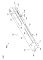
- FIG. 4 illustrates the powder cartridges 200 Y, 200 M, 200 C and 200 K.
- the powder cartridges 200 Y, 200 M, 200 C and 200 K have the same configuration, and therefore the powder cartridge 200 Y is taken as an example in the explanation below.
- the powder cartridge 200 Y is formed to be cylindrical and to have a predetermined length. More specifically, the powder cartridge 200 Y includes an operation portion 200 which is operated by a user when the powder cartridge 200 Y is attached to and detached from the image forming apparatus 1 and a main body portion 300 (an example of a powder containing portion) which is formed to be cylindrical with an end portion and the other end portion, and contains the powder inside thereof.
- a main body portion 300 an example of a powder containing portion
- the main body portion 300 includes a base 330 (an example of a powder containing portion) which is cylindrical and contains the powder inside thereof, and rotation regulation portions 340 provided to project from an outer circumferential surface of the base 330 along the axial direction of the powder cartridge 200 Y in contact with the accommodation portion 500 for regulating the rotation of the powder cartridge 200 Y in a circumferential direction.
- the main body portion 300 also includes a first shutter 310 (an example of a covering member) provided to be movable on a movement route along with the axial direction of the powder cartridge 200 Y and facing a second shutter 320 (described later) to cover the second shutter 320 , and a shutter guide portion 350 that guides the first shutter 310 and the second shutter 320 when these shutters move.
- FIGS. 5A and 5B show the powder cartridge 200 Y as viewed from the front-end side thereof. More specifically, these figures show the powder cartridge 200 Y as viewed from the direction of arrow V in FIG. 4 .
- a memory 301 is mounted to the powder cartridge 200 Y.
- the memory 301 for example, information regarding powder use status, information regarding powder color, information regarding a contained amount of powder, information regarding powder manufacture, and the like are stored.
- the powder cartridge 200 Y is provided with a connecting member 302 that is connected to a connected member 810 (refer to FIG. 17 ) provided to the image forming apparatus 1 side when the powder cartridge 200 Y is attached to the image forming apparatus 1 , and receives a driving force from the image forming apparatus 1 side.
- each rotation regulation portion 340 has the first projection portion 341 extending from the tip portion of the base portion 343 in one direction and the second projection portion 342 extending from the tip portion of the base portion 340 in a direction opposite to the one direction. Further, in other words, each rotation regulation portion 340 includes the first projection portion 341 that is arranged to face the outer circumferential surface of the base 330 with a gap therebetween, as well as being arranged along a direction in which a tangential line to the outer circumferential surface of the base 330 extends.
- FIG. 5B shows a cross-sectional view of the rotation regulation portion 340 taken along the lines VB 1 -VB 1 and VB 2 -VB- 2 in FIG. 4 , and as shown in the figure, the central portion and the rear end portion of the powder cartridge 200 Y in the longitudinal direction are formed to have L-shaped cross-section.
- the above-described first projection portion 341 is not provided to the central portion and the rear end portion, but the base portion 343 and the second projection portion 342 constitute the rotation regulation portion 340 .
- the first shutter 310 includes a swing piece 315 D which has elasticity and is swingable upwardly and downwardly in the figure on each of the first side wall 311 and the second side wall 312 , and further includes a fourth protrusion 315 E provided on a tip portion of the swing piece 315 D to protrude outward of the first shutter 310 .
- FIG. 7 shows a state of the powder cartridge 200 Y immediately after the insertion of the powder cartridge 200 Y into the image forming apparatus 1 is started.
- FIG. 8 shows a state of the powder cartridge 200 Y halfway through the insertion of the powder cartridge 200 Y into the image forming apparatus 1 .
- the powder cartridge 200 Y has a regulation protrusion 303 which is provided at a lower portion of the base 330 to strike the fourth protrusion 315 E provided to the first shutter 310 for regulating backward movement of the first shutter 310 .
- the fourth protrusion 315 E strikes the regulation protrusion 303 , thus going into a state where the backward movement of the first shutter 310 is regulated.
- the third protrusion 315 C (refer to FIG.
- the third protrusion 315 C is located between the upper edge portion 321 and the outer circumferential surface of the base 330 ), thus regulating movement of the first shutter 310 in a direction away from the base 330 .
- the fourth protrusion 315 E is pressed by the accommodation portion 500 (refer to FIG. 3 ) in the direction away from the base 330 (lower right direction in the figure) and in the direction that the first shutter 310 moves backwardly (lower left direction in the figure) (described in detail later). Accordingly, the above-described striking between the fourth protrusion 315 E and the regulation protrusion 303 is removed, and the first shutter 310 moves backwardly to a predetermined position.
- the powder cartridge 200 Y further proceeds inwardly of the image forming apparatus 1 , but movement of the first shutter 310 is regulated by the accommodation portion 500 , and thus the first shutter 310 stops at a predetermined position of the accommodation portion 500 . Consequently, as shown in FIG. 8 , the second shutter 320 provided on the front end side and the lower side of the powder cartridge 200 Y is exposed. After the striking between the upper edge portion 321 of the second shutter 320 and the third protrusion 315 C is removed, the second protrusion 315 B (refer to FIG. 6 ) comes to strike the inner wall of the first guide groove 351 provided to the shutter guide portion 350 . Thereby, the displacement (hanging down) of the first shutter 310 stops at a predetermined position.
- a part positioned at the front end portion of the powder cartridge 200 Y is provided with a chamfered flat surface 331 .
- the flat surface 331 is provided with a protrusion 332 that protrudes in a direction away from the flat surface 331 .
- the protrusion 332 is provided closer to the front end portion of the powder cartridge 200 Y than the shutter guide portion 350 (refer to FIG. 8 ).
- the shutter guide portion 350 includes: a guide main body portion 352 that projects in the radial direction of the base 330 from the outer circumferential surface of the base 330 and is provided along the axial direction of the powder cartridge 200 Y; and a first protrusion 353 that protrudes from one side surface of the guide main body portion 352 and extends along the axial direction of the powder cartridge 200 Y.
- the second shutter 320 is arranged to face an outer surface of the base 330 .
- the second shutter 320 has: a closing portion 323 that is formed to be flat and arranged to face the sealing member 304 to cover the through hole 304 A formed on the sealing member 304 ; a first side portion 327 that extends from one end portion of the closing portion 323 in the width direction thereof toward the base 330 ; a second side portion 322 that extends from the other end portion toward the base 330 ; a first facing portion 324 that is connected to the first side portion 327 and arranged to face the closing portion 323 ; and a second facing portion 325 that is connected to the second side portion 322 and arranged to face the closing portion 323 .
- the first protrusion 353 and the sealing member 304 are held between the first facing portion 324 and the closing portion 323
- the second protrusion 354 and the sealing member 304 are held between the second facing portion 325 and the closing portion 323 . Accordingly, the sealing member 304 is in a state of being compressed.
- a powder discharge port 307 through which the powder is sequentially discharged is formed on the lower portion of the powder cartridge 200 Y. It should be noted that, when the second shutter 320 moves with respect to the base 330 , the second shutter 320 moves on the movement route along the axial direction of the powder cartridge 200 Y.
- the above-described operation is executed in reverse order. That is, the powder discharge port 307 is closed by relative proceeding of the second shutter 320 against the main body portion 300 of the powder cartridge 200 Y. Further, by relative proceeding of the first shutter 310 , the second shutter 320 is covered with the first shutter 310 .
- a slope 326 which is provided to be connected to the upper edge portion 321 and approaches the base 330 along with a move toward the front end portion of the powder cartridge 200 Y, is formed on the second shutter 320 .
- the third protrusion 315 C (refer to FIG. 6 ) provided to the first shutter 310 goes on the slope 326 . Accordingly, the front end portion of the first shutter 310 approaches the base 330 and the second shutter 320 is covered with the first shutter 310 .
- a shutter guide groove 356 (an example of a recess portion) is formed along the axial direction of the powder cartridge 200 Y.
- a first retraction portion 357 A and a second retraction portion 357 B are provided to press a first protrusion (described in detail later) provided to the accommodation portion 500 (refer to FIG. 3 ) to retract the first protrusion from a movement route of the powder cartridge 200 Y.
- a first protrusion described in detail later
- a third retraction portion 357 C (another example of the pressing portion) is also provided inside the shutter guide groove 356 to press a second protrusion (described in detail later) provided to the accommodation portion 500 to retract the second protrusion from the movement route of the powder cartridge 200 Y.
- a second protrusion (described in detail later) provided to the accommodation portion 500 to retract the second protrusion from the movement route of the powder cartridge 200 Y.
- Each of the first retraction portion 357 A, the second retraction portion 35713 and the third retraction portion 357 C is formed to have plural (ribbed) protrusions like thin plates arranged in parallel with each other.
- the first retraction portion 357 A as an example of a retraction unit is provided to a side of the powder cartridge 200 Y, where the operation portion 200 is provided. In the case where the powder cartridge 200 Y is viewed from the bottom portion side thereof (in the state shown in FIG. 11 ), the first retraction portion 357 A is provided adjacent to the operation portion 200 .
- the second retraction portion 357 B is provided between the first retraction portion 357 A and the third retraction portion 357 C.
- the second retraction portion 3578 is provided closer to the rear end portion of the powder cartridge 200 Y than the first shutter 310 when the first shutter 310 is closed (refer to FIG. 11 ). Further, when the first shutter 310 is closed, the second retraction portion 35713 is provided adjacent to the first shutter 310 (refer to FIG. 11 ).
- the third retraction portion 357 C is provided on the front end portion side of the powder cartridge 200 Y. Further, when the second shutter 320 is closed, the third retraction portion 357 C is provided closer to the rear end portion of the powder cartridge 200 Y than the second shutter 320 (refer to FIG. 12 ). Further, as the powder cartridge 200 Y is viewed from the bottom portion side thereof, the third retraction portion 357 C is provided adjacent to the second shutter 320 (refer to FIG. 12 ).
- the first retraction portion 357 A has a slope (an inclined surface) A 1 that is formed to be apart from the outer circumferential surface (outer surface) of the base 330 along with a move toward the rear end portion side of the powder cartridge 200 Y.
- the first retraction portion 357 A has a slope inclined to the withdrawal direction of the powder cartridge 200 Y.
- the second retraction portion 357 B has a slope B 1 that is formed to be apart from the outer circumferential surface of the base 330 along with a move toward the front end portion side of the powder cartridge 200 Y.
- the second retraction portion 35713 is provided between the outer surface of the base 330 and the movement route of the first shutter 310 .
- the third retraction portion 357 C also has a slope C 1 that is formed to be apart from the outer circumferential surface of the base 330 along with a move toward the front end portion side of the powder cartridge 200 Y.
- the third retraction portion 357 C is provided between the outer surface of the base 330 and the movement route of the second shutter 320 .
- FIG. 13 also shows the inside of the main body portion 300 . Inside the main body portion 300 , a transport member 305 is provided, which is driven to rotate on receiving the driving force from the connecting member 302 for transporting the powder inside the main body portion 300 to the powder discharge port 307 (refer to FIG. 10 ).
- FIG. 14 is a perspective view of the accommodation portion 500 .
- the accommodation portion 500 has, on an upper edge of the first side wall 510 , a first guide 540 into which one of the rotation regulation portions 340 (refer to FIG. 5A ) formed on the powder cartridge 200 Y is inserted, and which guides the one of the rotation regulation portions 340 .
- the accommodation portion 500 further has, on an upper edge of the second side wall 520 , a second guide 550 into which the other one of the rotation regulation portions 340 (refer to FIG. 5A ) formed on the powder cartridge 200 Y is inserted, and which guides the other one of the rotation regulation portions 340 .
- the accommodation portion 500 includes, on an inner surface of the second side wall 520 , a V-shaped protrusion 560 having a slope 561 that approaches the bottom portion 530 along with proceeding in the insertion direction of the powder cartridge 200 Y. Though illustration thereof is omitted, the protrusion 560 is also provided to an inner surface of the first side wall 510 . Moreover, the accommodation portion has a couple of long holes 565 provided to pass through the second side wall 520 . The couple of long holes 565 are provided in the back side of the accommodation portion 500 in the insertion direction of the powder cartridge 200 Y. The couple of long holes 565 are also provided on the first side wall 510 , although illustration thereof is omitted.
- the bottom portion 530 is provided with three flat surfaces arranged with displacement in a height direction. Specifically, in the bottom portion 530 , a first flat surface 531 is provided near an inlet portion side where the insertion of the powder cartridge 200 Y is started. At the back of the first flat surface 531 , a second flat surface 532 that is positioned lower than the first flat surface 531 is provided. At the further back of the second flat surface 532 , a third flat surface 533 is provided such that the third flat surface 533 is arranged higher than the first flat surface 531 and the second flat surface 532 . A first connecting surface 534 arranged along the height direction to connect the first flat surface 531 and the second flat surface 532 , and a second connecting surface 535 arranged along the height direction to connect the second flat surface 532 and the third flat surface 533 are also provided.
- the first protrusion 571 is enabled to retract from the movement route of the powder cartridge 200 Y by deflection of the elastic piece 571 A
- the second protrusion 572 is also enabled to retract from the movement route of the powder cartridge 200 Y by deflection of the elastic piece 572 A.
- the first protrusion 571 and the second protrusion 572 are provided by forming thereof integrally with the accommodation portion 500 , not by attaching separate members.
- a regulation protrusion 573 is provided at a portion above the second connecting surface 535 where the third flat surface 533 and the second side wall 520 is connected.
- the regulation protrusion 573 makes contact with the operation portion 200 (refer to FIG. 4 ) when the powder cartridge 200 Y is inserted in a state where the front end and the rear end of the powder cartridge 200 Y is reversed, thereby regulating the movement of the powder cartridge 200 Y toward the backside beyond the position where the regulation protrusion 573 is provided.
- the accommodation portion 500 has a main body side discharge port 575 for further discharging powder having been discharged from the powder discharge port 307 (refer to FIG. 10 ) to the powder transport portion 800 (refer to FIG. 3 ).
- FIG. 15 illustrates periphery of the third flat surface 533 of the accommodation portion 500 .
- the accommodation portion 500 is provided with a slidable member 580 arranged backside than the second protrusion 572 in the insertion direction of the powder cartridge 200 Y and above the third flat surface 533 , which is slidable in the insertion direction and withdrawal direction of the powder cartridge 200 Y.
- the accommodation portion 500 is also provided with a main body side shutter 590 that is attached to the slidable member 580 and slidable in the insertion direction and the withdrawal direction of the powder cartridge 200 Y.
- FIG. 16 is a cross-sectional view taken along the line XVI-XVI in FIG. 15 .
- the slidable member 580 will be explained with reference to FIGS. 15 and 16 .
- illustration of the main body side shutter 590 is omitted.
- the slidable member 580 includes: a bottom plate 581 formed to be rectangular as seen in a top view; a side portion 582 arranged on one of the long sides of the bottom plate 581 and extending upwardly; and a facing portion 583 arranged to face the bottom plate 581 and is connected to the side portion 582 .
- the slidable member 580 has a gap 584 between the bottom plate 581 and the facing portion 583 . Though the illustration is omitted in FIG. 16 , the side portion 582 , the facing portion 583 and the gap 584 are provided on the other long side of the bottom plate 581 .
- the slidable member 580 has a couple of facing pieces 585 on one of the long sides of the bottom plate 581 , which are arranged to face the first side wall 510 .
- each of the facing pieces 585 is provided with a protrusion 585 A that protrudes toward the first side wall 510 .
- the protrusion 585 A is inserted into the long hole 565 formed on the accommodation portion 500 (refer to FIG. 14 ). Though illustration in the figure is omitted, the couple of facing pieces 585 are provided to the other long side.
- the slidable member 580 includes, as shown in FIG. 16 , a through hole 586 on the bottom plate 581 , which is arranged to face the main body side discharge port 575 (refer to FIG. 14 ) to pass through the powder having been discharged from the powder cartridge 200 Y.
- a sealing member 587 is put on a surface facing the third flat surface 533 (refer to FIG. 15 ) among the plural surfaces formed in the bottom plate 581 (refer to FIG. 16 ).
- the sealing member 587 has elasticity and is compressible in a thickness direction.
- the sealing member 587 may be formed of, for example, urethane rubber or foamed polyurethane.
- a through hole 587 A is formed to pass through the powder that has been passed through the through hole 586 .
- the slidable member 580 has a slope 583 A that approaches the bottom plate 581 along with a move toward a downstream side of the insertion direction of the powder cartridge 200 Y, the slope 583 A being arranged on a surface facing the bottom plate 581 among the plural surfaces provided to the facing portion 583 and on an upstream side in the insertion direction of the powder cartridge 200 Y.
- a cutout 583 B is formed on the facing portion 583 of the slidable member 580 (also, refer to FIG. 15 ).
- the main body side shutter 590 has a shutter main body 593 , which is contained within the gap 584 of the slidable member 580 and is slidable in the insertion direction and the withdrawal direction of the powder cartridge 200 Y, and a first swing piece 591 swingable in an approaching direction and a separating direction with respect to one of the two facing portions 583 .
- a second swing piece 592 is also provided, which is swingable in an approaching direction and a separating direction with respect to the other one of the two facing portions 583 .
- the first swing piece 591 and the second swing piece 592 are fastened to the upper surface of the shutter main body 593 .
- the main body side shutter 590 has a first protrusion 594 A at a part of the first swing piece 591 facing the second swing piece 592 , and a second protrusion 5948 at a part of the second swing piece 592 facing the first swing piece 591 . Further, the main body side shutter 590 has a third protrusion 594 C which enters into the cutout 58313 formed on one of the facing portions 583 when facing the cutout 58313 , and a fourth protrusion 594 D which enters into the cutout 583 B formed on the other one of the facing portions 583 when facing the cutout 583 B.
- FIG. 17 is a cross-sectional view taken along the line XVII-XVII in FIG. 14 .
- the accommodation portion 500 will be further described using the figure.
- the slidable member 580 and the main body side shutter 590 are also illustrated.
- each of the first protrusion 571 and the second protrusion 572 has a triangular cross-section. More specifically, the first protrusion 571 , as an example of a moving portion and the protruding portion, has a regulation surface 571 E arranged in an orthogonal relationship (intersecting relationship) to the insertion direction (withdrawal direction) of the powder cartridge 200 Y to regulate the backward movement of the first shutter 310 (refer to FIG. 10 ).
- the first protrusion 571 also includes a first slope 571 F which is connected to the regulation surface 571 E and is directed upwardly (in a direction away from the first flat surface 531 ) along with proceeding in the withdrawal direction of the powder cartridge 200 Y.
- the first protrusion 571 has the first slope 571 F as an example of a slope that is inclined toward the withdrawal direction of the powder cartridge 200 Y.
- the first protrusion 571 also has a second slope 571 G which is connected to the first slope 571 F and is directed downwardly (in a direction approaching the first flat surface 531 ) along with proceeding in the withdrawal direction of the powder cartridge 200 Y.
- the second protrusion 572 has a regulation surface 572 E arranged in an orthogonal relationship (intersecting relationship) to the insertion direction (withdrawal direction) of the powder cartridge 200 Y to regulate the backward movement of the second shutter 320 (refer to FIG. 10 ).
- the second protrusion 572 also includes a first slope 572 F which is connected to the regulation surface 572 E and is directed upwardly (in a direction away from the third flat surface 533 ) along with proceeding in the withdrawal direction of the powder cartridge 200 Y.
- the second protrusion 572 has the first slope 572 F as an example of a slope that is inclined toward the withdrawal direction of the powder cartridge 200 Y.
- the second protrusion 572 also has a second slope 572 G which is connected to the first slope 572 F and is directed downwardly (in a direction approaching the third flat surface 533 ) along with proceeding in the withdrawal direction of the powder cartridge 200 Y.
- the powder transport portion 800 includes: a connected member 810 to which the connecting member 302 (refer to FIG. 5A ) provided to the powder cartridge 200 Y and which drives to rotate the connecting member 302 ; a motor (not shown) that drives to rotate the connected member 810 ; a cylindrical member 820 constituting a transport path of the powder; and a transport member 830 which is held in the cylindrical member 820 to transport the powder.
- FIG. 18 illustrates a state of each portion immediately after the insertion of the powder cartridge 200 Y is started.
- the first shutter 310 passes through over the first flat surface 531 .
- the second slope 571 G (refer to FIG. 17 ) is pressed by the first shutter 310 , and thus the first protrusion 571 moves toward the lower surface side of the first flat surface 531 .
- the first protrusion 571 is retracted from the movement route of the powder cartridge 200 Y not to block the movement of the powder cartridge 200 Y.
- the rotation regulation portions 340 (refer to FIG. 5A ) of the powder cartridge 200 Y are inserted into the first guide 540 and the second guide 550 (refer to FIG. 14 ). Accordingly, the powder cartridge 200 Y moves along the predetermined route.
- the first shutter 310 passes through the first protrusion 571 as shown in FIG. 19 (a view illustrating a state of each part halfway through the insertion of the powder cartridge 200 Y). Consequently, the first protrusion 571 protrudes on the movement route of the powder cartridge 200 Y. On this occasion, the first protrusion 571 protrudes within the shutter guide groove 356 (refer to FIG. 11 ) provided on the shutter guide portion 350 .
- the fourth protrusion 315 E of the first shutter 310 strikes the slope 561 of the protrusion 560 provided on the accommodation portion 500 side, and thus proceeding of the first shutter 310 is regulated.
- the fourth protrusion 315 E is pressed from above by the slope 561 , thereby releasing the striking of the fourth protrusion 315 E against the regulation protrusion 303 , as explained by use of FIG. 7 .
- the second protrusion 572 protrudes again on the movement route of the powder cartridge 200 Y.
- the second protrusion 572 protrudes within the shutter guide groove 356 (also, refer to FIG. 11 ), as described above.
- the protrusion 332 (refer to FIGS. 12 and 13 ) provided on the front end portion of the powder cartridge passes between the first protrusion 594 A and the second protrusion 594 B provided to the main body side shutter 590 (refer to FIG. 15 ). Thereby, the protrusion 332 goes into a state to be held in a region surrounded by the first swing piece 591 and the second swing piece 592 .
- the first protrusion 353 (refer to FIG. 9 ), the second protrusion 354 and the sealing member 304 enter into the inside of the gap 584 (refer to FIG. 16 ) formed on the slidable member 580 .
- the sealing member 304 is compressed in the thickness direction.
- an end surface of the shutter main body 593 (refer to FIG. 15 ) is pressed by these members, thereby moving the main body side shutter 590 forward. Accordingly, the main body side discharge port 575 (refer to FIG. 14 ) is opened.
- the bottom plate 581 of the slidable member 580 (refer to FIG. 16 ) is positioned on the movement route of the second shutter 320 . Therefore, after passing through the second protrusion 572 (refer to FIG. 15 ), the second shutter 320 having moved along with insertion of the powder cartridge 200 Y comes to strike the slidable member 580 , and thus the movement thereof is regulated. Consequently, in the present exemplary embodiment, the second shutter 320 is in a state to be held between the slidable member 580 and the second protrusion 572 upon completing insertion of the powder cartridge 200 Y. That is, the second shutter 320 comes to a state to be held in a portion indicated by the broken line in FIG. 15 . In addition, the second shutter 320 relatively moves with respect to the base 330 of the main body portion 300 by striking the slidable member 580 , thereby opening the powder discharge port 307 .
- the third protrusion 594 C and the fourth protrusion 594 D reach the cutout 583 B (refer to FIG. 15 ) as the main body shutter 590 further moves. Therefore, a gap between the first protrusion 594 A and the second protrusion 594 B becomes wider, thus allowing the protrusion 332 to pass between the first protrusion 594 A and the second protrusion 594 B.
- an end portion of the second shutter 320 strikes the regulation surface 572 E of the second protrusion 572 (refer to FIG. 17 ), accordingly, the movement of the second shutter 320 is regulated.
- the second shutter 320 moves on the movement route along the withdrawal direction of the powder cartridge 200 Y. Then the second shutter 320 strikes the second protrusion 572 that protrude into the movement route from a side of the movement route. Accordingly, the second shutter is brought into a state where movement thereof is regulated.
- the powder discharge port 307 (refer to FIG. 10 ) approaches the second shutter 320 , and thus the powder discharge port 307 is closed by the second shutter 320 .
- the third retraction portion 357 C (refer to FIGS. 13 and 20 ) makes contact with the first slope 572 F (refer to FIG. 17 ) of the second protrusion 572 . Accordingly, the second protrusion 572 is retracted from the movement route of the second shutter 320 , and the second shutter 320 then passes through the second protrusion 572 .
- the second protrusion 572 moves toward the side. Accordingly, the second shutter 320 comes to pass through the second protrusion 572 .
- FIGS. 21A and 21B views for illustrating the operation of the second protrusion 572 .
- the slope C 1 of the third retraction portion 357 C provided to the powder cartridge 200 Y makes contact with the first slope 572 F of the second protrusion 572 .
- the second protrusion 572 moves in a direction shown by an arrow (toward the side of the movement route of the second shutter 320 ) in the figure.
- a left end portion (in the figure) of the second shutter 320 further presses the first slope 572 F of the second protrusion 572 having been moved due to pressing by the third retraction portion 357 C, and thereby the second protrusion 572 further moves in the direction shown by the arrow (toward the side of the movement route of the second shutter 320 ) in the figure. Accordingly, the second protrusion 572 is retracted from the movement route of the second shutter 320 , and the second shutter 320 passes through the second protrusion 572 .
- backward movement of the first shutter 310 is also regulated. More specifically, when withdrawal of the powder cartridge 200 Y is performed, an end portion of the first shutter 310 strikes the regulation surface 571 E (refer to FIG. 17 ) of the first protrusion 571 . Consequently, backward movement of the first shutter 310 is regulated, and the first shutter 310 comes to relatively move with respect to the main body portion 300 . When backward movement is regulated, the first shutter 310 is in a state to rest above the second flat surface 532 (refer to FIG. 14 ).
- the third protrusion 315 C (refer to FIG. 6 ) of the first shutter 310 runs upon the slope 326 (refer to FIG. 8 ) formed on the second shutter 320 . Accordingly, the front end portion of the first shutter 310 approaches the outer circumferential surface of the base 330 of the powder cartridge 200 Y. Thereafter, the fourth protrusion 315 E (refer to FIG. 7 ) comes to position forward of the regulation protrusion 303 (refer to FIG. 7 ), and the first shutter 310 is fastened to the base 330 .
- the second retraction portion 357 B presses the first slope 571 F (refer to FIG. 17 ) of the first protrusion 571 . Consequently, the first protrusion 571 is retracted from the movement route of the first shutter 310 . Then the first shutter 310 passes through the first protrusion 571 , and thus withdrawal of the powder cartridge 200 Y is completed.
- the slope B 1 of the second retraction portion 357 B provided to the powder cartridge 200 Y makes contact with the first slope 571 F of the first protrusion 571 . Accordingly, the first protrusion 571 moves in the direction of an arrow (toward the side of the movement route of the first shutter 310 ) in the figure.
- FIGS. 22 to 27 are views for illustrating the operation of the second shutter 320 and the slidable member 580 .
- the second shutter 320 moves in association with movement of the powder cartridge 200 Y, and as shown in FIG. 26 , an end portion of the second shutter 320 strikes the regulation surface 572 E of the second protrusion 572 . Accordingly, movement of the second shutter 320 is temporarily regulated.
- the reason why the second shutter 320 moves in association with movement of the powder cartridge 200 Y is that the sealing member 304 (refer to FIG. 9 ) is provided in a state of being compressed in the thickness direction, and thereby a restoring force of the sealing member 304 is exerted between the first facing portion 324 and the first protrusion 353 , and between the second facing portion 325 and the second protrusion 354 .
- the frictional force is exerted between the first protrusion 353 (refer to FIG. 9 ) and the slidable member 580 (the same holds for the second protrusion 354 ), and between the sealing member 304 (refer to FIG. 9 ) and the slidable member 580 .
- the slidable member 580 is in a state to be held by the powder cartridge 200 Y. Consequently, when the powder cartridge 200 Y is pulled out, the slidable member 580 moves in association with the powder cartridge 200 Y.
- the gap is formed between the second shutter 320 and the slidable member 580 (the part regulating movement of the second shutter 320 ) in pulling out the powder cartridge 200 Y
- the powder fallen from the powder discharge port 307 enters the gap when the powder discharge port 307 passes above the gap afterwards.
- the powder comes to accumulate in the gap. If a new powder cartridge 200 Y is inserted in a state where the powder has accumulated in the gap, the powder accumulated in the gap adheres to the front end portion, such as the second shutter 320 , of the powder cartridge 200 Y.
- the third retraction portion 357 C provided to the powder cartridge 200 Y strikes the second protrusion 572 , and the second protrusion 572 comes to be retracted from the movement route of the powder cartridge 200 Y. Accordingly, the second shutter 320 is enabled to pass through the second protrusion 572 . Also, when the powder cartridge 200 Y still moves backward from the state shown in FIG. 26 , as shown in FIG. 27 , the powder discharge port 307 moves to the above of the second shutter 320 , and thereby the powder discharge port 307 is closed by the second shutter 320 .
- the main body side shutter 590 (refer to FIG. 15 ) is moved by the protrusion 332 provided to the front end portion of the powder cartridge 200 Y, and thus the through hole 586 (refer to FIG. 16 ) on the slidable member 580 is closed by the main body side shutter 590 .
- the third retraction portion 357 C is configured to make contact with the second protrusion 572 after the powder discharge port 307 passes over a contact portion (a joint portion) between the second shutter 320 and the slidable member 580 .
- the second shutter 320 whose movement has been regulated is moved.
- the gap is formed between the second shutter 320 and the slidable member 580 , and the powder discharge port 307 results in passing over the gap.
- the third retraction portion 357 C makes contact with the second protrusion 572 after the powder discharge port 307 is closed by the second shutter 320 .
- the slidable member 580 moves together with the powder cartridge 200 Y along with the withdrawal operation of the powder cartridge 200 Y, but movement thereof is regulated after the protrusion 585 A (refer to FIG. 27 ) strikes the end portion of the long hole 565 .
- the operation portion 200 and the main body portion 300 are formed such that the outer shape of the operation portion 200 follows the outer shape of the main body portion 300 . Accordingly, the powder cartridge 200 Y may happen to be inserted into the image forming apparatus 1 in a state where the front end portion and the rear end portion thereof is reversed. That is, there may be a case where the powder cartridge 200 Y is inserted into the image forming apparatus 1 with the operation portion 200 placed first.
- the operation portion 200 may strike the first protrusion 571 when the powder cartridge 200 Y is pulled out, thus possibly resulting in breakage of the first protrusion 571 .
- the operation portion 200 (the first protrusion portion 210 ) is configured to move on the movement route of the first shutter 310 , and thereby the operation portion 200 will inevitably strike the first protrusion 571 when the powder cartridge 200 Y is pulled out.
- FIG. 28 illustrates a state where the powder cartridge 200 Y, which has been inserted with the operation portion 200 placed first, is pulled out.
- the shutter guide groove 356 (refer to FIG. 11 ) is provided to the shutter guide portion 350 .
- the first protrusion 571 protrudes into the shutter guide groove 356 .
- the first protrusion 571 strikes the edge portion of the operation portion 200 (the first protrusion portion 210 ) as shown in FIG. 28 .
- the edge portion of the operation portion strikes the regulation surface 571 E provided along a direction orthogonal to the withdrawal direction of the powder cartridge 200 Y.
- the first protrusion 571 is not able to be retracted from the movement route of the powder cartridge 200 Y (the operation portion 200 ), thereby providing the possibility of breaking the first protrusion 571 .
- the first retraction portion 357 A is provided to the powder cartridge 200 Y of the present exemplary embodiment.
- the first retraction portion 357 A is formed to have plural (ribbed) protrusions like thin plates arranged in parallel with each other, as described above.
- the first retraction portion 357 A is provided on the side of the powder cartridge 200 Y where the operation portion 200 is provided, as described above. Further, the first retraction portion 357 A is arranged adjacent to the operation portion 200 when the powder cartridge 200 Y is viewed from the bottom portion side. As shown in FIG.
- the first retraction portion 357 A has the slope A 1 that is formed to be apart from the outer circumferential surface of the base 330 along with a move toward the rear end portion side (the side on which the operation portion 200 is provided) of the powder cartridge 200 Y.
- first retraction portion 357 A is formed integrally with the base 330 of the powder cartridge 200 Y in the present exemplary embodiment, however, the first retraction portion 357 A may be formed integrally with the operation portion 200 . Moreover, though the first retraction portion 357 A is formed in a shape of a rectangular triangle in the present exemplary embodiment, the first retraction portion 357 A may be formed with a protrusion having a curved surface, such as a dome shape. Further, the slope A 1 of the present exemplary embodiment may be formed substantially flat from a lateral view, but with a curvature.
- the powder cartridge 200 Y, the operation portion 200 and the main body portion 300 have been described as cylindrical.
- the powder cartridge 200 Y, the operation portion 200 and the main body portion 300 are not limited to be cylindrical, but may be formed into any shape as long as they are formed into tubular.
- the cross-sectional shapes, which are perpendicular to the axial direction, of the powder cartridge 200 Y, the operation portion 200 and the main body portion 300 are not limited to be circular, but may be any shape, for example, semicircular, elliptical, semielliptical, polygonal or the like.
Landscapes
- Physics & Mathematics (AREA)
- General Physics & Mathematics (AREA)
- Electrophotography Configuration And Component (AREA)
- Dry Development In Electrophotography (AREA)
- Cleaning In Electrography (AREA)
Abstract
Description
Claims (20)
Applications Claiming Priority (4)
| Application Number | Priority Date | Filing Date | Title |
|---|---|---|---|
| JP2009-264382 | 2009-11-19 | ||
| JP2009264382A JP5515668B2 (en) | 2009-11-19 | 2009-11-19 | Image forming apparatus and toner container |
| JP2009264373A JP5482138B2 (en) | 2009-11-19 | 2009-11-19 | Toner container and image forming apparatus |
| JP2009-264373 | 2009-11-19 |
Publications (2)
| Publication Number | Publication Date |
|---|---|
| US20110116843A1 US20110116843A1 (en) | 2011-05-19 |
| US8417159B2 true US8417159B2 (en) | 2013-04-09 |
Family
ID=44011384
Family Applications (1)
| Application Number | Title | Priority Date | Filing Date |
|---|---|---|---|
| US12/814,079 Active 2031-07-12 US8417159B2 (en) | 2009-11-19 | 2010-06-11 | Powder container and image forming apparatus |
Country Status (2)
| Country | Link |
|---|---|
| US (1) | US8417159B2 (en) |
| CN (1) | CN102073246B (en) |
Families Citing this family (1)
| Publication number | Priority date | Publication date | Assignee | Title |
|---|---|---|---|---|
| JP5556617B2 (en) * | 2010-11-22 | 2014-07-23 | 富士ゼロックス株式会社 | Powder container and powder processing apparatus using the same |
Citations (6)
| Publication number | Priority date | Publication date | Assignee | Title |
|---|---|---|---|---|
| JPH0943954A (en) | 1995-07-31 | 1997-02-14 | Mita Ind Co Ltd | Toner cartridge and toner supply device with same |
| US5737675A (en) | 1995-07-31 | 1998-04-07 | Mita Industrial Co. Ltd. | Toner supply device including toner cartridge and guide |
| JP2005134452A (en) | 2003-10-28 | 2005-05-26 | Fuji Xerox Co Ltd | Toner replenishment device and image forming apparatus |
| US20090238608A1 (en) * | 2008-03-24 | 2009-09-24 | Hirokazu Murase | Storage container and image forming apparatus |
| US20100232840A1 (en) * | 2009-02-23 | 2010-09-16 | Hiroaki Kitagawa | Storage container, supply device, and image forming apparatus |
| US20110123232A1 (en) * | 2009-11-20 | 2011-05-26 | Fuji Xerox Co., Ltd. | Powder container and image forming apparatus |
-
2010
- 2010-06-11 US US12/814,079 patent/US8417159B2/en active Active
- 2010-07-13 CN CN201010229595.XA patent/CN102073246B/en active Active
Patent Citations (6)
| Publication number | Priority date | Publication date | Assignee | Title |
|---|---|---|---|---|
| JPH0943954A (en) | 1995-07-31 | 1997-02-14 | Mita Ind Co Ltd | Toner cartridge and toner supply device with same |
| US5737675A (en) | 1995-07-31 | 1998-04-07 | Mita Industrial Co. Ltd. | Toner supply device including toner cartridge and guide |
| JP2005134452A (en) | 2003-10-28 | 2005-05-26 | Fuji Xerox Co Ltd | Toner replenishment device and image forming apparatus |
| US20090238608A1 (en) * | 2008-03-24 | 2009-09-24 | Hirokazu Murase | Storage container and image forming apparatus |
| US20100232840A1 (en) * | 2009-02-23 | 2010-09-16 | Hiroaki Kitagawa | Storage container, supply device, and image forming apparatus |
| US20110123232A1 (en) * | 2009-11-20 | 2011-05-26 | Fuji Xerox Co., Ltd. | Powder container and image forming apparatus |
Also Published As
| Publication number | Publication date |
|---|---|
| CN102073246A (en) | 2011-05-25 |
| CN102073246B (en) | 2014-08-20 |
| US20110116843A1 (en) | 2011-05-19 |
Similar Documents
| Publication | Publication Date | Title |
|---|---|---|
| US8391753B2 (en) | Powder container and image forming apparatus | |
| US7844199B2 (en) | Image forming apparatus having detachable intermediate transfer body | |
| US7603053B2 (en) | Image forming apparatus | |
| JP5807415B2 (en) | Cleaning device and image forming apparatus | |
| JP2006267808A (en) | Process cartridge and image forming apparatus | |
| US20220317594A1 (en) | Image forming apparatus and toner storage container attachment/detachment method | |
| JP2005266124A (en) | Powder discharging apparatus and image forming apparatus | |
| US8032057B2 (en) | Image forming apparatus | |
| US8374529B2 (en) | Image forming apparatus and tubular powder container having a guide portion | |
| US8417159B2 (en) | Powder container and image forming apparatus | |
| JP7420979B2 (en) | Process cartridge and image forming device | |
| US9008564B2 (en) | Image forming apparatus and sheet feeding device | |
| CN102955397B (en) | Toner supply device and image forming apparatus | |
| US9541894B2 (en) | Image forming apparatus including movable guide section movably supported by apparatus main body | |
| JP2008299092A (en) | Toner bottle and image forming apparatus | |
| JP5515668B2 (en) | Image forming apparatus and toner container | |
| JP7166804B2 (en) | image forming device | |
| JP5482138B2 (en) | Toner container and image forming apparatus | |
| JP5862255B2 (en) | Image forming apparatus | |
| EP2506082B1 (en) | Image forming apparatus | |
| JP2009234706A (en) | Paper feeding device and image forming device using the same | |
| JP2007025722A (en) | Image forming apparatus | |
| JP2005025134A (en) | Photoreceptor drum, reinforcing member for photoreceptor drum, and image forming apparatus | |
| JP5034876B2 (en) | Holding member, developer conveying device and image forming apparatus | |
| JP6991702B2 (en) | Image forming device |
Legal Events
| Date | Code | Title | Description |
|---|---|---|---|
| AS | Assignment |
Owner name: FUJI XEROX CO., LTD., JAPAN Free format text: ASSIGNMENT OF ASSIGNORS INTEREST;ASSIGNORS:TAKASHIMA, YOSHIYUKI;KUGE, HIDEKI;FURUYA, NOBUMASA;REEL/FRAME:024526/0858 Effective date: 20100528 |
|
| FEPP | Fee payment procedure |
Free format text: PAYOR NUMBER ASSIGNED (ORIGINAL EVENT CODE: ASPN); ENTITY STATUS OF PATENT OWNER: LARGE ENTITY |
|
| STCF | Information on status: patent grant |
Free format text: PATENTED CASE |
|
| FPAY | Fee payment |
Year of fee payment: 4 |
|
| MAFP | Maintenance fee payment |
Free format text: PAYMENT OF MAINTENANCE FEE, 8TH YEAR, LARGE ENTITY (ORIGINAL EVENT CODE: M1552); ENTITY STATUS OF PATENT OWNER: LARGE ENTITY Year of fee payment: 8 |
|
| AS | Assignment |
Owner name: FUJIFILM BUSINESS INNOVATION CORP., JAPAN Free format text: CHANGE OF NAME;ASSIGNOR:FUJI XEROX CO., LTD.;REEL/FRAME:058287/0056 Effective date: 20210401 |