US8413787B2 - Sweeper sorting apparatus and method - Google Patents
Sweeper sorting apparatus and method Download PDFInfo
- Publication number
- US8413787B2 US8413787B2 US13/042,634 US201113042634A US8413787B2 US 8413787 B2 US8413787 B2 US 8413787B2 US 201113042634 A US201113042634 A US 201113042634A US 8413787 B2 US8413787 B2 US 8413787B2
- Authority
- US
- United States
- Prior art keywords
- sweeper
- transport belt
- belt
- drive belt
- drive
- Prior art date
- Legal status (The legal status is an assumption and is not a legal conclusion. Google has not performed a legal analysis and makes no representation as to the accuracy of the status listed.)
- Expired - Fee Related, expires
Links
Images


Classifications
-
- B—PERFORMING OPERATIONS; TRANSPORTING
- B65—CONVEYING; PACKING; STORING; HANDLING THIN OR FILAMENTARY MATERIAL
- B65G—TRANSPORT OR STORAGE DEVICES, e.g. CONVEYORS FOR LOADING OR TIPPING, SHOP CONVEYOR SYSTEMS OR PNEUMATIC TUBE CONVEYORS
- B65G47/00—Article or material-handling devices associated with conveyors; Methods employing such devices
- B65G47/34—Devices for discharging articles or materials from conveyor
- B65G47/46—Devices for discharging articles or materials from conveyor and distributing, e.g. automatically, to desired points
- B65G47/50—Devices for discharging articles or materials from conveyor and distributing, e.g. automatically, to desired points according to destination signals stored in separate systems
-
- B—PERFORMING OPERATIONS; TRANSPORTING
- B07—SEPARATING SOLIDS FROM SOLIDS; SORTING
- B07C—POSTAL SORTING; SORTING INDIVIDUAL ARTICLES, OR BULK MATERIAL FIT TO BE SORTED PIECE-MEAL, e.g. BY PICKING
- B07C3/00—Sorting according to destination
- B07C3/02—Apparatus characterised by the means used for distribution
- B07C3/06—Linear sorting machines in which articles are removed from a stream at selected points
-
- B—PERFORMING OPERATIONS; TRANSPORTING
- B65—CONVEYING; PACKING; STORING; HANDLING THIN OR FILAMENTARY MATERIAL
- B65G—TRANSPORT OR STORAGE DEVICES, e.g. CONVEYORS FOR LOADING OR TIPPING, SHOP CONVEYOR SYSTEMS OR PNEUMATIC TUBE CONVEYORS
- B65G47/00—Article or material-handling devices associated with conveyors; Methods employing such devices
- B65G47/34—Devices for discharging articles or materials from conveyor
- B65G47/46—Devices for discharging articles or materials from conveyor and distributing, e.g. automatically, to desired points
- B65G47/51—Devices for discharging articles or materials from conveyor and distributing, e.g. automatically, to desired points according to unprogrammed signals, e.g. influenced by supply situation at destination
- B65G47/5104—Devices for discharging articles or materials from conveyor and distributing, e.g. automatically, to desired points according to unprogrammed signals, e.g. influenced by supply situation at destination for articles
- B65G47/519—Devices for discharging articles or materials from conveyor and distributing, e.g. automatically, to desired points according to unprogrammed signals, e.g. influenced by supply situation at destination for articles collecting tables or bins as end-station
-
- B—PERFORMING OPERATIONS; TRANSPORTING
- B65—CONVEYING; PACKING; STORING; HANDLING THIN OR FILAMENTARY MATERIAL
- B65G—TRANSPORT OR STORAGE DEVICES, e.g. CONVEYORS FOR LOADING OR TIPPING, SHOP CONVEYOR SYSTEMS OR PNEUMATIC TUBE CONVEYORS
- B65G47/00—Article or material-handling devices associated with conveyors; Methods employing such devices
- B65G47/74—Feeding, transfer, or discharging devices of particular kinds or types
- B65G47/94—Devices for flexing or tilting travelling structures; Throw-off carriages
- B65G47/945—Devices for flexing or tilting travelling structures; Throw-off carriages tilting endless surfaces, e.g. belts
-
- B—PERFORMING OPERATIONS; TRANSPORTING
- B65—CONVEYING; PACKING; STORING; HANDLING THIN OR FILAMENTARY MATERIAL
- B65G—TRANSPORT OR STORAGE DEVICES, e.g. CONVEYORS FOR LOADING OR TIPPING, SHOP CONVEYOR SYSTEMS OR PNEUMATIC TUBE CONVEYORS
- B65G47/00—Article or material-handling devices associated with conveyors; Methods employing such devices
- B65G47/74—Feeding, transfer, or discharging devices of particular kinds or types
- B65G47/94—Devices for flexing or tilting travelling structures; Throw-off carriages
- B65G47/96—Devices for tilting links or platform
Definitions
- the present disclosure is directed, in general, to mail and parcel processing techniques.
- a sweeper sorting apparatus for use with a transport belt includes a first drive belt, a second drive belt, and a sweeper.
- the first drive belt is positioned adjacent to a first end of the transport belt and has an upper portion oriented substantially parallel to and below an upper surface of the transport belt.
- the second drive belt is positioned adjacent to a second end of the transport belt.
- the second end of the transport belt is opposite the first end of the transport belt.
- the second drive belt has an upper portion oriented substantially parallel to and below the upper surface of the transport belt.
- the sweeper is coupled at a first end to the first drive belt and at a second end to the second drive belt.
- the sweeper sorting apparatus includes a first drive belt, a second drive belt, and a sweeper.
- the first drive belt is positioned adjacent to a first end of the transport belt and has an upper portion oriented substantially parallel to and below an upper surface of the transport belt.
- the second drive belt is positioned adjacent to a second end of the transport belt.
- the second end of the transport belt is opposite the first end of the transport belt.
- the second drive belt has an upper portion oriented substantially parallel to and below the upper surface of the transport belt.
- the sweeper is coupled at a first end to the first drive belt and at a second end to the second drive belt.
- the sweeper is positioned above the upper surface of the transport belt.
- the controller is adapted to operate at least one of the first drive belt and the second drive belt to move the sweeper across the upper surface of the transport belt to push an item off the upper surface of the transport belt.
- Another embodiment includes a method of sorting one or more items.
- the method includes pushing an item off an upper surface of a transport belt by moving a sweeper across the upper surface of the transport belt.
- Moving the sweeper includes moving an upper portion of a first drive belt that is adjacent to a first end of the transport belt.
- the upper portion of the first drive belt is oriented substantially parallel to and below the upper surface of the transport belt and is coupled to a first end of the first sweeper.
- Moving the sweeper also includes moving an upper portion of a second drive belt that is adjacent to a second end of the transport belt.
- the second end of the transport belt is opposite the first end of the transport belt.
- the upper portion of the second drive belt is oriented substantially parallel to and below the upper surface of the transport belt and is coupled to a second end of the first sweeper.
- FIG. 1 depicts a block diagram of a data processing system in which an embodiment can be implemented
- FIG. 2 depicts an orthogonal view of a sorting system according to the disclosure
- FIGS. 3-7 depict a sorting system according to the disclosure at particular points in time during performance of a sorting operation
- FIG. 8 depicts a multi-stage sorting system according to the disclosure
- FIG. 9 depicts a schematic diagram of a sorting system according to the disclosure.
- FIG. 10 depicts a schematic diagram of another sorting system according to the disclosure.
- FIGS. 1 through 10 discussed below, and the various embodiments used to describe the principles of the present disclosure in this patent document are by way of illustration only and should not be construed in any way to limit the scope of the disclosure. Those skilled in the art will understand that the principles of the present disclosure may be implemented in any suitably arranged device. The numerous innovative teachings of the present application will be described with reference to exemplary non-limiting embodiments.
- Various disclosed embodiments include sorting of items on transport belts, and in particular, sweeping the items from an upper surface of the transport belt. This may be performed as part of other item transport and sorting functions in a sorting system.
- items travel along an upper surface of a transport belt conveyor, which may include a powered roller, end pulley, belt, and slave rollers or a slider bed.
- a motorized roller powers one or more drive belts toward a first or second side of the transport belt to sweep the item(s) off the upper surface of the transport belt.
- a horizontal upper portion of the drive belts is situated below the upper surface of the transport belt, between the drive and end rollers of the transport conveyor. This allows the items to pass along the transport conveyor without contacting the drive belts.
- Attached between the drive belts is a sweeper bar with a brush. The sweeper bar pushes the item(s) off the upper surface of the transport belt.
- FIG. 1 depicts a block diagram of a data processing system 100 in which an embodiment can be implemented, for example as one of the local or central systems or servers described below, and can be configured to perform processes as described herein.
- the data processing system depicted includes a processor 102 connected to a level two cache/bridge 104 , which is connected in turn to a local system bus 106 .
- Local system bus 106 may be, for example, a peripheral component interconnect (PCI) architecture bus.
- PCI peripheral component interconnect
- main memory 108 Also connected to local system bus in the depicted example are a main memory 108 and a graphics adapter 110 .
- the graphics adapter 110 may be connected to display 111 .
- LAN local area network
- WiFi Wireless Fidelity
- Expansion bus interface 114 connects local system bus 106 to input/output (I/O) bus 116 .
- I/O bus 116 is connected to keyboard/mouse adapter 118 , disk controller 120 , and I/O adapter 122 .
- Disk controller 120 can be connected to a storage 126 , which can be any suitable machine usable or machine readable storage medium, including but not limited to nonvolatile, hard-coded type mediums such as read only memories (ROMs) or erasable, electrically programmable read only memories (EEPROMs), magnetic tape storage, and user-recordable type mediums such as floppy disks, hard disk drives and compact disk read only memories (CD-ROMs) or digital versatile disks (DVDs), and other known optical, electrical, or magnetic storage devices.
- ROMs read only memories
- EEPROMs electrically programmable read only memories
- CD-ROMs compact disk read only memories
- DVDs digital versatile disks
- I/O adapter 122 can be connected to mail processing and imaging devices 128 , as described herein, to image, scan, transport, label, address process, sort, and otherwise processes the mail pieces in accordance with the various embodiments described herein.
- audio adapter 124 Also connected to I/O bus 116 in the example shown is audio adapter 124 , to which speakers (not shown) may be connected for playing sounds.
- Keyboard/mouse adapter 118 provides a connection for a pointing device (not shown), such as a mouse, trackball, trackpointer, etc.
- FIG. 1 may vary for particular implementations.
- other peripheral devices such as an optical disk drive and the like, also may be used in addition or in place of the hardware depicted.
- the depicted example is provided for the purpose of explanation only and is not meant to imply architectural limitations with respect to the present disclosure.
- a data processing system in accordance with an embodiment of the present disclosure includes an operating system employing a graphical user interface.
- the operating system permits multiple display windows to be presented in the graphical user interface simultaneously, with each display window providing an interface to a different application or to a different instance of the same application.
- a cursor in the graphical user interface may be manipulated by a user through the pointing device. The position of the cursor may be changed and/or an event, such as clicking a mouse button, generated to actuate a desired response.
- One of various commercial operating systems such as a version of Microsoft WindowsTM, a product of Microsoft Corporation located in Redmond, Wash. may be employed if suitably modified.
- the operating system is modified or created in accordance with the present disclosure as described.
- LAN/WAN/Wireless adapter 112 can be connected to a network 130 (not a part of data processing system 100 ), which can be any public or private data processing system network or combination of networks, as known to those of skill in the art, including the Internet.
- LAN/WAN/Wireless adapter 112 can also communicate with packages as described herein, and perform other data processing system or server processes described herein.
- Data processing system 100 can communicate over network 130 with one or more server systems 140 , which are also not part of data processing system 100 , but can be implemented, for example, as separate data processing systems 100 .
- a server system 140 can be, for example, a central server system at a central mail processing facility.
- FIG. 2 depicts an orthogonal view of a sorting system 200 according to the present disclosure.
- Parcels 202 and 204 are moved from the rear of FIG. 2 toward the front of FIG. 2 by transport belts 206 and 208 .
- the transport belts 206 and 208 have rotated to position the parcel 202 on the transport belt 208 and the parcel 204 on the transport belt 206 .
- a sweeper sorting apparatus 209 according to the disclosure is operable to push (or sweep) the parcel 202 via a chute 218 or a chute 220 to another transport belt, a hamper, or other destination.
- the sweeper sorting apparatus 209 includes drive belts 210 A and 210 B.
- the drive belts 210 A and 210 B are positioned at proximal and distal ends, respectively, of the transport belt 208 (as viewed in FIG. 2 ).
- Upper portions of the drive belts 210 A and 210 B are oriented substantially parallel to an upper surface of the transport belt 208 .
- a sweeper 212 is attached to the upper portions of the drive belts 210 A and 210 B and is positioned adjacent to a first side of the transport belt 208 that extends from the proximal end to the distal end of the transport belt 208 (the right side, as viewed in FIG. 2 ).
- a sweeper 214 is attached to the upper portions of the drive belts 210 A and 210 B and is positioned adjacent to a second side of the transport belt 208 (the left side, as viewed in FIG. 2 ) that is opposite the first side.
- a sweeper 216 is attached to lower portions of the drive belts 210 A and 210 B and is positioned underneath the transport belt 208 .
- Opposite ends of the sweepers 212 , 214 and 216 are fixedly coupled to the drive belts 210 A and 210 B, respectively, at three equally spaced locations along the drive belts 210 A and 210 B.
- the sweepers 212 , 214 and 216 move along with the drive belts 210 A and 210 B.
- FIGS. 1-10 As will be described in greater detail with reference to FIGS.
- the sweeper 212 passes across the upper surface of the transport belt 208 and pushes (or sweeps) the parcel 202 onto the chute 218 .
- the drive belts 210 A and 210 B continue moving in a counterclockwise direction until the sweepers 216 , 212 and 214 have reached the locations previously occupied by the sweepers 212 , 214 and 216 , respectively.
- the sweepers 212 , 214 and 216 are moved around the perimeter of the sweeper sorting apparatus 209 , they pass through a gap 217 between the sweeper sorting apparatus 209 and the chute 218 and through a gap 219 between the sweeper sorting apparatus 209 and the chute 220 .
- the gaps 217 and 219 may be filled with a flexible flap mechanism that allows the sweepers 212 , 214 and 216 to pass through the gap, while resisting small parcels or other items falling through the gaps 217 and 219 .
- any number of sweeper apparatuses may be attached to drive belts according to the disclosure. While FIG. 2 shows box-shaped parcels 202 and 204 , it will be understood that the sweeper sorting apparatus 209 may be used to sweep envelopes, flats (e.g., cardboard envelopes or wrapped magazines), bags, bottles, or other items across a transport belt to a destination.
- flats e.g., cardboard envelopes or wrapped magazines
- FIG. 2 shows only a single parcel on each of the transport belts 206 and 208 , it will be understood that a plurality of parcels or other items may be positioned on the transport belt 208 for a sorting operation. Operation of the sweeper sorting apparatus 209 will sweep all parcels on the transport belt 208 onto either the chute 218 or the chute 220 .
- FIG. 3 depicts a sorting system 300 according to the disclosure.
- the parcels 202 and 204 are positioned on the transport belts 208 and 206 , respectively.
- the sweeper sorting apparatus 209 may be operated to sweep the parcel 202 into a sorting bin 330 or a sorting bin 332 . If the sweeper sorting apparatus 209 is not operated, the transport belt 208 may be operated to move the parcel 202 into a sorting bin 334 .
- FIGS. 4-7 operation of the sweeper sorting apparatus 209 to sweep the parcel 202 into the sorting bin 330 will be described.
- the transport belts 206 and 208 may either stop or keep moving during a sort process. If the speed of the transport belts 206 and 208 is sufficiently slow, by comparison to the speed of operation of the sweeper sorting apparatus 209 , the transport belts may be allowed to continue moving. However, if the belt speed is too fast, the transport belts may need to stop to keep the package 204 from entering the sorting zone (i.e., moving onto the transport belt 208 ) during operation of the sweeper sorting apparatus 209 .
- FIG. 4 depicts the sweeper sorting apparatus 209 at a midpoint in the process of sweeping the parcel 202 into the sorting bin 330 .
- the sweeper 212 has moved partway across the transport belt 208 and the parcel 202 is partway onto the chute 218 .
- the sweeper 212 continues its motion across the upper surface of the transport belt 208 , the parcel 202 will be pushed fully onto the chute 218 , where it will slide down into the sorting bin 330 .
- FIG. 5 depicts the sweeper sorting apparatus 209 at the same stage of operation as depicted in FIG. 4 , with elements of the sorting system 300 removed to expose relative positions of various elements of the sweeper sorting apparatus 209 .
- the drive belts 210 A and 210 B have been rotated to move the sweeper 212 across the upper surface of the transport belt 208 , sweeping the parcel 202 partway onto the chute 218 .
- the motion of drive belts 210 A and 210 B has also moved the sweeper 214 around to a bottom side of the sweeper sorting apparatus 209 and the sweeper 216 around to a side of the sweeper sorting apparatus 209 (the right side, as viewed in FIGS. 4-7 ).
- the drive belts 210 A and 210 B will have rotated the sweeper 212 into the position previously occupied by the sweeper 214 , and the sweeper 214 into the position on the bottom side of the sweeper sorting apparatus 209 previously occupied by the sweeper 216 .
- the sweeper sorting apparatus 209 will be arranged to sweep the parcel 204 off the transport belt 208 , if required, in a subsequent sweeping operation.
- the sweeper sorting apparatus 209 includes three sweepers ( 212 , 214 and 216 ). In other embodiments, any number of sweepers (e.g., one or more) may be used in a sweeper sorting apparatus according to the disclosure. Where a single sweeper is used, its rest position may be the position shown in FIG. 2 for the sweeper 216 , so that the sweeper is equidistant from a parcel to be swept, whether the parcel is to be swept to the left or to the right. Where two or more sweepers are used, positions of the sweepers along the drive belts are selected according to a width of an associated transport belt. Sweepers are positioned along the drive belts with sufficient separation that the sweepers may be positioned on opposite sides of the transport belt while at rest. So positioned, the sweepers do not obstruct passage of a parcel along the transport belt.
- FIG. 6 depicts the sorting system 300 after it completes its operation.
- the sweeper 216 is now positioned on the right side of the transport belt 208 (as viewed in FIG. 6 ), the sweeper 212 is now positioned on the left side of the transport belt 208 , and the parcel 202 is on the chute 218 and sliding into the sorting bin 330 .
- FIG. 7 depicts the sorting system 300 after the transport belts 206 and 208 have been operated to move the parcel 204 into position on the transport belt 208 for sorting, if required, by the sweeper sorting apparatus 209 . Additionally, a parcel 740 is shown moving into position on the transport belt 206 .
- FIG. 8 depicts a multi-stage sorting system 800 according to the disclosure, which has two sorting stations.
- Parcels 802 , 804 , 806 and 808 are positioned, respectively, on transport belts 810 , 812 , 814 and 816 .
- a sweeper sorting apparatus 820 is coupled to the transport belt 810
- a sweeper sorting apparatus 822 is coupled to the transport belt 814 .
- the sweeper sorting apparatus 822 may be operated to sweep the parcel 806 into either a sorting bin 830 or a sorting bin 832 .
- the sweeper sorting apparatus 820 may be operated to sweep the parcel 802 into either a sorting bin 834 or a sorting bin 836 .
- FIGS. 3-7 depict a single sorting station and FIG. 8 depicts two sorting stations (transport belts 810 and 814 ), other embodiments may include three or more sorting stations.
- the transport belt 812 is shown having a length that only accommodates the single parcel 804 , in other embodiments a plurality of parcels, flats, bags or other items may be positioned on the transport belt 812 .
- the transport belt 812 may be operated to move only a first one of such a plurality of items onto the transport belt 810 for sorting by the sweeper sorting apparatus 820 .
- FIG. 9 depicts a schematic diagram of a sorting system 900 according to the disclosure.
- FIG. 9 presents both electrical and mechanical elements of the system 900 in a schematic format.
- the system 900 is viewed end-on along the direction of motion of a transport belt 908 , upon which is positioned a parcel 902 .
- a sweeper sorting apparatus 909 includes sweepers 912 and 914 , which are positioned to either side of the parcel 902 and the transport belt 908 and extend into the page, as viewed in FIG. 9 .
- the sweepers 912 and 914 may be operated to sweep the parcel 902 off the transport belt 908 to the left or to the right, respectively.
- the sweepers 912 and 914 are fixedly coupled to a drive belt 910 A (as well as to a drive belt 910 B, not shown in FIG. 9 ). Also fixedly coupled to the drive belts 910 A and 910 B is a sweeper 916 .
- the sweepers 912 , 914 and 916 are coupled to one or both of the belts 910 A and 910 B by a gusset (or support structure) 917 .
- the gusset 917 provides structural support to the sweepers 912 , 914 and 916 to resist rotation of the sweepers 912 , 914 and 916 about their longitudinal axes away from their vertical orientation relative to the belts 910 A and 910 B.
- another form of support structure may be used to resist rotation of a sweeper relative to a drive belt, or no structural support may be provided and the sweeper allowed to rotate relative to the drive belt.
- the drive belt 910 A is positioned around an idler roller 950 , a drive roller 952 , a tensioning roller 954 , and an idler roller 956 .
- a motor 960 is mechanically coupled to the drive roller 952 and is operable to rotate the drive roller 952 to pull the drive belt 910 A and the sweepers 912 , 914 and 916 in either a clockwise or counterclockwise direction.
- a tensioning mechanism 962 is mechanically coupled to the tensioning roller 954 and is operable to produce a desired tension in the drive belt 910 A to reduce slipping of the belt 910 A along the drive rollers 950 and 952 and improve reliability of operation of the sweeper sorting apparatus 909 .
- the drive belt 910 A is a toothed timing belt and the rollers 950 , 952 , 964 and 956 are rollers with teeth of a corresponding pitch.
- other types of belts such as V-belts
- chains may be used to move the sweepers 912 , 914 , and 916 across an upper surface of the transport belt 908 .
- a second motor may be mechanically coupled to the roller 950 to pull the drive belt 910 A in a clockwise direction.
- the rollers 950 , 952 , 954 and 956 are pulleys that support only one of the drive belts 910 A and 910 B.
- the rollers 950 , 952 , 954 and 956 extend the full length of the transport belt 908 and support both the drive belts 910 A and 910 B.
- a controller 966 which may be implemented, for example, in the data processing system 100 or other suitable microcontroller, programmable logic device, etc.
- the controller 966 is electrically coupled to the motor 960 and operable to power the motor 960 to move the drive roller 952 , which moves the drive belt 910 A, which moves one of the sweepers 912 and 914 across the upper surface of the transport belt 908 .
- the controller is also electrically coupled to a sensor 968 , which is operable to sense a position of at least one of the drive belts 910 A and 910 B.
- the sensor 968 is operable to sense the sweeper 916 when the drive belt 910 A is at the rest position shown in FIG.
- the controller 966 is operable to determine when the sweeper sorting apparatus 909 is in position to permit parcels to be moved onto the transport belt 908 for sorting.
- the controller 966 is thus adapted to operate the sweeper sorting apparatus 909 in a clockwise or counterclockwise direction to sweep the parcel 902 off of the transport belt 908 to the right or to the left, respectively.
- the sensor 968 senses the sweeper 916 .
- the sensor 968 may sense either the sweeper 212 or the sweeper 214 , according to whether the sweeper sorting apparatus 909 has rotated clockwise or counterclockwise during the sweeping operation.
- one or more sensors may be positioned to sense other features of the drive belt 910 A and or 910 B to determine a current position of the sweeper sorting apparatus 909 .
- one or more sensors may be used to detect rotation of one or more of the rollers 950 , 952 , 954 and 956 to determine the current position of the sweeper sorting apparatus 909 .
- the motor 960 and sensors on one or more of the rollers 950 , 952 , 954 and 956 may form a servomechanism for control of the current position of the sweeper sorting apparatus 909 .
- the motor 960 is a stepper motor, one or more sensors are used to detect an index position of the sweeper sorting apparatus 909 , and the motor 960 is operated in an open-loop configuration by counting steps.
- the controller 966 is also electrically coupled to a sensor 970 , which is operable to sense a label, RFID tag, barcode, or other identifying feature of the parcel 902 on the transport belt 908 .
- the controller 966 uses identifying information of the parcel 902 sensed by the sensor 970 to determined whether the parcel 902 should be swept to the left or to the right from the transport belt 908 .
- the controller 966 may determine that the parcel 902 is not to be swept off the transport belt 908 by the sweeper sorting apparatus 909 and, instead, is to be moved along to another sorting station in the system 800 .
- the sensor 970 is positioned to read identifying information from parcels before the parcels reach the sweeper sorting apparatuses 820 and 822 (e.g., adjacent the transport belt 816 ).
- the controller 966 may use information regarding speeds of the transport belts 816 , 814 , 812 and 810 to calculate a time required for the parcel to reach an appropriate one of the sweeper sorting apparatuses 820 and 822 , and may activate the appropriate sweeper sorting apparatus once the calculated period of time has passed.
- additional sensors coupled to the controller 966 may be placed at the sweeper sorting apparatuses 820 and 822 to provide confirmation of the presence of a parcel to be sorted.
- the controller 966 is also electrically coupled to a motor 972 , which is mechanically coupled to the transport belt 908 .
- the controller 966 is operable to power the motor 972 to move the parcel 902 onto the transport belt 908 from a previous transport belt and off of the transport belt 908 into a sorting bin (as shown in FIG. 3 ) or onto a subsequent transport belt (as shown in FIG. 8 ).
- the controller 966 is thus operable to control all elements of the sorting system 900 .
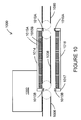
- FIG. 10 depicts a schematic diagram of a sorting system 1000 according to the disclosure.
- FIG. 10 presents a cut-away view of the sorting system 1000 generally as indicated by the line 10 - 10 in FIG. 9 .
- the system 1000 includes transport belts 1006 , 1008 and 1080 positioned end-to-end and operable to move a parcel 1002 or other item from one transport belt to another.
- a drive belt 1010 A is positioned at a first end of the transport belt 1008 and a drive belt 1010 B is positioned at an opposite end of the drive belt 1008 .
- a sweeper 1014 is mechanically coupled at a first end to an upper portion of the drive belt 1010 A and at a second end to an upper portion of the drive belt 1010 B.
- a sweeper 1016 is mechanically coupled to a lower portion of the drive belts 1010 A and 1010 B.
- the sweepers 1014 and 1016 are coupled to the drive belts 1010 A and 1010 B at both ends by gussets 1017 .
- the upper portions of the drive belts 1010 A and 1010 B are oriented substantially parallel to an upper surface of the transport belt 1008 .
- the upper portions of the drive belts 1010 A and 1010 B are positioned below the upper surface of the transport belt 1008 , so as not to obstruct a parcel as it moves onto or off of the transport belt 1008 .
- the sweeper 1014 includes a bar 1015 A, to which is mounted a brush 1015 B.
- the bar 1015 A and the brush 1015 B are positioned above the upper surface of the transport belt 1008 .
- the brush 1015 B extends from the bar toward the upper surface of the transport belt 1008 .
- the brush 1015 B may contact the transport belt 1008 as the sweeper 1014 moves through its sorting motion without causing significant wear to the transport belt 908 . Additionally, the brush 1015 B reduces the likelihood that an object will become wedged between the bar 1015 A and the transport belt 908 , preventing motion of the sweeper 1014 or damaging the transport belt 908 .
- a plastic or rubber flap or other flexible structure may be used instead of the brush 1015 B.
- a stiff structure may be used instead of the brush 1015 B and the sweeper 1014 configured so that a lower edge of the stiff structure is positioned adjacent to, but not in contact with, the transport belt 908 .
- machine usable/readable or computer usable/readable mediums include: nonvolatile, hard-coded type mediums such as read only memories (ROMs) or erasable, electrically programmable read only memories (EEPROMs), and user-recordable type mediums such as floppy disks, hard disk drives and compact disk read only memories (CD-ROMs) or digital versatile disks (DVDs).
- ROMs read only memories
- EEPROMs electrically programmable read only memories
- user-recordable type mediums such as floppy disks, hard disk drives and compact disk read only memories (CD-ROMs) or digital versatile disks (DVDs).
- computer readable mediums can include transitory and non-transitory mediums, unless otherwise limited in the claims appended hereto.
Landscapes
- Engineering & Computer Science (AREA)
- Mechanical Engineering (AREA)
- Discharge Of Articles From Conveyors (AREA)
Abstract
Description
Claims (20)
Priority Applications (1)
| Application Number | Priority Date | Filing Date | Title |
|---|---|---|---|
| US13/042,634 US8413787B2 (en) | 2010-03-10 | 2011-03-08 | Sweeper sorting apparatus and method |
Applications Claiming Priority (2)
| Application Number | Priority Date | Filing Date | Title |
|---|---|---|---|
| US31227210P | 2010-03-10 | 2010-03-10 | |
| US13/042,634 US8413787B2 (en) | 2010-03-10 | 2011-03-08 | Sweeper sorting apparatus and method |
Publications (2)
| Publication Number | Publication Date |
|---|---|
| US20110220459A1 US20110220459A1 (en) | 2011-09-15 |
| US8413787B2 true US8413787B2 (en) | 2013-04-09 |
Family
ID=44558899
Family Applications (1)
| Application Number | Title | Priority Date | Filing Date |
|---|---|---|---|
| US13/042,634 Expired - Fee Related US8413787B2 (en) | 2010-03-10 | 2011-03-08 | Sweeper sorting apparatus and method |
Country Status (1)
| Country | Link |
|---|---|
| US (1) | US8413787B2 (en) |
Cited By (5)
| Publication number | Priority date | Publication date | Assignee | Title |
|---|---|---|---|---|
| US9511949B2 (en) * | 2014-08-25 | 2016-12-06 | Kabushiki Kaisha Toshiba | Article sorting apparatus |
| US20190233223A1 (en) * | 2018-01-26 | 2019-08-01 | Optimus Sorter Holding B.V. | Sorting Device With Improved Capacity |
| US20210387814A1 (en) * | 2019-02-18 | 2021-12-16 | Eurosort B.V. | A cross-belt sorter |
| US11325788B2 (en) * | 2018-10-25 | 2022-05-10 | Suzhou Jinfeng Iot Technology Co., Ltd. | Double-loop cross-belt sorter, cross-belt sorter system and sorting method |
| EP4140605A4 (en) * | 2020-04-23 | 2024-05-22 | Beijing Jingdong Qianshi Technology Co., Ltd. | Sorting vehicle, goods sorting system, and goods sorting method |
Families Citing this family (1)
| Publication number | Priority date | Publication date | Assignee | Title |
|---|---|---|---|---|
| CN110479618B (en) * | 2019-09-27 | 2024-08-23 | 河北工程大学 | Logistics sorting detection device and sorting method thereof |
Citations (15)
| Publication number | Priority date | Publication date | Assignee | Title |
|---|---|---|---|---|
| US3469887A (en) * | 1966-04-30 | 1969-09-30 | Tsubakimoto Chain Co | Apparatus for branching off floating articles |
| US3680692A (en) * | 1970-12-10 | 1972-08-01 | Us Plywood Champ Papers Inc | Board transfer device |
| US4318484A (en) * | 1979-05-08 | 1982-03-09 | Datasaab Ab | Device for sorting out individual articles which differ from the main quantity in a consecutive feedout |
| US4541520A (en) * | 1983-09-26 | 1985-09-17 | Great Plains Ventures | Right angle transfer conveyor system and a method for transferring articles at a right angle |
| US5000657A (en) * | 1989-01-23 | 1991-03-19 | Gunther International, Ltd. | Two-way conveyor |
| US5609236A (en) * | 1995-03-21 | 1997-03-11 | P.E.E.M. Forderanlagen Gesellschaft m.b.H. | Roller conveying device |
| US5743375A (en) * | 1995-09-11 | 1998-04-28 | Industrial Technology Research Institute | Conveyer transfer apparatus |
| US5899453A (en) * | 1996-10-21 | 1999-05-04 | Bell & Howell Mail Processing Systems | Document collector, diverter and stager apparatus and method |
| US6264042B1 (en) * | 1999-11-15 | 2001-07-24 | United Parcel Service Of America, Inc. | Bilateral sorter |
| US20020046921A1 (en) * | 2000-08-24 | 2002-04-25 | Macswan John | Article transferring device |
| US20030075416A1 (en) * | 2001-08-24 | 2003-04-24 | Prutu Victor Nicholas | Method and apparatus for measuring and diverting an object from a high-speed conveyor |
| US6644459B2 (en) * | 2001-12-19 | 2003-11-11 | Rapistan Systems Advertising Corp. | Belt transfer assembly |
| US20040226803A1 (en) * | 2003-04-04 | 2004-11-18 | Siemens Aktiengesellschaft | Transport system for containers, and corner transfer unit for such a transport system |
| US6974019B2 (en) * | 2002-11-19 | 2005-12-13 | Laitram, L.L.C. | Conveyor with a motorized transport element |
| US6978995B2 (en) * | 2001-08-29 | 2005-12-27 | Bowe Bell +Howell Company | Apparatus and method for collecting flat and letter units |
-
2011
- 2011-03-08 US US13/042,634 patent/US8413787B2/en not_active Expired - Fee Related
Patent Citations (16)
| Publication number | Priority date | Publication date | Assignee | Title |
|---|---|---|---|---|
| US3469887A (en) * | 1966-04-30 | 1969-09-30 | Tsubakimoto Chain Co | Apparatus for branching off floating articles |
| US3680692A (en) * | 1970-12-10 | 1972-08-01 | Us Plywood Champ Papers Inc | Board transfer device |
| US4318484A (en) * | 1979-05-08 | 1982-03-09 | Datasaab Ab | Device for sorting out individual articles which differ from the main quantity in a consecutive feedout |
| US4541520A (en) * | 1983-09-26 | 1985-09-17 | Great Plains Ventures | Right angle transfer conveyor system and a method for transferring articles at a right angle |
| US5000657A (en) * | 1989-01-23 | 1991-03-19 | Gunther International, Ltd. | Two-way conveyor |
| US5609236A (en) * | 1995-03-21 | 1997-03-11 | P.E.E.M. Forderanlagen Gesellschaft m.b.H. | Roller conveying device |
| US5743375A (en) * | 1995-09-11 | 1998-04-28 | Industrial Technology Research Institute | Conveyer transfer apparatus |
| US5901953A (en) * | 1996-10-21 | 1999-05-11 | Bell & Howell Mail Processing Systems Company | Diverter apparatus and method for sheets or envelopes |
| US5899453A (en) * | 1996-10-21 | 1999-05-04 | Bell & Howell Mail Processing Systems | Document collector, diverter and stager apparatus and method |
| US6264042B1 (en) * | 1999-11-15 | 2001-07-24 | United Parcel Service Of America, Inc. | Bilateral sorter |
| US20020046921A1 (en) * | 2000-08-24 | 2002-04-25 | Macswan John | Article transferring device |
| US20030075416A1 (en) * | 2001-08-24 | 2003-04-24 | Prutu Victor Nicholas | Method and apparatus for measuring and diverting an object from a high-speed conveyor |
| US6978995B2 (en) * | 2001-08-29 | 2005-12-27 | Bowe Bell +Howell Company | Apparatus and method for collecting flat and letter units |
| US6644459B2 (en) * | 2001-12-19 | 2003-11-11 | Rapistan Systems Advertising Corp. | Belt transfer assembly |
| US6974019B2 (en) * | 2002-11-19 | 2005-12-13 | Laitram, L.L.C. | Conveyor with a motorized transport element |
| US20040226803A1 (en) * | 2003-04-04 | 2004-11-18 | Siemens Aktiengesellschaft | Transport system for containers, and corner transfer unit for such a transport system |
Cited By (8)
| Publication number | Priority date | Publication date | Assignee | Title |
|---|---|---|---|---|
| US9511949B2 (en) * | 2014-08-25 | 2016-12-06 | Kabushiki Kaisha Toshiba | Article sorting apparatus |
| US20190233223A1 (en) * | 2018-01-26 | 2019-08-01 | Optimus Sorter Holding B.V. | Sorting Device With Improved Capacity |
| US10577194B2 (en) * | 2018-01-26 | 2020-03-03 | Optimus Sorter Holding B.V. | Sorting device with improved capacity |
| US11325788B2 (en) * | 2018-10-25 | 2022-05-10 | Suzhou Jinfeng Iot Technology Co., Ltd. | Double-loop cross-belt sorter, cross-belt sorter system and sorting method |
| US20210387814A1 (en) * | 2019-02-18 | 2021-12-16 | Eurosort B.V. | A cross-belt sorter |
| US12110191B2 (en) * | 2019-02-18 | 2024-10-08 | Eurosort B.V. | Cross-belt sorter |
| EP4140605A4 (en) * | 2020-04-23 | 2024-05-22 | Beijing Jingdong Qianshi Technology Co., Ltd. | Sorting vehicle, goods sorting system, and goods sorting method |
| US12097535B2 (en) | 2020-04-23 | 2024-09-24 | Beijing Jingdong Qianshi Technology Co., Ltd. | Sorting vehicle, goods sorting system, and goods sorting method |
Also Published As
| Publication number | Publication date |
|---|---|
| US20110220459A1 (en) | 2011-09-15 |
Similar Documents
| Publication | Publication Date | Title |
|---|---|---|
| US8413787B2 (en) | Sweeper sorting apparatus and method | |
| US12128572B2 (en) | Robotic sortation system | |
| JP7631443B2 (en) | Material handling device having transport vehicle | |
| US6015039A (en) | High speed tilted belt sorter | |
| US11407595B2 (en) | Methods and apparatuses for performing article singulation | |
| US9364865B2 (en) | System and method for sorting parcel | |
| KR102054864B1 (en) | Rotary Typed Sweeping Sorter And Conveyor System Using The Same | |
| EP3383745B1 (en) | Systems and methods of auto sacking of parcels | |
| US10815069B1 (en) | Parcel singulation systems and methods | |
| MX2007012773A (en) | Parcel labeling, conveying, and sorting method and apparatus. | |
| US10556253B2 (en) | Parcel sorting apparatus with routing manifold and diverter system | |
| US20060177291A1 (en) | Identification system for identifying objects | |
| US20180079606A1 (en) | Cascade de-layering | |
| US20210061578A1 (en) | Parcel processing systems and methods using selective parcel rotation | |
| US12012291B2 (en) | Parcel singulation systems and methods | |
| JP2017176942A (en) | Sorting device | |
| US9994400B2 (en) | Conveyors for sorting products | |
| US20240101355A1 (en) | Cross-belt sorter system | |
| US20230118229A1 (en) | Parcel merging and alignment using diverting shoes | |
| JP7208418B2 (en) | Sorting device and sorting method | |
| CN219092798U (en) | A express parcel sorting line | |
| KR102853804B1 (en) | Apparatus For Conveying Products Having Diverting Portion | |
| JP7740677B2 (en) | Inspection equipment and inspection system | |
| CN112070434B (en) | Logistics query platform based on big data | |
| JPH10156289A (en) | Mail sorting apparatus and method |
Legal Events
| Date | Code | Title | Description |
|---|---|---|---|
| AS | Assignment |
Owner name: SIEMENS INDUSTRY, INC., GEORGIA Free format text: ASSIGNMENT OF ASSIGNORS INTEREST;ASSIGNORS:BROUWER, DAVID J.;GIEGLING, JEFFREY R.;REEL/FRAME:025916/0757 Effective date: 20110307 |
|
| STCF | Information on status: patent grant |
Free format text: PATENTED CASE |
|
| FPAY | Fee payment |
Year of fee payment: 4 |
|
| AS | Assignment |
Owner name: SIEMENS POSTAL, PARCEL & AIRPORT LOGISTICS LLC, TE Free format text: ASSIGNMENT OF ASSIGNORS INTEREST;ASSIGNOR:SIEMENS INDUSTRY, INC.;REEL/FRAME:049081/0626 Effective date: 20190430 |
|
| AS | Assignment |
Owner name: SIEMENS LOGISTICS LLC, UNITED STATES Free format text: CHANGE OF NAME;ASSIGNOR:SIEMENS POSTAL, PARCEL & AIRPORT LOGISTICS LLC;REEL/FRAME:051588/0282 Effective date: 20190516 |
|
| MAFP | Maintenance fee payment |
Free format text: PAYMENT OF MAINTENANCE FEE, 8TH YEAR, LARGE ENTITY (ORIGINAL EVENT CODE: M1552); ENTITY STATUS OF PATENT OWNER: LARGE ENTITY Year of fee payment: 8 |
|
| AS | Assignment |
Owner name: KOERBER SUPPLY CHAIN LLC, TEXAS Free format text: ASSIGNMENT OF ASSIGNORS INTEREST;ASSIGNOR:SIEMENS LOGISTICS LLC;REEL/FRAME:061509/0808 Effective date: 20220830 |
|
| FEPP | Fee payment procedure |
Free format text: MAINTENANCE FEE REMINDER MAILED (ORIGINAL EVENT CODE: REM.); ENTITY STATUS OF PATENT OWNER: LARGE ENTITY |
|
| LAPS | Lapse for failure to pay maintenance fees |
Free format text: PATENT EXPIRED FOR FAILURE TO PAY MAINTENANCE FEES (ORIGINAL EVENT CODE: EXP.); ENTITY STATUS OF PATENT OWNER: LARGE ENTITY |
|
| STCH | Information on status: patent discontinuation |
Free format text: PATENT EXPIRED DUE TO NONPAYMENT OF MAINTENANCE FEES UNDER 37 CFR 1.362 |
|
| FP | Lapsed due to failure to pay maintenance fee |
Effective date: 20250409 |