US8413678B2 - Mechatronic device - Google Patents
Mechatronic device Download PDFInfo
- Publication number
- US8413678B2 US8413678B2 US11/666,057 US66605705A US8413678B2 US 8413678 B2 US8413678 B2 US 8413678B2 US 66605705 A US66605705 A US 66605705A US 8413678 B2 US8413678 B2 US 8413678B2
- Authority
- US
- United States
- Prior art keywords
- pressure
- mechatronic device
- sensors
- mechatronic
- housing
- Prior art date
- Legal status (The legal status is an assumption and is not a legal conclusion. Google has not performed a legal analysis and makes no representation as to the accuracy of the status listed.)
- Active, expires
Links
Images


Classifications
-
- F—MECHANICAL ENGINEERING; LIGHTING; HEATING; WEAPONS; BLASTING
- F16—ENGINEERING ELEMENTS AND UNITS; GENERAL MEASURES FOR PRODUCING AND MAINTAINING EFFECTIVE FUNCTIONING OF MACHINES OR INSTALLATIONS; THERMAL INSULATION IN GENERAL
- F16H—GEARING
- F16H61/00—Control functions within control units of change-speed- or reversing-gearings for conveying rotary motion ; Control of exclusively fluid gearing, friction gearing, gearings with endless flexible members or other particular types of gearing
- F16H61/0003—Arrangement or mounting of elements of the control apparatus, e.g. valve assemblies or snapfittings of valves; Arrangements of the control unit on or in the transmission gearbox
- F16H61/0006—Electronic control units for transmission control, e.g. connectors, casings or circuit boards
-
- F—MECHANICAL ENGINEERING; LIGHTING; HEATING; WEAPONS; BLASTING
- F15—FLUID-PRESSURE ACTUATORS; HYDRAULICS OR PNEUMATICS IN GENERAL
- F15B—SYSTEMS ACTING BY MEANS OF FLUIDS IN GENERAL; FLUID-PRESSURE ACTUATORS, e.g. SERVOMOTORS; DETAILS OF FLUID-PRESSURE SYSTEMS, NOT OTHERWISE PROVIDED FOR
- F15B21/00—Common features of fluid actuator systems; Fluid-pressure actuator systems or details thereof, not covered by any other group of this subclass
- F15B21/08—Servomotor systems incorporating electrically operated control means
-
- Y—GENERAL TAGGING OF NEW TECHNOLOGICAL DEVELOPMENTS; GENERAL TAGGING OF CROSS-SECTIONAL TECHNOLOGIES SPANNING OVER SEVERAL SECTIONS OF THE IPC; TECHNICAL SUBJECTS COVERED BY FORMER USPC CROSS-REFERENCE ART COLLECTIONS [XRACs] AND DIGESTS
- Y10—TECHNICAL SUBJECTS COVERED BY FORMER USPC
- Y10T—TECHNICAL SUBJECTS COVERED BY FORMER US CLASSIFICATION
- Y10T137/00—Fluid handling
- Y10T137/7722—Line condition change responsive valves
- Y10T137/7758—Pilot or servo controlled
- Y10T137/7761—Electrically actuated valve
-
- Y—GENERAL TAGGING OF NEW TECHNOLOGICAL DEVELOPMENTS; GENERAL TAGGING OF CROSS-SECTIONAL TECHNOLOGIES SPANNING OVER SEVERAL SECTIONS OF THE IPC; TECHNICAL SUBJECTS COVERED BY FORMER USPC CROSS-REFERENCE ART COLLECTIONS [XRACs] AND DIGESTS
- Y10—TECHNICAL SUBJECTS COVERED BY FORMER USPC
- Y10T—TECHNICAL SUBJECTS COVERED BY FORMER US CLASSIFICATION
- Y10T137/00—Fluid handling
- Y10T137/8158—With indicator, register, recorder, alarm or inspection means
- Y10T137/8326—Fluid pressure responsive indicator, recorder or alarm
Definitions
- the present invention relates to an improved mechatronic device.
- EP 1 180 602 A1 describes a control-valve device with an electronics box that contains a printed circuit board for mounting electronic components and permits connection to an external bus.
- One or more solenoid valves can be plugged into the electronics box and thus brought into electrical contact. Electrical control signals arriving from the bus are processed by the electronic unit and distributed to the associated valves.
- the control-valve device described in EP 1 180 602 A1 does not have any sensors.
- DE 100 49 958 A1 describes a fluidic arrangement as well as a valve array and actuator therefor.
- the associated actuator is provided with a working cylinder with a piston, the position of which can be detected via displacement sensors or limit switches.
- the output signals of the sensors can be transmitted optionally by hard-wired or wireless means. In the case of wireless communication, the sensors are configured as transponders.
- the interface to the pneumatic or hydraulic pressure duct can become prone to leaks.
- a mechatronic device especially if it is installed in a motor vehicle, is often exposed to electrical interference due to ambient radio waves. This can adversely affect signal transmission.
- transponder technology the use of transponder technology is increasing and, as a result, it can be expected that the cost of the needed modules—transmitter and receiver—will fall).
- DE 199 24 830 A1 describes a method of utilizing transponder technology to measure the tire pressure of a vehicle tire without contact with the body. A battery to supply power to the sensor located in the tire is not necessary for this purpose. Transmission can take place when a request signal (oscillation) is sent externally, thus exciting a pressure-dependent oscillation circuit in the sensor, which then rapidly returns a corresponding pressure-dependent analog signal.
- BLUETOOTH® technology Another known method involves BLUETOOTH® technology.
- the article titled “Bluetooth-frequency energy carriers,” Auto & Elektronik January 2002 describes the use of BLUETOOTHTM technology to monitor tire-pressure, wherein both the pressure signals and the energy to supply the pressure sensor are transmitted wirelessly by radio waves.
- an improved mechatronic device is provided that overcomes disadvantages associated with conventional devices.
- a mechatronic device in accordance with the present invention, includes a housing encompassing a mechanical part and an electronic part.
- the mechanical part includes one or more solenoid valves and pressure-conveying ducts;
- the electronic part includes a printed circuit board with electronic components.
- sensor modules for measuring physical parameters are disposed directly inside the pressure-conveying ducts or in cavities in communication therewith without a special seal and without electrical terminals.
- Wireless communication over short distances is effected inside the mechatronic housing using radio techniques or light-emitting elements, e.g., light emitting diodes (“LEDs”), increasing operating reliability.
- LEDs light emitting diodes
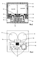
- FIG. 1 depicts a mechatronic device with a solenoid valve, an electronic control unit and a sensor module installed in a pressure-conveying duct in accordance with the present invention
- FIG. 2 is a sectional view of the embodiment of the mechatronic device depicted in FIG. 1 at the level of the electronic printed circuit board;
- FIG. 3 is a sectional view of the embodiment of the mechatronic device depicted in FIG. 1 showing inlet and outlet valves as well as pressure ports;
- FIG. 4 is a sectional view of the embodiment of the mechatronic device depicted in FIG. 1 showing inlet and outlet valves as well as an electronic control unit;
- FIG. 5 is a schematic diagram illustrating energy and data transmission between the electronic control unit and the sensor module of an embodiment of the mechatronic device according to the present invention
- FIG. 6 is a sectional view of an electronic unit with two reading stations in combination with two sensor modules in accordance with an embodiment of the inventive mechatronic device
- FIG. 7 is a sectional view of an electronic unit with one common reading station in combination with two sensor modules in accordance with an embodiment of the inventive mechatronic device
- FIG. 8 is a sectional view of an electronic unit with one reading station and a sensor module located only partly in the pressure-conveying duct in accordance with an embodiment of the inventive mechatronic device;
- FIG. 9 is a sectional view of a pressure-conveying duct with one sensor module clamped in place in accordance with an embodiment of the inventive mechatronic device
- FIG. 10 is a sectional view of a pressure-conveying duct with one sensor module bonded in place in accordance with an embodiment of the inventive mechatronic device
- FIG. 11 is a sectional view of two pressure-conveying ducts with two sensor modules screwed into place in accordance with an embodiment of the inventive mechatronic device
- FIG. 12 depicts a mechatronic device with a solenoid valve, an electronic control unit and a sensor module installed in a pressure-conveying duct in accordance with an embodiment of the present invention
- FIG. 13 is a sectional view of the mechatronic device depicted in FIG. 12 at the level of the electronic printed circuit board;
- FIG. 14 is a sectional view of the mechatronic device depicted in FIG. 12 showing inlet and outlet valves as well as pressure ports;
- FIG. 15 is a sectional view of the mechatronic device depicted in FIG. 12 showing inlet and outlet valves as well as an electronic control unit;
- FIG. 16 a is a schematic diagram illustrating energy and data transmission between the electronic control unit and a pressure sensor module of an embodiment of the mechatronic device according to the present invention
- FIG. 16 b is a schematic diagram illustrating energy and data transmission between the electronic control unit and two pressure sensor modules with two reading stations of an embodiment of the mechatronic device according to the present invention
- FIG. 16 c is a schematic diagram illustrating energy and data transmission between the electronic control unit and two pressure sensor modules with one common reading station of an embodiment of the mechatronic device according to the present invention
- FIG. 17 is a sectional view of an electronic unit with two reading stations in combination with two sensor modules in accordance with an embodiment of the inventive mechatronic device
- FIG. 18 is a sectional view of an electronic unit with two reading stations in combination with two sensor modules in accordance with an embodiment of the inventive mechatronic device
- FIG. 19 is a sectional view of an electronic unit with one reading station and a sensor module located only partly in the pressure-conveying duct in accordance with an embodiment of the inventive mechatronic device;
- FIG. 20 is a sectional view of a pressure-conveying duct with one sensor module clamped in place in accordance with an embodiment of the inventive mechatronic device
- FIG. 21 is a sectional view of a pressure-conveying duct with one sensor module bonded in place in accordance with an embodiment of the inventive mechatronic device.
- FIG. 22 is a sectional view through two pressure-conveying ducts with two sensor modules screwed into place in accordance with an embodiment of the inventive mechatronic device.
- FIG. 1 depicts a mechatronic unit according to an embodiment of the present invention, in this case for operation of a valve array, with a housing ( 1 ) having a lower part ( 21 ) and a cover ( 20 ).
- the mechatronic device further comprises a mechanical part ( 2 ) and an electronic part ( 3 ).
- Electronic part ( 3 ) can be disposed inside common cover ( 20 ). However, it can also be disposed in a separate electronics housing ( 26 ) (see FIG. 6 ), which is mounted on mechanical part ( 2 ).
- a solenoid valve pair ( 5 , 6 ) (see FIG. 3 ) including an inlet valve ( 5 ) and an outlet valve ( 6 ). Only the inlet valve ( 5 ) is depicted in FIG. 1 .
- a valve-closing element ( 31 ) is provided that can close a valve seat ( 27 ) by means of a seal ( 32 ). As a result, a passage for compressed air or a fluid can be opened and closed.
- At least one pressure port ( 16 ) is provided, which is disposed in lower part ( 21 ) of housing ( 1 ).
- a pressure-conveying duct ( 7 ) is provided to connect pressure port ( 16 ) to valve seat ( 27 ).
- the valve array with associated pressure-conveying ducts can be used to raise, lower or hold a pressure in a vessel, for example.
- Pressure-conveying ducts ( 7 , 8 , 9 ) can have different cross-sectional shapes, for example, round or rectangular cross sections.
- a sensor module ( 13 ) is disposed in pressure-conveying duct ( 9 ) (or it can be disposed in a cavity in communication therewith).
- Sensor module ( 13 ) includes a pressure sensor ( 29 ) and a transponder ( 30 ) (see FIG. 5 ).
- Sensor module ( 13 ) is fixed by suitable means inside pressure-conveying duct ( 9 ).
- Sensor module ( 13 ) can be held in place by a clamping force (see FIG. 9 ), for example.
- a clamping force see FIG. 9
- it is equipped with springs ( 35 , 36 ) which are braced against the inside wall of the pressure-conveying duct in which it is disposed, which can be flat or round.
- Sensor module ( 13 ) can also be fixed to the walls of any of pressure-conveying ducts ( 7 , 8 , 9 ) by means of a bonding agent ( 37 ) (see FIG. 10 ).
- the sensor module ( 40 in FIG. 11 ) can also be provided with a cylindrical housing having an external thread ( 41 ), with which it can be screwed into a blind hole ( 38 ) extending from a pressure-conveying duct ( 7 , 8 , 9 ) (see FIG. 11 , right).
- Pressure-conveying duct ( 9 ) in FIG. 1 is formed in part by an intermediate plate ( 19 ), which is preferably made of a nonmetallic material, such as a plastic.
- mechanical part ( 2 ) comprising lower part ( 21 ) with pressure-conveying duct ( 7 ) as well as pressure port ( 16 ), is preferably made of metal, such as aluminum, as is also the case with cover ( 20 ).
- Pressure-conveying ducts can have any desired form. They can be configured as bores, cavities or even blind bores, into which there is screwed a sensor.
- Electronic part ( 3 ) of housing ( 1 ) includes an electronic printed circuit board ( 10 ), which is equipped with electronic components ( 11 ).
- Electronic printed circuit board ( 10 ) includes a reading station ( 12 ), which according to an embodiment of the invention communicates with sensor module ( 13 ) by means of radio technology. Wireless transmission of energy or electrical data in both directions is made possible by constructing intermediate plate ( 19 ) of plastic.
- electronic printed circuit board ( 10 ) is connected by a connecting cable ( 18 ) to an electrical plug connector ( 17 ).
- FIG. 2 is a sectional view through the embodiment of mechatronic housing ( 1 ) depicted in FIG. 1 at the level of electronic printed circuit board ( 10 ).
- Electronic components ( 11 ), including a microprocessor ( 28 ) and reading station ( 12 ), are disposed on electronic printed circuit board ( 10 ).
- the reading station communicates by radio technology with two sensor modules ( 13 , 14 ). These are disposed in pressure-conveying ducts ( 9 ), which can be shaped differently depending on need.
- Pressure-conveying ducts ( 9 ) are disposed completely or partly in intermediate plate ( 19 ), which is made of insulating material (see FIG. 1 ).
- FIG. 3 is another sectional view through the embodiment of mechatronic housing ( 1 ) depicted in FIG. 1 showing solenoid valves ( 5 , 6 ), which operate as the inlet and outlet valves. Also depicted are sensor modules ( 13 , 14 ), which in this case are disposed in the space between intermediate plate ( 19 ) and lower part ( 21 ) of mechatronic housing ( 1 ). Pressure ports ( 15 , 16 ) for connecting the mechatronic device to a compressed-air system or to a hydraulic system are also depicted.
- FIG. 4 is a further sectional view through the mechatronic device at the level of electronic printed circuit board ( 10 ). Solenoid valves ( 5 , 6 ) and the assembled electronic printed circuit board ( 10 ) with electronic components ( 11 ), sensor modules ( 13 , 14 ) and common reading station ( 12 ) are depicted.
- FIG. 5 is a schematic diagram depicting energy and data transmission between the electronic control unit or system electronics disposed on electronic printed circuit board ( 10 ) and sensor module ( 13 ).
- Electronic printed circuit board ( 10 ) includes, among other components not shown, reading station ( 12 ) and microprocessor ( 28 ). Magnet windings ( 24 , 25 ) of solenoid valves ( 5 , 6 ) are further connected to printed circuit board ( 10 ). An antenna ( 22 ), which can be, for example, a coil printed on printed circuit board ( 10 ), is connected to reading station ( 12 ).
- a transponder ( 30 ) is disposed on sensor module ( 13 ).
- Transponder ( 30 ) is also connected to an antenna ( 23 ), which can also take the form of a coil printed on the printed circuit board.
- Transponder ( 30 ) is further connected to a line that transmits energy to and another line that receives data back from pressure sensor ( 29 ).
- an ambient pressure (P) can be converted into a voltage (U), which is proportional to the pressure, and communicated to transponder ( 30 ).
- a transmission pulse is sent from reading station ( 12 ) to sensor module ( 13 ), followed by return transmission of data, in this case pressure values (as depicted by arrows between electronic printed circuit board ( 10 ) and sensor module ( 13 ) in FIG. 5 ). It should be understood that, depending on design, energy transmission and data transmission can also take place simultaneously.
- a coded signal for identification of the responding sensor module ( 13 ) can also be transmitted back in addition to the return transmission of data.
- the transmission pulse can also be coded, for example, by using different frequencies to excite the different sensor modules from which a measured value is needed.
- pressure sensor ( 29 ) can also be part of transponder ( 30 ).
- the resonant frequency of the return response thus depends on the ambient pressure. In this case, there is no need for the illustrated separate transmission of energy and signal within sensor module ( 13 ).
- FIG. 6 shows an embodiment according to the present invention whereby electronic printed circuit board ( 10 ) is mounted in a separate electronics housing ( 26 ).
- Two reading stations ( 12 , 12 a ) are disposed on printed circuit board ( 10 ) and communicate via antennas ( 22 , 22 a ) with sensor modules ( 13 , 14 ).
- Sensor modules ( 13 , 14 ) are disposed directly in pressure-conveying ducts ( 9 ), which, in this case, are tubular. An adequate cross section for flow of pressurized fluid should be provided.
- FIG. 7 shows an embodiment of electronic printed circuit board ( 10 ) that is mounted in an electronics housing ( 26 ) but, in this case, is equipped with only a single, common reading station ( 12 ).
- Common reading station ( 12 ) communicates via a single antenna ( 22 ) with two sensor modules ( 13 , 14 ).
- FIG. 8 shows a further embodiment of the present invention, in which sensor module ( 13 ) is disposed only partly in pressure-conveying duct ( 9 ).
- a sensing part ( 33 ) of the sensor module extends into pressure-conveying duct ( 9 )
- a transmitting or receiving part ( 34 ) is disposed inside electronics housing ( 26 ), proximate reading station ( 12 ) with antenna ( 22 ).
- This embodiment has the advantage that intermediate plate ( 19 ) does not have to be made of insulating material. However, more space is required in electronics housing ( 26 ). Moreover, the possible arrangements of pressure-conveying ducts ( 9 ), which in this case are disposed underneath electronics housing ( 26 ), are more limited. Furthermore, this embodiment calls for adequate sealing of the interface between sensor module ( 13 ) and intermediate plate ( 19 ).
- reading stations ( 12 , 12 a ) and sensor modules ( 13 , 14 ) are disposed in close proximity to one another.
- This has the advantage that the transmitting powers of reading stations ( 12 , 12 a ) and of antennas ( 22 , 22 a , 23 ) can be low by design.
- “close proximity” is intended to mean a distance of approximately 1 to 5 cm, depending on the size of the mechatronic device.
- sensor modules can also sense and transmit other physical variables. Examples include temperatures, mass flow rates (such as mass flows of compressed air or fluids), displacements (such as displacements of valve elements), magnetic field strengths (such as field strengths of the magnet windings of the solenoid valves) and the chemical composition of the gas or fluid flowing in the pressure-conveying ducts.
- the wireless radio technology used in embodiments of the present invention can be transponder technology or BLUETOOTH® technology. Both technologies have been around for some time and are standardized, and therefore are to be regarded as adequately reliable and cost-effective.
- FIG. 12 depicts one such embodiment of an inventive mechatronic device utilizing data transmission by means of light, in this case for operation of a valve array, with a housing ( 1 ) including a lower part ( 21 ) and a cover ( 20 ).
- the mechatronic device further includes a mechanical part ( 2 ) and an electronic part ( 3 ).
- Electronic part ( 3 ) can be disposed inside the common cover ( 20 ). However, it can also be disposed in a separate electronics housing ( 26 ) (see FIG. 6 ), which is mounted on the mechanical part ( 2 ).
- a solenoid valve pair ( 5 , 6 ) is disposed under cover ( 20 ) (see FIG. 14 ) and includes an inlet valve ( 5 ) and an outlet valve ( 6 ). Only inlet valve ( 5 ) is shown in FIG. 12 .
- a valve-closing element ( 31 ) is provided, which can close a valve seat ( 27 ) by means of a seal ( 32 ). As a result, a passage for compressed air or a fluid can be opened and closed.
- valves other than solenoid valves can be utilized, such as, for example, piezo valves.
- mechanical part ( 2 ) of the mechatronic device can include actuators and/or motors (not illustrated), which can be controlled by electronic part ( 3 ).
- At least one pressure port ( 16 ) is provided, which is disposed in lower part ( 21 ) of housing ( 1 ).
- a pressure-conveying duct ( 7 ) is provided to connect pressure port ( 16 ) to valve seat ( 27 ).
- the valve array with associated pressure-conveying ducts can be used to raise, lower or hold a pressure in a vessel.
- Pressure-conveying ducts ( 7 , 8 , 9 ) can have different cross-sectional shapes, for example, round or rectangular cross sections.
- sensor module ( 13 ) is disposed in pressure-conveying duct ( 9 ) (or it can be disposed in a cavity in communication therewith).
- Module ( 13 ) includes pressure sensor ( 29 ), a signal-conditioning circuit ( 30 ), light-emitting element ( 45 ), an energy-receiving coil ( 23 ) and a rectifier ( 50 ) (see FIG. 16 a ).
- Sensor module ( 13 ) is fixed by suitable means inside pressure-conveying duct ( 9 ).
- Sensor module ( 13 ), together with light-emitting element ( 45 ), can be held in place by a clamping force (see FIG. 20 ), for example.
- a clamping force see FIG. 20
- it is equipped with springs ( 35 , 36 ), which are braced against the inside walls of the pressure-conveying duct in which it is disposed, which can be flat or round. Outward passage of light is permitted via a transparent intermediate plate ( 19 ).
- Sensor module ( 13 ) can also be fixed to the walls of any of pressure-conveying ducts ( 7 , 8 , 9 ) by means of a bonding agent ( 37 ) (see FIG. 21 ).
- a cylindrical sensor module ( 40 a ) can also be provided with a cylindrical housing having an external thread ( 41 ), with which it can be screwed into a blind hole ( 38 ) extending from a pressure-conveying duct ( 7 , 8 , 9 ) (see FIG. 22 , right).
- FIG. 22 further depicts two electronic printed circuit boards ( 10 , 10 a ), which are equipped with light-sensitive elements ( 44 , 44 a ).
- Light-sensitive elements ( 44 , 44 a ) receive data from two light-emitting elements ( 45 , 45 a ) of sensor modules ( 40 , 40 a ).
- Data transmission by (left) sensor module ( 40 ) takes place via an IR-transparent element ( 47 ), which can be screwed in pressure-tight manner into light-impermeable lower part ( 21 ).
- Data transmission by (right) sensor module ( 40 a ) takes place via an IR-transparent intermediate plate ( 19 ).
- Pressure-conveying duct ( 9 ) in FIG. 12 is formed in part by an intermediate plate ( 19 ), which is preferably made of a nonmetallic material, such as a plastic. At least part of intermediate plate ( 19 ) comprises IR-transparent material.
- mechanical part ( 2 ) comprising lower part ( 21 ) with pressure-conveying ducts ( 7 , 9 ) as well as pressure port ( 16 ), are preferably made of metal, such as aluminum, as is also the case with cover ( 20 ).
- pressure-conveying ducts ( 7 , 8 , 9 ) can have any desired form. They can be configured as bores, cavities of any desired form or even blind bores, into which there is screwed a sensor.
- electronic part ( 3 ) of housing ( 1 ) includes electronic printed circuit board (system electronics) ( 10 ), which is equipped with electronic components ( 11 ).
- Electronic printed circuit board ( 10 ) also includes light-sensitive element ( 44 ), which can receive data wirelessly by means of IR light from light-emitting element ( 45 ) mounted on sensor module ( 13 ) (see FIGS. 16 a to 16 c ).
- Electronic printed circuit board ( 10 ) further includes a transmitting coil ( 22 ) for supplying sensor module ( 13 ) with electrical energy.
- sensor module ( 13 ) includes a receiving coil ( 23 ) (see FIG. 16 a ).
- Wireless transmission of electrical data by means of IR light is achieved by constructing intermediate plate ( 19 ) at least partly of transparent plastic. Also, separate, light-guiding parts ( 47 ) can be inserted to penetrate through light-impermeable lower part ( 21 ) of the housing (see FIG. 22 ).
- electronic printed circuit board ( 10 ) is connected by connecting cable ( 18 ) to electrical plug connector ( 17 ).
- FIG. 13 is a sectional view through the embodiment of mechatronic housing ( 1 ) depicted in FIG. 12 at the level of electronic printed circuit board ( 10 ).
- Electronic components ( 11 ), including microprocessor ( 28 ) and two reading stations ( 12 , 12 a ), are disposed on electronic printed circuit board ( 10 ).
- the reading stations communicate wirelessly with two sensor modules ( 13 , 14 ).
- These are disposed in pressure-conveying ducts ( 9 ), which can be shaped differently depending on need.
- Pressure-conveying ducts ( 9 ) are disposed completely or partly in intermediate plate ( 19 ), which is made at least partly of transparent insulating material (see FIG. 12 ).
- the unit comprising light-sensitive element ( 44 , 44 a ) and amplifiers ( 48 , 48 a ) is designated as reading station ( 12 , 12 a ) (see FIG. 16 b ). In some cases, amplifiers ( 48 , 48 a ) may not even be necessary.
- FIG. 14 is another sectional view through the embodiment of mechatronic housing ( 1 ) depicted in FIG. 12 .
- Solenoid valves ( 5 , 6 ) operate as the inlet and the outlet valves.
- two sensor modules ( 13 , 14 ) which in this case are disposed between intermediate plate ( 19 ) and lower part ( 21 ) of mechatronic housing ( 1 ).
- Pressure ports ( 15 , 16 ) for connecting the mechatronic device to a compressed-air system or to a hydraulic system are also shown.
- FIG. 15 is a further sectional view through the mechatronic device at the level of electronic printed circuit board ( 10 ). Solenoid valves ( 5 , 6 ), the assembled printed circuit board ( 10 ) with electronic components ( 11 ), sensor modules ( 13 , 14 ) and neighboring common reading station ( 12 , 12 a ) associated therewith are shown. A common energy-transmitting coil ( 22 ) is also disposed on printed circuit board ( 10 ).
- FIGS. 16 a to 16 c illustrate energy and data transmission between the electronic control unit or system electronics disposed on electronic printed circuit board ( 10 ) and sensor modules ( 13 , 14 ).
- Electronic printed circuit board (system electronics) ( 10 ) in FIG. 16 a includes, among other elements not shown, reading station ( 12 ) with a light-sensitive element ( 44 ), in this embodiment a phototransistor, and microprocessor ( 28 ). Magnet windings ( 24 , 25 ) of solenoid valves ( 5 , 6 ) are further connected to printed circuit board ( 10 ).
- transmitting coil ( 22 ) which can be, for example, a coil printed on printed circuit board ( 10 ), is connected to an alternating current (“AC”) voltage generator ( 46 ).
- AC alternating current
- Pressure sensor ( 29 ) is disposed on associated sensor module ( 13 ) and can feed an output signal to a signal-conditioning circuit ( 30 ). To this there is connected, for data transmission to reading station ( 12 ), light-emitting element ( 45 ), in this case an IR LED.
- Receiving coil ( 23 ) is used to supply energy to pressure sensor ( 29 ).
- Receiving coil ( 23 ) can be configured as a coil printed on a printed circuit board, and can receive its energy inductively from transmitting coil ( 22 ).
- Rectifier ( 50 ) is connected to receiving coil ( 23 ).
- a capacitor or a battery (accumulator) (not illustrated) can be included in rectifier ( 50 ).
- a transmission pulse is sent from voltage generator ( 46 ) to sensor module ( 13 ), followed by return transmission of data, in this case pressure values, via light-emitting element ( 45 ) (as depicted by arrows between electronic printed circuit board ( 10 ) and sensor module ( 13 )).
- voltage generator ( 46 ) to sensor module ( 13 )
- return transmission of data in this case pressure values
- light-emitting element ( 45 ) as depicted by arrows between electronic printed circuit board ( 10 ) and sensor module ( 13 )
- signals are transmitted from two sensor modules ( 13 , 14 ) to electronic printed circuit board (system electronics) ( 10 ).
- the energy supply for both modules is provided via a common AC voltage generator ( 46 ) with common transmitting coil ( 22 ).
- Common energy transmission is preferable when the sensor modules to be supplied are not disposed too far away. Return transmission of data takes place separately for each sensor module, to two reading stations ( 12 , 12 a ), each with a light-sensitive element ( 44 , 44 a ).
- FIG. 17 depicts an embodiment of the present invention including two circuits of the same type as in FIG. 16 a .
- Electronic printed circuit board (system electronics) ( 10 ) in this case, is mounted in a separate electronics housing ( 26 ).
- the use of separate energy-transmitting coils is preferred when the modules to be supplied are disposed relatively far away from one another.
- Printed circuit board ( 10 ) further includes two light-sensitive elements ( 44 , 44 a ), which receive data from sensor modules ( 13 , 14 ).
- Sensor modules ( 13 , 14 ) are disposed directly in pressure-conveying ducts ( 9 ), which, in this embodiment, are tubular. An adequate cross section for flow of pressurized fluid should be provided.
- printed circuit board ( 10 ) is provided with perforations or bores in the region of light-sensitive elements ( 44 , 44 a ), and light-sensitive elements ( 44 , 44 a ) are inserted downward therethrough.
- Intermediate plate ( 19 ) is made of IR-transparent material.
- FIG. 18 corresponds to the circuit of FIG. 16 b .
- FIG. 17 it is a sectional view of an electronic printed circuit board ( 10 ) that is mounted in an electronics housing ( 26 ).
- the embodiment shown in FIG. 18 is equipped with only a single, common energy-transmitting coil ( 22 ). Via single transmitting coil ( 22 ), energy is supplied on demand or continuously to two sensor modules ( 13 , 14 ). If, temporarily, no sensor data are needed, the energy transmission can be stopped in order to save energy. Data transmission takes place via light-emitting elements ( 45 , 45 a ) to two light-sensitive elements ( 44 , 44 a ).
- FIG. 19 depicts a further embodiment of the present invention in which sensor module ( 13 ) is disposed only partly in pressure-conveying duct ( 9 ).
- sensing part ( 33 ) of sensor module ( 13 ) extends into pressure-conveying duct ( 9 )
- transmitting or receiving part ( 34 ) is disposed inside electronics housing ( 26 ) proximate reading station ( 12 ) with transmitting coil ( 22 ).
- Data transmission of the measured value takes place from light-emitting element ( 45 ) of sensor module ( 13 ) to light-sensitive element ( 44 ) connected to reading station ( 12 ).
- This embodiment has the advantage that intermediate plate ( 19 ) does not have to be made of IR-transparent insulating material. However, more space is needed in electronics housing ( 26 ). Moreover, the possible arrangements of pressure-conveying ducts ( 9 ), which in this case are disposed directly underneath electronics housing ( 26 ), are more limited. Furthermore, this embodiment calls for adequate pressure-tight sealing of the interface between sensor module ( 13 ) and intermediate plate ( 19 ).
- reading stations ( 12 , 12 a ) and sensor modules ( 13 , 14 ) are disposed in close proximity to one another (e.g., a distance of approximately 1 to 5 cm, depending on the size of the mechatronic device).
- This has the advantage that the transmitting powers of AC voltage generators ( 46 ) for energy transmission and of energy transmitting and receiving coils ( 22 , 23 ) can be low by design.
- sensor modules ( 13 , 14 ) can also sense and transmit other physical variables (e.g., temperatures, mass flow rates (such as mass flows of compressed air or fluids), displacements (such as displacements of valve elements), magnetic field strengths (such as field strengths of the magnet windings of the solenoid valves) and the chemical composition of the gas or fluid flowing in the pressure-conveying ducts).
- other physical variables e.g., temperatures, mass flow rates (such as mass flows of compressed air or fluids), displacements (such as displacements of valve elements), magnetic field strengths (such as field strengths of the magnet windings of the solenoid valves) and the chemical composition of the gas or fluid flowing in the pressure-conveying ducts).
- differential-pressure sensors can detect the pressure difference between a pressure-conveying duct ( 9 ) and the interior of an electronic housing ( 26 ), especially in the configuration according to the embodiment of the present invention depicted in FIG. 19 .
- pressure sensors mounted completely in pressure-conveying ducts are designed as absolute-value pressure sensors.
- IR LEDs are used as light-emitting elements. These LEDs have been around for some time and are standardized, and therefore are to be regarded as adequately reliable and cost-effective. Data transmission by means of IR LEDs is also known and proven to those of ordinary skill in the art, for example from remote control of television receivers.
- IR LEDs Compared with other LEDs that emit in the visible region, IR LEDs have the advantage that reliable data transmission is assured even if the inside faces of pressure-conveying ducts ( 9 ) are dirty.
- IR LEDs instead of IR LEDs, it is also possible to use laser diodes, especially when the transmission distance is relatively long.
- Other examples of light-sensitive elements that can be used are phototransistors and photodiodes.
Landscapes
- Engineering & Computer Science (AREA)
- General Engineering & Computer Science (AREA)
- Mechanical Engineering (AREA)
- Chemical & Material Sciences (AREA)
- Analytical Chemistry (AREA)
- Physics & Mathematics (AREA)
- Fluid Mechanics (AREA)
- Arrangements For Transmission Of Measured Signals (AREA)
- Measuring Fluid Pressure (AREA)
Abstract
Description
Claims (16)
Applications Claiming Priority (7)
| Application Number | Priority Date | Filing Date | Title |
|---|---|---|---|
| DE200410053200 DE102004053200A1 (en) | 2004-11-04 | 2004-11-04 | Mechatronic system has sensing modules for measuring of physical parameters built into one or more pressure-carrying channels and communicate cablelessly by radio technology with at least one reading station installed on plate |
| DE102004053200.1 | 2004-11-04 | ||
| DE102004053200 | 2004-11-04 | ||
| DE200510036663 DE102005036663B4 (en) | 2004-11-04 | 2005-08-04 | Mechatronics I |
| DE102005036663 | 2005-08-04 | ||
| DE102005036663.5 | 2005-08-04 | ||
| PCT/EP2005/011736 WO2006048269A1 (en) | 2004-11-04 | 2005-11-03 | Mechatronic device |
Publications (2)
| Publication Number | Publication Date |
|---|---|
| US20080115844A1 US20080115844A1 (en) | 2008-05-22 |
| US8413678B2 true US8413678B2 (en) | 2013-04-09 |
Family
ID=35457876
Family Applications (1)
| Application Number | Title | Priority Date | Filing Date |
|---|---|---|---|
| US11/666,057 Active 2028-06-06 US8413678B2 (en) | 2004-11-04 | 2005-11-03 | Mechatronic device |
Country Status (4)
| Country | Link |
|---|---|
| US (1) | US8413678B2 (en) |
| EP (1) | EP1809937B1 (en) |
| DE (1) | DE102005036663B4 (en) |
| WO (1) | WO2006048269A1 (en) |
Cited By (3)
| Publication number | Priority date | Publication date | Assignee | Title |
|---|---|---|---|---|
| US20150047720A1 (en) * | 2012-03-27 | 2015-02-19 | Brt Group Pty Ltd | Solenoid device with sensor |
| US20180106023A1 (en) * | 2015-03-04 | 2018-04-19 | Franke Water Systems Ag | Electronically controlled sanitary fitting |
| US11181206B2 (en) | 2017-12-22 | 2021-11-23 | Buerkert Werke Gmbh & Co. Kg | Valve module with wireless energy-transfer unit |
Families Citing this family (13)
| Publication number | Priority date | Publication date | Assignee | Title |
|---|---|---|---|---|
| DE102006038163A1 (en) * | 2006-08-16 | 2008-02-21 | Siemens Ag | Compression device and method for adjusting a compression pressure |
| DE102007015111B4 (en) * | 2007-03-29 | 2010-01-07 | Festo Ag & Co. Kg | Sensor device for a fluid power device |
| JP5051753B2 (en) * | 2007-05-21 | 2012-10-17 | 株式会社フジキン | Valve operation information recording system |
| DE102009045873A1 (en) | 2009-10-20 | 2011-04-28 | Huf Hülsbeck & Fürst Gmbh & Co. Kg | Flush gripping device for a door of a vehicle |
| DE102009058930B4 (en) * | 2009-12-17 | 2011-11-10 | Pierburg Gmbh | Valve device for internal combustion engines |
| US8844561B2 (en) * | 2010-05-20 | 2014-09-30 | Eaton Corporation | Isolation valve with integrated sensor |
| US8406806B2 (en) * | 2010-09-20 | 2013-03-26 | Smartech Worldwide Limited | Mobile telephone capable of automatically switching antenna according to user's hand position |
| DE102011076846A1 (en) * | 2011-06-01 | 2012-12-06 | Zf Friedrichshafen Ag | vehicle transmissions |
| EP2743519B1 (en) | 2012-12-12 | 2023-07-19 | Festo SE & Co. KG | Valve assembly and method for calibrating a valve assembly |
| US9458612B2 (en) | 2013-03-15 | 2016-10-04 | Delta Faucet Company | Integrated solenoid valve for an electronic faucet |
| WO2019104175A1 (en) | 2017-11-21 | 2019-05-31 | Delta Faucet Company | Faucet including a wireless control module |
| DE102019131851B4 (en) * | 2019-11-25 | 2024-02-08 | Bürkert Werke GmbH & Co. KG | Valve and valve island |
| US12320370B2 (en) * | 2022-05-09 | 2025-06-03 | Smc Corporation | Solenoid valve control device |
Citations (23)
| Publication number | Priority date | Publication date | Assignee | Title |
|---|---|---|---|---|
| US4399836A (en) * | 1981-04-14 | 1983-08-23 | Marotta Scientific Controls, Inc. | Self-contained closed-loop electrically operated valve |
| DE3503347C2 (en) | 1985-02-01 | 1987-07-30 | Dr.Ing.H.C. F. Porsche Ag, 7000 Stuttgart, De | |
| US4796661A (en) * | 1985-08-30 | 1989-01-10 | Yuken Kogyo Kabushiki Kaisha | Proportional electro-hydraulic pressure control valve |
| DE4133999C2 (en) | 1991-10-14 | 1994-06-09 | Rainer Achterholt | Tire valve generating a pressure signal |
| WO1995010427A1 (en) | 1993-10-11 | 1995-04-20 | Siemens Aktiengesellschaft | Control for a motor vehicle |
| DE4303591C2 (en) | 1993-02-08 | 1996-02-22 | Alpha Beta Electronics Ag | Valve cap with a device for generating a pressure indication signal for a vehicle tire equipped with a valve |
| US5535779A (en) | 1994-06-30 | 1996-07-16 | Huang; Lung-Shen | Water outlet control device |
| DE19917210A1 (en) | 1999-04-16 | 2000-10-26 | Hydac Technology Gmbh | Monitoring pre-filling gas pressure in hydraulic reservoirs involves interrupting pressure feed to oil side, emptying reservoir; measuring gas temp. until temp. balance achieved |
| DE19924830A1 (en) | 1999-05-29 | 2000-11-30 | Fachhochschule Offenburg Hochs | Electronic tire pressure, temperature and wear monitoring system has a transponder component group and radial coil molded into the tire wall and transmits signals to a vehicle mounted transceiver |
| US6199575B1 (en) * | 1995-06-23 | 2001-03-13 | Ronald D. Widner | Miniature combination valve and pressure transducer system |
| EP1152231A2 (en) | 2000-05-06 | 2001-11-07 | WABCO GmbH & CO. OHG | Pressure sensing arrangement |
| EP1180602A1 (en) | 2000-08-08 | 2002-02-20 | Festo AG & Co | Control valve arrangement and valve for the same |
| DE10040238A1 (en) | 2000-08-17 | 2002-03-07 | Siemens Ag | Arrangement and method for signal transmission in vehicles |
| DE10044266A1 (en) | 2000-09-07 | 2002-04-04 | Daimler Chrysler Ag | Electro-hydraulic pressure-adjusting device for vehicle brake installations has between sensor and electronic control circuit, wire-free coupling device with coupling element in valve block and another in control unit |
| DE10049958A1 (en) | 2000-10-10 | 2002-04-18 | Festo Ag & Co | Fluid technology arrangement has valve arrangement and actuator connected together via electrical connections via which valve arrangement supplies actuator with electrical energy |
| US6435207B1 (en) * | 1996-12-21 | 2002-08-20 | Ksb Aktiengesellschaft | Flow regulation fitting |
| WO2002097313A1 (en) | 2001-05-28 | 2002-12-05 | A.P.S.S. S.R.L. | Optical transducer for the detection and the remote indication of predetermined positions of a movable member, particularly of a valve member |
| DE10128447A1 (en) | 2001-06-12 | 2003-01-02 | Abb Patent Gmbh | Electropneumatic actuator drive has position sensor and is fitted with wireless communications interface corresponding to that of position sensor |
| US20030019277A1 (en) | 2001-07-30 | 2003-01-30 | Geof Brazier | System and method for monitoring a pressurized system |
| KR100418684B1 (en) * | 2003-06-27 | 2004-02-14 | 주식회사 현대교정인증기술원 | Differential pressure type fluid mass flow controller for controlling flow gases used in semiconductor device fabrication |
| DE10301642A1 (en) | 2003-01-17 | 2004-07-29 | Nolex Ag | Module for measuring the air pressure in a vehicle tire, and telemetrically transmitting data comprises a housing with a front wall which incorporates a T-shaped cutout |
| US6805146B2 (en) * | 2001-04-04 | 2004-10-19 | Siemens Aktiengesellschaft | Electronic-hydraulic transmission control module and manufacturing method |
| US8758096B2 (en) | 2009-10-08 | 2014-06-24 | Lg Chem, Ltd. | Glass setting plate for glass polishing system |
Family Cites Families (1)
| Publication number | Priority date | Publication date | Assignee | Title |
|---|---|---|---|---|
| DE19942509A1 (en) * | 1999-09-07 | 2001-04-05 | Festo Ag & Co | Method and device for supplying electrical consumers in or on a pneumatic device with electrical supply energy |
-
2005
- 2005-08-04 DE DE200510036663 patent/DE102005036663B4/en not_active Expired - Fee Related
- 2005-11-03 US US11/666,057 patent/US8413678B2/en active Active
- 2005-11-03 EP EP20050800276 patent/EP1809937B1/en not_active Expired - Lifetime
- 2005-11-03 WO PCT/EP2005/011736 patent/WO2006048269A1/en not_active Ceased
Patent Citations (30)
| Publication number | Priority date | Publication date | Assignee | Title |
|---|---|---|---|---|
| US4399836A (en) * | 1981-04-14 | 1983-08-23 | Marotta Scientific Controls, Inc. | Self-contained closed-loop electrically operated valve |
| DE3503347C2 (en) | 1985-02-01 | 1987-07-30 | Dr.Ing.H.C. F. Porsche Ag, 7000 Stuttgart, De | |
| US4749993A (en) | 1985-02-01 | 1988-06-07 | Dr. Ing. H.C.F. Porsche Aktiengesellschaft | Arrangement for the wireless transmission of measuring signals |
| US4796661A (en) * | 1985-08-30 | 1989-01-10 | Yuken Kogyo Kabushiki Kaisha | Proportional electro-hydraulic pressure control valve |
| DE4133999C2 (en) | 1991-10-14 | 1994-06-09 | Rainer Achterholt | Tire valve generating a pressure signal |
| DE4303591C2 (en) | 1993-02-08 | 1996-02-22 | Alpha Beta Electronics Ag | Valve cap with a device for generating a pressure indication signal for a vehicle tire equipped with a valve |
| US5749060A (en) | 1993-10-11 | 1998-05-05 | Siemens Aktiengesellschaft | Automatic transmission control for a motor vehicle |
| WO1995010427A1 (en) | 1993-10-11 | 1995-04-20 | Siemens Aktiengesellschaft | Control for a motor vehicle |
| US5535779A (en) | 1994-06-30 | 1996-07-16 | Huang; Lung-Shen | Water outlet control device |
| US6199575B1 (en) * | 1995-06-23 | 2001-03-13 | Ronald D. Widner | Miniature combination valve and pressure transducer system |
| US6435207B1 (en) * | 1996-12-21 | 2002-08-20 | Ksb Aktiengesellschaft | Flow regulation fitting |
| DE19917210A1 (en) | 1999-04-16 | 2000-10-26 | Hydac Technology Gmbh | Monitoring pre-filling gas pressure in hydraulic reservoirs involves interrupting pressure feed to oil side, emptying reservoir; measuring gas temp. until temp. balance achieved |
| US6758096B1 (en) | 1999-04-16 | 2004-07-06 | Hydac Technology Gmbh | Method for monitoring the gas prefill pressure in hydraulic accumulators |
| DE19924830A1 (en) | 1999-05-29 | 2000-11-30 | Fachhochschule Offenburg Hochs | Electronic tire pressure, temperature and wear monitoring system has a transponder component group and radial coil molded into the tire wall and transmits signals to a vehicle mounted transceiver |
| US6640645B2 (en) | 2000-05-06 | 2003-11-04 | Wabco Gmbh & Co. Ohg | Electronic control apparatus |
| EP1152231A2 (en) | 2000-05-06 | 2001-11-07 | WABCO GmbH & CO. OHG | Pressure sensing arrangement |
| EP1180602A1 (en) | 2000-08-08 | 2002-02-20 | Festo AG & Co | Control valve arrangement and valve for the same |
| US6681800B2 (en) | 2000-08-08 | 2004-01-27 | Festo Ag & Co. | Control valve means and furthermore a valve suitable for use as a component thereof |
| DE10040238A1 (en) | 2000-08-17 | 2002-03-07 | Siemens Ag | Arrangement and method for signal transmission in vehicles |
| US20030186652A1 (en) | 2000-08-17 | 2003-10-02 | Hopf Bernd Peter | System and method for transmitting signals in vehicles |
| DE10044266A1 (en) | 2000-09-07 | 2002-04-04 | Daimler Chrysler Ag | Electro-hydraulic pressure-adjusting device for vehicle brake installations has between sensor and electronic control circuit, wire-free coupling device with coupling element in valve block and another in control unit |
| US20040011194A1 (en) | 2000-10-10 | 2004-01-22 | Thomas Lederer | Arrangement using fluid technology and valve arrangement and actuator for the same |
| DE10049958A1 (en) | 2000-10-10 | 2002-04-18 | Festo Ag & Co | Fluid technology arrangement has valve arrangement and actuator connected together via electrical connections via which valve arrangement supplies actuator with electrical energy |
| US6805146B2 (en) * | 2001-04-04 | 2004-10-19 | Siemens Aktiengesellschaft | Electronic-hydraulic transmission control module and manufacturing method |
| WO2002097313A1 (en) | 2001-05-28 | 2002-12-05 | A.P.S.S. S.R.L. | Optical transducer for the detection and the remote indication of predetermined positions of a movable member, particularly of a valve member |
| DE10128447A1 (en) | 2001-06-12 | 2003-01-02 | Abb Patent Gmbh | Electropneumatic actuator drive has position sensor and is fitted with wireless communications interface corresponding to that of position sensor |
| US20030019277A1 (en) | 2001-07-30 | 2003-01-30 | Geof Brazier | System and method for monitoring a pressurized system |
| DE10301642A1 (en) | 2003-01-17 | 2004-07-29 | Nolex Ag | Module for measuring the air pressure in a vehicle tire, and telemetrically transmitting data comprises a housing with a front wall which incorporates a T-shaped cutout |
| KR100418684B1 (en) * | 2003-06-27 | 2004-02-14 | 주식회사 현대교정인증기술원 | Differential pressure type fluid mass flow controller for controlling flow gases used in semiconductor device fabrication |
| US8758096B2 (en) | 2009-10-08 | 2014-06-24 | Lg Chem, Ltd. | Glass setting plate for glass polishing system |
Non-Patent Citations (1)
| Title |
|---|
| Machine translation of KR100418684 Feb. 2004. * |
Cited By (4)
| Publication number | Priority date | Publication date | Assignee | Title |
|---|---|---|---|---|
| US20150047720A1 (en) * | 2012-03-27 | 2015-02-19 | Brt Group Pty Ltd | Solenoid device with sensor |
| US10975978B2 (en) | 2012-03-27 | 2021-04-13 | Brt Group Pty Ltd | Solenoid device with sensor |
| US20180106023A1 (en) * | 2015-03-04 | 2018-04-19 | Franke Water Systems Ag | Electronically controlled sanitary fitting |
| US11181206B2 (en) | 2017-12-22 | 2021-11-23 | Buerkert Werke Gmbh & Co. Kg | Valve module with wireless energy-transfer unit |
Also Published As
| Publication number | Publication date |
|---|---|
| EP1809937B1 (en) | 2011-07-13 |
| DE102005036663B4 (en) | 2014-10-02 |
| EP1809937A2 (en) | 2007-07-25 |
| DE102005036663A1 (en) | 2007-02-08 |
| US20080115844A1 (en) | 2008-05-22 |
| WO2006048269A1 (en) | 2006-05-11 |
Similar Documents
| Publication | Publication Date | Title |
|---|---|---|
| US8413678B2 (en) | Mechatronic device | |
| CN101801692B (en) | Sensor arrangement and method for operating a sensor arrangement | |
| JP5678011B2 (en) | Connection unit for pressure measuring cell | |
| US8408516B2 (en) | Fluid pressure control device with integrated pressure sensor | |
| US7852271B2 (en) | Wireless field device with antenna for industrial locations | |
| CN101428608B (en) | Solenoid-valve unit for an electropneumatic controller, especially a pilot-control unit of an electropneumatic pressure modulator of a vehicle | |
| US6958684B2 (en) | RF tire pressure signal sensor antenna and method of packaging | |
| CN101443262B (en) | A coupling device for gas and liquid systems and a wireless signal transmission system for vehicles comprising the device | |
| US20080266074A1 (en) | Vehicle Tire Warning System | |
| JP2005134125A (en) | Tire pressure measuring means and RFID system using the means | |
| US20040046649A1 (en) | Tire pressure monitoring system | |
| WO2008043184A1 (en) | Methods and apparatus for mounting a sensor inside a wheel cavity | |
| CN104048679B (en) | Wave point in transmitter | |
| JP2005188980A (en) | Pressure sensor | |
| US6964198B2 (en) | Sensor testing system and method | |
| CN101057098B (en) | Mechatronic device | |
| US7136683B2 (en) | Surface acoustic wave sensor and radio frequency identification interrogator fixture | |
| US11668211B2 (en) | Pressure measuring unit and connection unit for a motor vehicle transmission | |
| US12276568B2 (en) | Sensing device and bearing component | |
| EP1602906A1 (en) | Reducing coupling of SAW | |
| US11125639B2 (en) | Pressure sensor for measuring a pressure of a fluid and method for producing a pressure sensor for measuring a pressure of a fluid | |
| EP4119916A1 (en) | Pressure sensor | |
| US20260088490A1 (en) | Wireless field device with cartridge connector | |
| US8806925B2 (en) | Mechanical packaging technique of attaching MEMS and flex circuit | |
| CN118190235A (en) | Pressure Sensor |
Legal Events
| Date | Code | Title | Description |
|---|---|---|---|
| AS | Assignment |
Owner name: WABCO GMBH, GERMANY Free format text: ASSIGNMENT OF ASSIGNORS INTEREST;ASSIGNORS:TEICHMANN, ANDREAS;AHRENS, KARL;REEL/FRAME:021154/0487 Effective date: 20080617 |
|
| STCF | Information on status: patent grant |
Free format text: PATENTED CASE |
|
| CC | Certificate of correction | ||
| CC | Certificate of correction | ||
| FPAY | Fee payment |
Year of fee payment: 4 |
|
| MAFP | Maintenance fee payment |
Free format text: PAYMENT OF MAINTENANCE FEE, 8TH YEAR, LARGE ENTITY (ORIGINAL EVENT CODE: M1552); ENTITY STATUS OF PATENT OWNER: LARGE ENTITY Year of fee payment: 8 |
|
| AS | Assignment |
Owner name: ZF CV SYSTEMS HANNOVER GMBH, GERMANY Free format text: CHANGE OF NAME;ASSIGNOR:WABCO GMBH;REEL/FRAME:059819/0146 Effective date: 20200915 Owner name: ZF CV SYSTEMS EUROPE BV, BELGIUM Free format text: ASSIGNMENT OF ASSIGNORS INTEREST;ASSIGNOR:ZF CV SYSTEMS HANNOVER GMBH;REEL/FRAME:059540/0990 Effective date: 20220210 |
|
| MAFP | Maintenance fee payment |
Free format text: PAYMENT OF MAINTENANCE FEE, 12TH YEAR, LARGE ENTITY (ORIGINAL EVENT CODE: M1553); ENTITY STATUS OF PATENT OWNER: LARGE ENTITY Year of fee payment: 12 |