US8412117B2 - Method and arrangement for improved feeder sharing in a telecommunication system - Google Patents
Method and arrangement for improved feeder sharing in a telecommunication system Download PDFInfo
- Publication number
- US8412117B2 US8412117B2 US11/917,776 US91777605A US8412117B2 US 8412117 B2 US8412117 B2 US 8412117B2 US 91777605 A US91777605 A US 91777605A US 8412117 B2 US8412117 B2 US 8412117B2
- Authority
- US
- United States
- Prior art keywords
- terminal
- filter
- arrangement according
- transceiver module
- filter arrangement
- Prior art date
- Legal status (The legal status is an assumption and is not a legal conclusion. Google has not performed a legal analysis and makes no representation as to the accuracy of the status listed.)
- Expired - Fee Related, expires
Links
Images


Classifications
-
- H—ELECTRICITY
- H04—ELECTRIC COMMUNICATION TECHNIQUE
- H04B—TRANSMISSION
- H04B1/00—Details of transmission systems, not covered by a single one of groups H04B3/00 - H04B13/00; Details of transmission systems not characterised by the medium used for transmission
- H04B1/38—Transceivers, i.e. devices in which transmitter and receiver form a structural unit and in which at least one part is used for functions of transmitting and receiving
- H04B1/40—Circuits
- H04B1/44—Transmit/receive switching
- H04B1/48—Transmit/receive switching in circuits for connecting transmitter and receiver to a common transmission path, e.g. by energy of transmitter
-
- H—ELECTRICITY
- H04—ELECTRIC COMMUNICATION TECHNIQUE
- H04B—TRANSMISSION
- H04B1/00—Details of transmission systems, not covered by a single one of groups H04B3/00 - H04B13/00; Details of transmission systems not characterised by the medium used for transmission
- H04B1/38—Transceivers, i.e. devices in which transmitter and receiver form a structural unit and in which at least one part is used for functions of transmitting and receiving
- H04B1/40—Circuits
- H04B1/50—Circuits using different frequencies for the two directions of communication
Definitions
- the present invention relates to communication systems in general, specifically to methods and arrangements enabling feeder sharing multiple transceiver modules in such systems.
- a major contribution to the cost for a single base station is the cost of the antenna structure used to transmit/receive radio frequency signals from/to the base station.
- the cost of the antenna structure used to transmit/receive radio frequency signals from/to the base station In order to reduce the cost of establishing a communication network, it is becoming more and more common to share or co-site; e.g. antenna structures between multiple base stations, recognizing the different communication systems will transmit/receive on different radio frequencies.
- the frequency bandwidths allocated to different communication systems may be near enough that the conventional implemented filtering performed by each base station will be insufficient to prevent interference between the communication signals of each wireless system in a shared antenna environment.
- the physical connection of transmission lines from multiple base stations at a common connection point will generally cause considerable power loss i.e. insertion loss attributable to the transmit/receive signal of one system feeding into the transmission line of the second system. Such insertion loss will require increased power and/or a higher gain antenna structure to achieve acceptable signal-to-noise characteristics.
- One specific problem for sharing one antenna is the problem of separating the signals to be transmitted from the antenna from the signals received at the antenna. Another problem is how to separate the respective signals to and from the respective co-sited base stations.
- Duplex filters combine the transmitter and receiver signals of a specific frequency band into a common signal.
- the filters are usually built into the base stations, but can also be used as external components in the antenna system.
- Such a filter arrangement typically has a first band pass filter which passes frequencies in the transmit band and a second band pass filter which passes frequencies in the receive band.
- An object of the present invention is to provide methods and arrangements for improved combination of communications of base stations of multiple wireless systems on the same antenna structure.
- a specific object is to enable antenna feeder sharing of multiple wireless systems within one base station.
- Another specific object of the present invention is to enable improved feeder sharing in a communication system.
- a further specific object is to enable feeder sharing with reduced loss in the receive-path.
- Another specific object is to enable feeder sharing with improved accuracy in the transmit-path.
- Yet another specific object is to enable simplified system architecture for feeder sharing.
- a further object is to enable a filter arrangement for feeder sharing with multi carrier power amplifier systems
- the present invention comprises introducing a single filter arrangement connecting an antenna feeder system to a respective transceiver module and a multi carrier power amplifier system for amplifying the transmit signals.
- a general embodiment of the present invention comprises an external filter module EFM which comprises one terminal for handling duplex radio antenna feeder signals for multiple transceiver modules, one terminal for handling at least duplex signals for a first transceiver module, one terminal for providing a first multi carrier power amplifier system input signal representing a transmit signal from the first transceiver module, one terminal for receiving a multi carrier power amplifier system output signal comprising an amplified representation of the transmit signals from the at least two transceiver modules; and where the first terminal and said second terminal are connected via a first single filter, the second terminal and the third terminal are connected via a second single filter, and the fourth terminal and the first terminal are connected via a third single filter.
- EFM external filter module
- the external filter arrangement comprises feedback means arranged at the first terminal to provide feedback to power adjustment units arranged to affect first and second multi carrier power amplifier system input signals.
- the invention comprises methods of transmitting and receiving signals for multiple feeder sharing transceiver modules.
- FIG. 1 illustrates feeder sharing according to prior art
- FIG. 2 illustrates an embodiment of an arrangement of the present invention
- FIG. 3 illustrates another embodiment of an arrangement of the present invention
- FIG. 4 illustrates another embodiment of an arrangement of the present invention
- FIG. 5 illustrates another embodiment of an arrangement of the present invention
- FIG. 6 illustrates another embodiment of an arrangement of the present invention
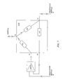
- FIG. 7 illustrates a detailed embodiment of FIG. 2-4 .
- FIG. 8 illustrates a detailed embodiment of FIG. 5-6
- FIG. 9 illustrates another detailed embodiment of FIG. 2-4
- FIG. 10 illustrates another detailed embodiment of FIG. 5-6
- FIG. 11 illustrates an embodiment of a receiving method according to the invention
- FIG. 12 illustrates an embodiment of a transmitting method according to the invention.
- the present invention will be described in the context of feeder sharing base stations utilizing GSM, however the invention is equally applicable to other network technologies such as TDMA, OFDM, WCDMA, Multi Carrier-WCDMA, OFDMA etc. Also, a mix of different network technologies is possible.
- a terminal of a first duplex filter DPX 1 is connected to an antenna feeder in order to enable separation of outgoing transmit- and incoming receive-signals on the antenna.
- An output terminal of the first duplex filter DPX 1 is connected to an input terminal of a second duplex filter DPX 2 , which in turn is connected with a terminal to a terminal of a first base station BS 1 .
- An output terminal of the first base station BS 1 is connected to an input terminal of a third duplex filter DPX 3 connected to a terminal of a second base station BS 2 .
- An output terminal of the second duplex filter DPX 2 is connected to a first input of a multi carrier power amplifier system MCPA.
- An output terminal of the third duplex filter DPX 3 is connected to a second input terminal of the multi carrier power amplifier.
- the output terminal of the multi carrier power amplifier is connected to a transmitter filter unit TXBP, which is connected to an input terminal of the first duplex filter DPX 1 .
- a signal received at the antenna is fed to the first duplex filter DPX 1 and continues via a connecting cable to the second duplex filter DPX 2 , which is connected to an input/output terminal of the first base station BS 1 .
- the base station BS 1 also comprises a coupler for relaying received signals intended for the second base station BS 2 . If a received signal is destined for the second base station BS 2 , the signal is fed from the coupler of the first base station BS 1 to the third duplex filter DPX 3 . Finally the received signal ends up at an input/output of the destination base station BS 2 .
- a first transmitted signal from the first base station BS 1 is fed from the input/output of the first base station BS 1 to the second duplex filter DPX 2 . Subsequently the signal is also fed to the first input of the multi carrier power amplifier MCPA for amplification.
- a second transmitted signal from the second base station BS 2 is initially fed from an input/output of the base station BS 2 to the third duplex filter DPX 3 . Then, the signal is fed to the second input of the multiple carrier power amplifier system MCPA for amplification.
- the two transmitted signals are then amplified and fed as one output signal from the multi carrier power amplifier system MCPA to the transmitter band-pass filter TXBP.
- the filtered signal is fed to the first duplex filter DPX 1 and finally to the antenna feeder for transmitting on the antenna.
- an embodiment of the present invention comprises a simplified filtering arrangement as compared to the above described prior art, wherein the transmit band-pass filter TXBP on the transmit path, the first and second duplex filters DPX and their connecting cable on the Rx path are reduced to one external filter module EFM, thereby simplifying the architecture.
- the filter module EFM comprises at least four terminals T 1 , T 2 , T 3 , T 4 for connection to a common antenna structure, a multi carrier power amplifier system MCPA, and at least two transceiver modules 10 , 20 .
- the first terminal T 1 is adapted to be connected to the common antenna structure, for receiving signals intended for and transmitting signals originating in the transceiver modules 10 , 20 .
- the second terminal T 2 is adapted to be connected to a duplex transmission line from the first transceiver module 10 , for providing received signals intended for the transceiver modules 10 , 20 , and to receive first transmitted signals from the first transceiver module 10 .
- the third terminal T 3 is adapted to be connected to a first input terminal of the multi carrier power amplifier system MCPA, for providing the first transmitted signals from the first transceiver module 10 to be amplified.
- the fourth terminal T 4 is adapted to be connected to an output of the multi carrier power amplifier system MCPA, for receiving combined and amplified transmitted signals originating in the two transceiver modules 10 , 20 .
- Second transmitted signals from the second transceiver module 20 are provided as input signals at a second input terminal of the multi carrier power amplifier system MCPA.
- the transceiver modules 10 , 20 can be located in one network node e.g. radio base station BS as is illustrated in FIG. 3 , or located in separate network nodes e.g. radio base stations BS 1 , BS 2 as is illustrated in FIG. 4 .
- another embodiment of the external filter module EFM comprises (in addition to the previously described four terminals T 1 , T 2 , T 3 , T 4 ) a fifth T 5 , a sixth T 6 and a seventh T 7 terminal.
- the fifth terminal T 5 is adapted for receiving signals intended for the second transceiver module 20 from the first transceiver module 10 .
- the sixth terminal T 6 is adapted for handling duplex signals for the second transceiver module 20 e.g. providing received signals to the second transceiver module 20 and receiving transmitted signals from the second transceiver module 20 .
- the seventh terminal T 7 is adapted to be connected to a second input terminal of the multi carrier power amplifier system MCPA, for providing the transmitted signals from the second transceiver module 20 to be amplified.
- the transceiver modules 10 , 20 can be located in one radio base station BS as is illustrated in FIG. 5 , or located in separate radio base stations BS 1 , BS 2 as is illustrated in FIG. 6 .
- a detailed embodiment of the filter arrangement or module EFM of FIGS. 2-4 for illustration purposes connected to a multi carrier power amplifier system MCPA, comprises three single filters RX, TX 1 , TX 2 .
- the first single filter RX connects the first terminal T 1 and the second terminal T 2 of the filter arrangement EFM.
- the second single filter TX 1 connects the second terminal T 2 and the third terminal T 3 of the filter arrangement EFM.
- the third single filter TX 2 connects the fourth terminal T 4 and the first terminal T 1 .
- the first filter RX is a receiver filter for providing signals received at the antenna to intended respective transceiver modules 10 , 20 .
- the second filter TX 1 is a transmitter filter for providing transmitted signals originating in the first transceiver module 10 to an input terminal of the multi carrier power amplifier system MCPA.
- the third filter TX 2 is also a transmitter filter for providing transmitted signals originating in the transceiver modules 10 , 20 via the multi carrier power amplifier system MCPA to the antenna for transmitting.
- This embodiment provides a receiver path with low insertion loss as compared to prior art.
- a detailed embodiment of the filter arrangement or module EFM of FIGS. 5-6 for illustration purposes connected to a multi carrier power amplifier system MCPA, comprises three single filters RX, TX 1 , TX 2 . These filters are arranged in the same manner as the single filters of the embodiment of FIGS. 2-4 .
- the external filter module EFM comprises a single duplex filter DPX arranged to connect the fifth terminal T 5 , the sixth terminal T 6 and the seventh terminal T 7 .
- FIG. 9 a further embodiment of a filter arrangement or module EFM according to the invention will be described.
- Two feedback units BP 1 , BP 2 are provided at the first terminal T 1 .
- the first feedback unit BP 1 is arranged to take a small portion of the signal to be transmitted, which comprises a combination of transmitted signals from both transceiver modules 10 , 20 and filter out i.e. remove the contribution from the first transceiver module 10 from the combination.
- the feedback unit BP 1 is configured to separate (or isolate) and analyze at least part of the combined signal originating in the second transceiver module 20 .
- the second feedback unit BP 2 is arranged to perform the same steps to filter out i.e. remove at least part of the transmitted signal from the second transceiver module 20 from the combined signal.
- the feedback units BP 1 , BP 2 comprise band pass filters which are adapted to only allow a predetermined frequency band to pass.
- the first feedback unit BP 1 comprises a first band pass filter adapted to only allow transmitted signals originating from the second transceiver module 20 to pass.
- the second feedback unit BP 2 comprises a second band pass filter adapted to only allow transmitted signals originating in the first transceiver module 10 to pass.
- the respective feedback units BP 1 , BP 2 comprise band stop filters arranged to stop predetermined frequency bands from passing.
- first and second power adjustment units M 1 , M 2 e.g. a step attenuator to respective input terminals of the multi carrier power amplifier system MCPA and supplying a feedback loop from the output of the respective feedback units BP 1 , BP 2 to the attenuators. Since this is implemented for each feeder sharing transceiver module 10 , 20 it is possible to individually adjust the respective transmitted signals in order to optimize the performance of the power amplifier system MCPA and the filter arrangement EFM. Accordingly, the accuracy of the transmit path is improved.
- the feedback units BP 1 , BP 2 are further adapted to compare the respective transmit power to a predetermined transmit power target value, which value might be different for different bandwidths. If the transmit power is higher than the predetermined transmit power target value the respective feedback units are adapted to generate a feedback signal to increase the attenuation or decrease the gain of the power adjustment units. The same applies when the transmit power is lower than the transmit power target value, which generates a feedback signal to decrease the attenuation or increase the gain.
- the target value can be set locally or set externally by means of data communication.
- Possible embodiments concerning how enable the above described attenuation or gain functionalities comprise:
- the external processor unit preferably comprises a processor located in a radio base station.
- one of the power adjustment units M 1 is located outside the filter module EFM, however it is equally possible to locate the unit within the filter module EFM, as will be described below with reference to FIG. 10 .
- FIG. 10 a preferred embodiment of the filter arrangement EFM with seven terminals T 1 , T 2 , T 3 , T 4 , T 5 , T 6 , T 7 will be described.
- This embodiment differs from the embodiment of FIG. 8 with respect to the location of the first power adjustment unit M 1 .
- the first power adjustment unit M 1 is connected between the duplex filter DPX and the seventh terminal T 7 . Thereby the entire filter functionality is contained within one external filter unit or module EFM.
- the power adjustment units M 1 , M 2 preferably are configured as electrically and/or mechanically variable attenuators such as voltage variable attenuator, digital step attenuator or electrically and/or mechanically variable amplifiers such as variable gain amplifier etc.
- FIG. 11 illustrates a general embodiment of receiving signals intended for at least two feeder sharing transceiver modules.
- the signals are received S 10 at the shared antenna system and fed S 11 to the first terminal of the filter arrangement. Subsequently, the received signal is filtered in the first filter unit and fed S 12 to the second terminal of the filter arrangement and finally fed S 13 to the first transceiver module.
- received signals intended for the second transceiver module are fed S 14 from the first transceiver module to the second transceiver module.
- the signals are fed S 14 from the first transceiver module to a fifth terminal of the filter module and are then filtered in a duplex filter unit and fed from a sixth terminal of the filter arrangement to the second transceiver module.
- FIG. 12 illustrates a general embodiment of a method for transmitting signals from at least two feeder sharing transceiver modules in a telecommunication system.
- Transmitted signals from the first transceiver module are supplied S 20 at the second terminal of the filter arrangement and are filtered in the second filter means. Subsequently, the filtered signal is fed S 21 to a third terminal of the filter arrangement and provided as an input signal at a first input of the multi carrier power amplifier system. Transmitted signals from the second transceiver module are supplied S 23 at a second input of the multi carrier power amplifier system.
- the transmitted signals from the at least two transceiver modules are combined and amplified in the multi carrier power amplifier system to an output signal and provided at an output of the amplifier. This output signal is fed S 25 to a fourth terminal of the filter arrangement for filtering in the third single filter unit. Finally, the filtered signal is fed S 26 to the first terminal and transmitted S 27 on the antenna system.
- the transmit signals from said second transceiver signal are received at a sixth terminal of the filter arrangement for filtering in the duplex filter.
- the filtered transmitted signal is fed to a seventh terminal of the external filter module, and is finally provided to the second input of the filter arrangement.
- the first input signal to the multi carrier power amplifier is adjusted, in the second power adjustment unit, in response to feedback from the second feedback means of the filter arrangement, and the second input signal to the multi carrier power amplifier is adjusted, in the first power adjustment unit, in response to feedback from the first feedback means.
- the invention enables reduction of path loss for the receive path and optionally reduction of inaccuracy in the transmit-path.
Landscapes
- Engineering & Computer Science (AREA)
- Computer Networks & Wireless Communication (AREA)
- Signal Processing (AREA)
- Transceivers (AREA)
- Transmitters (AREA)
- Exchange Systems With Centralized Control (AREA)
- Mobile Radio Communication Systems (AREA)
Abstract
Description
-
- Reduced insertion loss for the receiver path;
- Increased power accuracy of the transmit path;
- Simplified filter architecture;
-
- 1) utilizing a pre-set target value;
- 2) measuring the respective transmit power and comparing to a target value which is adapted by means of external data communication; and
- 3) the first feedback unit BP1 measuring the transmit power, providing the measurement result by means of data communication to an external processor unit which decides on how to adapt the attenuation/gain of power adjustment unit M1 and communicates the decided adaptation to the adjustment unit. The same is applicable for the second feedback unit BP2 and second power adjustment unit M2.
-
- Reduced insertion loss for the receiver path;
- Increased power accuracy of the transmit path;
- Simplified filter architecture;
Claims (15)
Applications Claiming Priority (1)
| Application Number | Priority Date | Filing Date | Title |
|---|---|---|---|
| PCT/SE2005/000938 WO2006135288A1 (en) | 2005-06-17 | 2005-06-17 | Method and arrangement for improved feeder sharing in a telecommunication system |
Related Parent Applications (1)
| Application Number | Title | Priority Date | Filing Date |
|---|---|---|---|
| PCT/SE2005/000938 A-371-Of-International WO2006135288A1 (en) | 2005-06-17 | 2005-06-17 | Method and arrangement for improved feeder sharing in a telecommunication system |
Related Child Applications (1)
| Application Number | Title | Priority Date | Filing Date |
|---|---|---|---|
| US13/854,691 Continuation US9048931B2 (en) | 2005-06-17 | 2013-04-01 | Method and arrangement for feeder sharing in a telecommunication system |
Publications (2)
| Publication Number | Publication Date |
|---|---|
| US20080267097A1 US20080267097A1 (en) | 2008-10-30 |
| US8412117B2 true US8412117B2 (en) | 2013-04-02 |
Family
ID=37532557
Family Applications (2)
| Application Number | Title | Priority Date | Filing Date |
|---|---|---|---|
| US11/917,776 Expired - Fee Related US8412117B2 (en) | 2005-06-17 | 2005-06-17 | Method and arrangement for improved feeder sharing in a telecommunication system |
| US13/854,691 Expired - Fee Related US9048931B2 (en) | 2005-06-17 | 2013-04-01 | Method and arrangement for feeder sharing in a telecommunication system |
Family Applications After (1)
| Application Number | Title | Priority Date | Filing Date |
|---|---|---|---|
| US13/854,691 Expired - Fee Related US9048931B2 (en) | 2005-06-17 | 2013-04-01 | Method and arrangement for feeder sharing in a telecommunication system |
Country Status (5)
| Country | Link |
|---|---|
| US (2) | US8412117B2 (en) |
| EP (1) | EP1891734B1 (en) |
| AT (1) | ATE422275T1 (en) |
| DE (1) | DE602005012637D1 (en) |
| WO (1) | WO2006135288A1 (en) |
Families Citing this family (5)
| Publication number | Priority date | Publication date | Assignee | Title |
|---|---|---|---|---|
| US8023999B2 (en) * | 2006-12-28 | 2011-09-20 | Alcatel Lucent | Base station architecture using decentralized duplexers |
| WO2008103083A1 (en) * | 2007-02-19 | 2008-08-28 | Telefonaktiebolaget Lm Ericsson (Publ) | An apparatus and a method for directing a received signal in an antenna system |
| CN103457622B (en) * | 2013-08-14 | 2016-08-17 | 京信通信系统(广州)有限公司 | Share communication equipment and the system of antenna feeder |
| US20160127993A1 (en) * | 2014-11-04 | 2016-05-05 | Qualcomm Incorporated | Antenna tuner control for wan/wlan antenna sharing |
| CN105530039B (en) * | 2015-12-23 | 2019-05-28 | 通号通信信息集团上海有限公司 | Combiner, combining device and signal are combined system |
Citations (4)
| Publication number | Priority date | Publication date | Assignee | Title |
|---|---|---|---|---|
| US4970479A (en) * | 1989-11-27 | 1990-11-13 | Rockwell International Corporation | Multicoupler including frequency shift filters |
| US20020009982A1 (en) * | 2000-07-14 | 2002-01-24 | Lg Electronics Inc. | Antenna sharing apparatus of base station in W-CDMA system |
| US20040214608A1 (en) * | 2003-04-25 | 2004-10-28 | Ayman Mostafa | Systems and methods for implementing fully redundant antenna hopping with multi-carrier power amplifiers and combining schemes within a base station |
| US20050136875A1 (en) | 2003-12-20 | 2005-06-23 | Ulf Skarby | Transceiver system including multiple radio base stations that share an antenna |
Family Cites Families (4)
| Publication number | Priority date | Publication date | Assignee | Title |
|---|---|---|---|---|
| US5630223A (en) * | 1994-12-07 | 1997-05-13 | American Nucleonics Corporation | Adaptive method and apparatus for eliminating interference between radio transceivers |
| US6658263B1 (en) * | 1999-12-21 | 2003-12-02 | Lucent Technologies Inc. | Wireless system combining arrangement and method thereof |
| US6658231B2 (en) | 2000-05-09 | 2003-12-02 | Sony Corporation | Receiver for user-demand information and entertainment system using wide area digital broadcast |
| US6957087B1 (en) * | 2000-10-19 | 2005-10-18 | Telefonaktiebolaget Lm Ericsson (Publ) | Power control in MCPA equipped base stations |
-
2005
- 2005-06-17 DE DE602005012637T patent/DE602005012637D1/en not_active Expired - Fee Related
- 2005-06-17 US US11/917,776 patent/US8412117B2/en not_active Expired - Fee Related
- 2005-06-17 AT AT05754785T patent/ATE422275T1/en not_active IP Right Cessation
- 2005-06-17 EP EP05754785A patent/EP1891734B1/en not_active Expired - Lifetime
- 2005-06-17 WO PCT/SE2005/000938 patent/WO2006135288A1/en not_active Ceased
-
2013
- 2013-04-01 US US13/854,691 patent/US9048931B2/en not_active Expired - Fee Related
Patent Citations (4)
| Publication number | Priority date | Publication date | Assignee | Title |
|---|---|---|---|---|
| US4970479A (en) * | 1989-11-27 | 1990-11-13 | Rockwell International Corporation | Multicoupler including frequency shift filters |
| US20020009982A1 (en) * | 2000-07-14 | 2002-01-24 | Lg Electronics Inc. | Antenna sharing apparatus of base station in W-CDMA system |
| US20040214608A1 (en) * | 2003-04-25 | 2004-10-28 | Ayman Mostafa | Systems and methods for implementing fully redundant antenna hopping with multi-carrier power amplifiers and combining schemes within a base station |
| US20050136875A1 (en) | 2003-12-20 | 2005-06-23 | Ulf Skarby | Transceiver system including multiple radio base stations that share an antenna |
Also Published As
| Publication number | Publication date |
|---|---|
| EP1891734A1 (en) | 2008-02-27 |
| US20080267097A1 (en) | 2008-10-30 |
| ATE422275T1 (en) | 2009-02-15 |
| EP1891734B1 (en) | 2009-02-04 |
| DE602005012637D1 (en) | 2009-03-19 |
| US9048931B2 (en) | 2015-06-02 |
| US20130215800A1 (en) | 2013-08-22 |
| WO2006135288A1 (en) | 2006-12-21 |
Similar Documents
| Publication | Publication Date | Title |
|---|---|---|
| US8989677B2 (en) | Apparatus and method for switching from reception to transmission | |
| US10374697B2 (en) | Distributed duplexer configuration for blocking and linearity | |
| US8694034B2 (en) | System and method for the distribution of radio-frequency signals | |
| CN108233952B (en) | Communication module | |
| US11349510B2 (en) | Radio frequency front end module and communication device | |
| US9048931B2 (en) | Method and arrangement for feeder sharing in a telecommunication system | |
| US9559746B2 (en) | Systems and methods for multi-channel transceiver communications | |
| KR20130127526A (en) | Same-band combiner using dual-bandpass channel filters | |
| KR100711015B1 (en) | Wireless system combining arrangement and method thereof | |
| US20230223965A1 (en) | Front end module and wireless device having no post amplifier bandpass filter | |
| KR101868965B1 (en) | Remote apparatus of distributed antenna system | |
| US9698859B2 (en) | Device for transmitting and receiving carrier aggregation signal | |
| US11394411B2 (en) | Transmitting/receiving system for radio signals having an integrated transmission amplifier protection function | |
| KR20020070729A (en) | Signal repeater for radio communication system | |
| CN110224704B (en) | Radio frequency system and base station equipment | |
| KR101911356B1 (en) | Rf relay apparatus using time division duplex and frequnecy division duplex | |
| EP3748868B1 (en) | Digital repeater system | |
| EP3560105B1 (en) | Fully integrated radio frequency terminal system | |
| KR101182035B1 (en) | Remote access unit with multi antena and optical wireless network for bidirectional communication | |
| US11204380B2 (en) | Module tuning using virtual gain correction | |
| CN111064481A (en) | Signal processing device and equipment | |
| CN101345931A (en) | Antenna feeder sharing device, system and method | |
| KR101911355B1 (en) | Rf relay apparatus using time division duplex and frequnecy division duplex | |
| KR100784149B1 (en) | Dual type time division transceiver | |
| CN108183714B (en) | Radio frequency device and communication equipment |
Legal Events
| Date | Code | Title | Description |
|---|---|---|---|
| AS | Assignment |
Owner name: TELEFONAKTIEBOLAGET LM ERICSSON (PUBL), SWEDEN Free format text: ASSIGNMENT OF ASSIGNORS INTEREST;ASSIGNORS:BERGLUND, BO G;SKARBY, ULF;REEL/FRAME:021360/0638;SIGNING DATES FROM 20071212 TO 20071213 Owner name: TELEFONAKTIEBOLAGET LM ERICSSON (PUBL), SWEDEN Free format text: ASSIGNMENT OF ASSIGNORS INTEREST;ASSIGNORS:BERGLUND, BO G;SKARBY, ULF;SIGNING DATES FROM 20071212 TO 20071213;REEL/FRAME:021360/0638 |
|
| FEPP | Fee payment procedure |
Free format text: PAYOR NUMBER ASSIGNED (ORIGINAL EVENT CODE: ASPN); ENTITY STATUS OF PATENT OWNER: LARGE ENTITY |
|
| AS | Assignment |
Owner name: CLUSTER LLC, DELAWARE Free format text: ASSIGNMENT OF ASSIGNORS INTEREST;ASSIGNOR:TELEFONAKTIEBOLAGET L M ERICSSON (PUBL);REEL/FRAME:030049/0541 Effective date: 20130211 |
|
| AS | Assignment |
Owner name: UNWIRED PLANET, LLC, NEVADA Free format text: ASSIGNMENT OF ASSIGNORS INTEREST;ASSIGNOR:CLUSTER LLC;REEL/FRAME:030065/0605 Effective date: 20130213 |
|
| AS | Assignment |
Owner name: CLUSTER LLC, SWEDEN Free format text: NOTICE OF GRANT OF SECURITY INTEREST IN PATENTS;ASSIGNOR:UNWIRED PLANET, LLC;REEL/FRAME:030369/0601 Effective date: 20130213 |
|
| CC | Certificate of correction | ||
| REMI | Maintenance fee reminder mailed | ||
| LAPS | Lapse for failure to pay maintenance fees | ||
| STCH | Information on status: patent discontinuation |
Free format text: PATENT EXPIRED DUE TO NONPAYMENT OF MAINTENANCE FEES UNDER 37 CFR 1.362 |
|
| STCH | Information on status: patent discontinuation |
Free format text: PATENT EXPIRED DUE TO NONPAYMENT OF MAINTENANCE FEES UNDER 37 CFR 1.362 |
|
| FP | Lapsed due to failure to pay maintenance fee |
Effective date: 20170402 |