US8410735B2 - Torque ripple suppression control device for permanent magnet motor and electric power steering system - Google Patents
Torque ripple suppression control device for permanent magnet motor and electric power steering system Download PDFInfo
- Publication number
- US8410735B2 US8410735B2 US13/009,007 US201113009007A US8410735B2 US 8410735 B2 US8410735 B2 US 8410735B2 US 201113009007 A US201113009007 A US 201113009007A US 8410735 B2 US8410735 B2 US 8410735B2
- Authority
- US
- United States
- Prior art keywords
- axis
- value
- current
- permanent magnet
- magnet motor
- Prior art date
- Legal status (The legal status is an assumption and is not a legal conclusion. Google has not performed a legal analysis and makes no representation as to the accuracy of the status listed.)
- Expired - Fee Related, expires
Links
- 230000001629 suppression Effects 0.000 title claims abstract description 94
- 238000001514 detection method Methods 0.000 claims abstract description 80
- 238000006243 chemical reaction Methods 0.000 claims abstract description 16
- 230000010349 pulsation Effects 0.000 claims description 122
- 230000014509 gene expression Effects 0.000 claims description 43
- 230000007274 generation of a signal involved in cell-cell signaling Effects 0.000 claims description 22
- 230000009467 reduction Effects 0.000 claims description 4
- 230000008859 change Effects 0.000 claims description 3
- 238000000034 method Methods 0.000 description 10
- 238000010586 diagram Methods 0.000 description 6
- 230000004069 differentiation Effects 0.000 description 6
- 230000004044 response Effects 0.000 description 5
- 230000010354 integration Effects 0.000 description 4
- 230000035945 sensitivity Effects 0.000 description 4
- 238000006467 substitution reaction Methods 0.000 description 4
- 238000004364 calculation method Methods 0.000 description 2
- 230000001010 compromised effect Effects 0.000 description 2
- 230000000694 effects Effects 0.000 description 2
- 238000000605 extraction Methods 0.000 description 2
- 230000007246 mechanism Effects 0.000 description 2
- 230000003321 amplification Effects 0.000 description 1
- 238000004458 analytical method Methods 0.000 description 1
- 238000005516 engineering process Methods 0.000 description 1
- 230000004907 flux Effects 0.000 description 1
- 238000010348 incorporation Methods 0.000 description 1
- 238000003199 nucleic acid amplification method Methods 0.000 description 1
- 238000004804 winding Methods 0.000 description 1
Images


Classifications
-
- H—ELECTRICITY
- H02—GENERATION; CONVERSION OR DISTRIBUTION OF ELECTRIC POWER
- H02P—CONTROL OR REGULATION OF ELECTRIC MOTORS, ELECTRIC GENERATORS OR DYNAMO-ELECTRIC CONVERTERS; CONTROLLING TRANSFORMERS, REACTORS OR CHOKE COILS
- H02P21/00—Arrangements or methods for the control of electric machines by vector control, e.g. by control of field orientation
- H02P21/05—Arrangements or methods for the control of electric machines by vector control, e.g. by control of field orientation specially adapted for damping motor oscillations, e.g. for reducing hunting
Definitions
- the present invention relates to a technology for suppressing torque ripple caused by an induced voltage distortion in a permanent magnet motor.
- the following is a method known in the related art that may be adopted to suppress torque ripple when the waveform of a voltage induced in a motor is rectangular when there is a distortion in the induced voltage.
- three-phase induced voltage waveforms are converted to a d-axis voltage e d and a q-axis voltage e q and the torque ripple is canceled out based upon a q-axis current command value I qref calculated as expressed in (1) below.
- T ref and ⁇ m in expression (1) respectively represent a torque command value and a mechanical angular speed at the motor.
- the q-axis current command value I qref containing a pulsation waveform can be calculated as expressed in (1) so as to achieve uniformity in the motor torque even when the waveforms of the induced voltages at the motor are rectangular.
- the torque ripple can be suppressed by executing vector control in conformance to this current command value.
- the current command value I qref contains the pulsation waveform
- the q-axis current I q corresponding to the current command value I qref must be controlled by utilizing a high-response current control system.
- the current control response frequency must be set so as to achieve the relationship expressed in (2) below. n ⁇ p/ 2 ⁇ upper limit to current control response frequency (2)
- n in expression (2) represents a wave component, the order of which is equal to or above 5% of the amplification component resulting from frequency analysis of an artificial rectangular wave simulated for the motor.
- P represents the number of poles of the motor and ⁇ represents the actual rotation rate of the motor.
- An object of the present invention is to provide a torque ripple suppression control device and an electric power steering system that enable effective utilization of the torque ripple DC component.
- a torque ripple suppression control device for a permanent magnet motor includes: a current command conversion unit that outputs a current command value based upon a torque command value input thereto from an external source; a position detector that outputs a position detection value by detecting a rotational position of the permanent magnet motor; a current detection unit that outputs a current detection value by detecting a current at the permanent magnet motor; an induced voltage coefficient setting unit that outputs, based upon the position detection value, an information signal related to an induced voltage coefficient for an induced voltage at the permanent magnet motor; a torque ripple suppression operation unit that outputs, based upon the information signal and a preset proportional gain, a current correction command value for the permanent magnet motor; a current control operation unit that outputs, based upon addition results obtained by adding together the current command value and the current correction command value and the current detection value, a voltage command value based upon which the permanent magnet motor is to be driven; and a power converter that outputs, based upon the voltage command value,
- the current command conversion unit outputs a d-axis current command value and a q-axis current command value corresponding to a d-axis and a q-axis of a rotation coordinate system of the permanent magnet motor;
- the induced voltage coefficient setting unit outputs information signals related to a d-axis induced voltage coefficient and a q-axis induced voltage coefficient corresponding to the d-axis and the q-axis;
- the torque ripple suppression operation unit outputs a d-axis current correction command value and a q-axis current correction command value corresponding to the d-axis and the q-axis;
- the current control operation unit outputs a d-axis voltage command value and a q-axis voltage command value corresponding to the d-axis and the q-axis based upon addition results obtained by adding together the d-
- the torque ripple suppression control device of the 2nd aspect of the present invention for a permanent magnet motor may further include a coordinate conversion unit that converts the d-axis voltage command value and the q-axis voltage command value to three-phase voltage command values in a stator coordinate system of the permanent magnet motor.
- the power converter outputs the voltage based upon the three-phase voltage command values.
- the induced voltage coefficient setting unit outputs, as the information signals, an induced voltage coefficient average value and a pulsation component amplitude value corresponding to at least either the d-axis or the q-axis in addition to the d-axis induced voltage coefficient and the q-axis induced voltage coefficient.
- the d-axis induced voltage coefficient and the q-axis induced voltage coefficient each change in correspondence to the position detection value whereas the average value and the pulsation component amplitude value both remain constant, unaffected by the position detection value.
- the torque ripple suppression operation unit outputs the q-axis current correction command value based upon a pulsation component in the d-axis induced voltage coefficient and the induced voltage coefficient average value corresponding to the d-axis.
- the torque ripple suppression operation unit may output the q-axis current correction command value ⁇ I q * based upon an expression below:
- the torque ripple suppression operation unit may output the q-axis current correction command value based upon the proportional gain, pulsation component amplitude values in the d-axis induced voltage coefficient and the q-axis induced voltage coefficient, a pulsation component in the q-axis induced voltage coefficient and the induced voltage coefficient average value corresponding to the d-axis.
- the torque ripple suppression operation unit may output the d-axis current correction command value ⁇ I d * based upon an expression below:
- ⁇ ⁇ ⁇ I d * - G ⁇ ( ⁇ ⁇ ⁇ K ed _ ⁇ ⁇ ⁇ K eq _ ) 2 ⁇ ⁇ ⁇ ⁇ K eq K ed _ ⁇ I q _ , with G, ⁇ ⁇ K ed , ⁇ ⁇ K eq , ⁇ ⁇ K eq , ⁇ K ed and ⁇ I q in the expression respectively representing the proportional gain, the pulsation component amplitude value in the d-axis induced voltage coefficient, the pulsation component amplitude value in the q-axis induced voltage coefficient, the pulsation component in the q-axis induced voltage coefficient, the induced voltage coefficient average value corresponding to the d-axis and a current average value corresponding to the q-axis.
- the current control operation unit may include a pulsation disturbance current control operation unit that outputs a pulsation compensation value obtained based upon the position detection value and a value representing an order of a pulsation frequency in the torque at the permanent magnet motor.
- the current control operation unit adds the pulsation compensation value to a first voltage command value, which is calculated based upon the current detection value and a sum of the current command value and the current correction command value, and outputs addition results as the voltage command value.
- the pulsation disturbance current control operation unit may include: a sine signal generation unit that generates a sine signal based upon the position detection value and the value representing the order of the pulsation frequency; a cosine signal generation unit that generates a cosine signal based upon the position detection value and the value representing the order of the pulsation frequency; a sine operation unit that determines a first operation value by multiplying the sine signal by a current deviation representing a difference between the current command value and the current detection value, by multiplying initial multiplication results by a constant and by further multiplying second multiplication results by the sine signal; and a cosine operation unit that determines a second operation value by multiplying the cosine signal by the current deviation, by multiplying initial multiplication results by the constant and by further multiplying second multiplication results by the cosine signal.
- the pulsation disturbance current control operation unit outputs, as the pulsation compensation value, a value obtained by doubling a value representing a sum of the first operation value and the second operation value.
- the sine signal generation unit and the cosine signal generation unit can respectively output a sine value and a cosine value corresponding to a value obtained by multiplying the position detection value by the value representing the order of the pulsation frequency as the sine signal and the cosine signal.
- the pulsation disturbance current control operation unit outputs the pulsation compensation value in correspondence to at least either the d-axis or the q-axis in the rotation coordinate system of the permanent magnet motor; and the current control operation unit outputs, as the voltage command value, a sum of the first voltage command value and the pulsation compensation value in correspondence to an axis for which the pulsation compensation value has been output by the pulsation disturbance current control operation unit and outputs, as the voltage command value, the first voltage command value in correspondence to an axis for which the pulsation compensation value has not been output by the pulsation disturbance current control operation unit.
- the induced voltage coefficient setting unit outputs information signals related to the d-axis induced voltage coefficient and the q-axis induced voltage coefficient based upon the position detection value, the d-axis voltage command value and the q-axis voltage command value.
- the pulsation disturbance current control operation unit outputs a d-axis pulsation compensation value and a q-axis pulsation compensation value in correspondence to a d-axis and a q-axis of a rotation coordinate system of the permanent magnet motor; and the induced voltage coefficient setting unit outputs information signals related to a d-axis induced voltage coefficient and a q-axis induced voltage coefficient corresponding to the d-axis and the q-axis based upon the position detection value, the d-axis pulsation compensation value and the q-axis pulsation compensation value.
- the power converter increases a DC torque in the permanent magnet motor by an extent equivalent to substantially half of an amplitude of a pulsating torque component in a twelfth-order harmonic in the permanent magnet motor, relative to a DC torque generated by driving the permanent magnet motor based upon a voltage command value output from the current control operation unit without adding the current correction command value to the current command value.
- An electric power steering system includes: a torque ripple suppression control device for a permanent magnet motor according to any one of the 1st through 16th aspects; the permanent magnet motor; a steering shaft mechanically connected to the permanent magnet motor via a reduction gear unit; a steering wheel mechanically connected to the steering shaft; a torque sensor that detects an operation input via the steering wheel; and a torque command unit that outputs the torque command value based upon operation detection results provided by the torque sensor.
- the present invention provides a torque ripple suppression control device and an electric power steering system that enable effective utilization of the torque ripple DC component.
- FIG. 1 is a block diagram showing the structure of a permanent magnet motor torque pulsation suppression control device achieved in an embodiment of the present invention.
- FIG. 2 shows the structure of the current control operation unit.
- FIG. 3 shows torque characteristics that may manifest when the waveform of an induced voltage at a magnet motor is a sine waveform.
- FIG. 4 shows torque characteristics that may manifest when the waveform of an induced voltage at the magnet motor is distorted.
- FIG. 5 shows the structure of the induced voltage coefficient setting unit.
- FIG. 6 presents diagrams indicating the relationship between the position signal and the induced voltage coefficient information signals.
- FIG. 7 shows the structure of the torque ripple suppression operation unit.
- FIG. 8 shows torque control characteristics that may be achieved by sinusoidally driving a magnet motor with distorted induced voltage waveform.
- FIG. 9 shows torque control characteristics that may be achieved through torque ripple suppression compensation.
- FIG. 10 is a block diagram showing the structure of a permanent magnet motor torque pulsation suppression control device achieved in a second embodiment of the present invention.
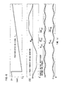
- FIG. 11 shows current characteristics that may be observed in a high-speed range when no pulsation disturbance current control is executed.
- FIG. 12 shows the structure of a current control operation unit with an added capability for pulsation disturbance current control.
- FIG. 13 shows the structure of the d-axis pulsation disturbance current control operation unit.
- FIG. 14 shows the structure of the q-axis pulsation disturbance current control operation unit.
- FIG. 15 shows current characteristics that may be observed in a high-speed range when pulsation disturbance current control is executed.
- FIG. 16 is a block diagram showing the structure of a permanent magnet motor torque pulsation suppression control device achieved in a third embodiment of the present invention.
- FIG. 17 presents an example of a structure that may be adopted in the induced voltage coefficient identification unit.
- FIG. 18 presents another example of a structure that may be adopted in the induced voltage coefficient identification unit.
- FIG. 19 presents an example of an application in which the present invention is adopted in an electric power steering system.
- FIG. 1 presents an example of a structure that may be adopted in a permanent magnet motor torque ripple suppression control device achieved in an embodiment of the present invention.
- a magnet motor 1 outputs a motor torque generated by combining a torque component attributable to magnetic fluxes from permanent magnets and a torque component attributable to the inductance at an armature winding.
- a power converter 2 outputs voltages in proportion to three-phase AC voltage command values v u *, v v * and v w * so as to adjust the output voltage and the rotation rate of the magnet motor 1 .
- a DC power source 3 provides a DC voltage to the power converter 2 .
- a current detection unit 4 detects three-phase AC currents i u , i v and i w flowing at the magnet motor 1 and outputs current detection values i uc , i vc and i wc .
- a position detector 5 detects a rotational position ⁇ of the motor and outputs a position detection value ⁇ dc .
- the position detector 5 may be constituted with, for instance, a resolver or an encoder.
- a coordinate conversion unit 6 calculates, through operation executed by using the three-phase AC current detection values i uc , i vc and i wc and the position detection value ⁇ dc mentioned above, a d-axis current detection value I dc and a q-axis current detection value I qc , and outputs the calculated current detection values.
- a current command conversion unit 7 calculates, through operation executed based upon a torque command value ⁇ * a d-axis current command value I d0 * and a q-axis current detection value I q0 *, and outputs the calculated current command values.
- An induced voltage coefficient setting unit 8 to which the position detection value ⁇ dc from the position detector 5 is input, outputs induced voltage coefficient information signals K ed , ⁇ K ed , ⁇ ⁇ K ed , K eq and ⁇ ⁇ K eq . It is to be noted that the specific information provided in these induced voltage coefficient information signals is to be described in detail later.
- a torque ripple suppression operation unit 9 outputs a d-axis current correction command value ⁇ I d * and a q-axis current correction command value ⁇ I q * calculated based upon the various information signals output from the induced voltage coefficient setting unit 8 as described above.
- the current control operation unit 10 executes proportional ⁇ integration operation based upon the current command values I d * and I q * so that the d-axis current detection value I dc and the q-axis current detection value I qc respectively conform to the current command values I d * and I q * and outputs a d-axis voltage command value V dc * and a q-axis voltage command value V qc * to a coordinate conversion unit 11 in correspondence to the proportional ⁇ integration operation results.
- the coordinate conversion unit 11 outputs three-phase AC voltage command values v u *, v v * and v w *, determined by using the d-axis voltage command value V dc * and the q-axis voltage command value V qc * provided by the current control operation unit 10 and the position detection value ⁇ dc provided by the position detector 5 , to the power converter 2 .
- Drive control for the magnet motor 1 is executed as the power converter 2 adjusts the output voltage and the rotation rate of the magnet motor 1 as described earlier based upon the voltage command values v u *, v v * and v w *.
- FIG. 2 shows the structure of the current control operation unit 10 .
- FIG. 2 shows that the d-axis current command value I d * and the d-axis current detection value I dc are input to a d-axis current control operation unit 10 a and that the q-axis current command value I q * and the q-axis current detection value I qc are input to a q-axis current control operation unit 10 b .
- the current control operation units 10 a and 10 b respectively output the d-axis voltage command value V dc * and the q-axis voltage command value V qc * by individually executing proportional ⁇ integration operation as expressed in (3) below so as to ensure that the current detection values I dc and I qc corresponding to the respective components conform to the current command values I d0 * and I q0 *.
- V dc * ( I d * - I dc ) ⁇ ( K pd + K id s )
- V qc ⁇ * ( I q * - I q ⁇ c ) ⁇ ( K pq + K iq s ) ) ( 3 )
- K pd represents a proportional gain for d-axis current control
- K id represents an integral gain for the d-axis current control
- K pq represents a proportional gain for q-axis current control
- K iq represents an integral gain for the q-axis current control.
- the position detection value ⁇ dc is obtained by detecting the rotational position ⁇ of the magnet motor 1 via the position detector 5 , which may be constituted with a resolver, an encoder, a magnetic pole position detector or the like. Based upon the position detection value ⁇ dc , the coordinate conversion units 6 and 11 execute coordinate conversion respectively as expressed in (4) and (5) below.
- the basic voltage control operation and the basic phase control operations are executed as described above.
- FIGS. 3 and 4 show the effect of the waveform e uv of an induced voltage (u-phase v-phase line voltage) at the permanent magnet motor 1 on the torque characteristics of the magnet motor 1 under control executed by the control device in FIG. 1 .
- FIG. 3 indicates the relationship that will be manifested by the induced voltage waveform e uv and the motor torque ⁇ when the induced voltage waveform e uv is sinusoidal. As FIG. 3 indicates, the motor torque ⁇ equals 100% of the command value ⁇ *, which means that stable control is achieved with no torque ripple.
- FIG. 4 indicates the relationship that may be manifested by the induced voltage waveform e uv and the motor torque ⁇ when the induced voltage waveform e uv is rectangular.
- the waveforms of the induced voltages in the individual phases each include a fifth-order harmonic component at a ration of 10%.
- the figure indicates that torque ripple ⁇ occurs at a rate as high as 20% in a sixth-order harmonic component relative to the torque command value ⁇ * representing 100%.
- FIG. 5 shows the structure of the induced voltage setting unit 8 .
- the position detection value ⁇ dc is input to a reference table 8 a at the induced voltage setting unit 8 .
- the reference table 8 a is created by storing in advance induced voltage coefficient values corresponding to various motor rotational positions, in a table format.
- the induced voltage setting unit 8 is able to output the induced voltage coefficient information signals K ed , ⁇ K ed , ⁇ ⁇ K ed , K eq and ⁇ ⁇ K eq corresponding to the position detection value ⁇ dc having been input to the table.
- FIG. 6 shows the relationship between the position detection signal ⁇ dc and the induced voltage coefficient information signals output from the induced voltage setting unit 8 .
- induced voltage coefficient information signals K ed , ⁇ K ed , ⁇ ⁇ K ed , K eq and ⁇ ⁇ K eq are output from the reference table.
- induced voltage coefficient information signals are obtained by breaking down three-phase AC induced voltage coefficients K e (each obtained by dividing an induced voltage value by an electrical angular speed ⁇ of the motor) in a stator coordinate system into a d-axis component value K ed and a q-axis component value K eq in a rotor coordinate system.
- K e AC induced voltage coefficients
- K ed and K eq in FIG. 6 respectively indicate a d-axis induced voltage coefficient and a q-axis induced voltage coefficient.
- ⁇ K ed indicates an average of d-axis induced voltage coefficients K ed
- ⁇ ⁇ K ed indicates an amplitude value of a pulsation component in the d-axis induced voltage coefficient K ed
- ⁇ ⁇ K eq indicates an amplitude value of a pulsation component in the q-axis induced voltage coefficient K eq .
- the d-axis induced voltage coefficient K ed and the q-axis induced voltage coefficient K eq both change in correspondence to the position detection value ⁇ dc .
- the average ⁇ K ed of the d-axis induced voltage coefficients and the amplitude values ⁇ ⁇ K ed and ⁇ ⁇ K eq of the pulsation components in the d-axis induced voltage coefficient and the q-axis induced voltage coefficient all remain constant even if the position detection value ⁇ dc changes.
- the structure of the torque ripple suppression operation unit 9 is shown in FIG. 7 .
- the signals K ed and ⁇ K ed are input to a subtraction unit 9 a of the torque ripple suppression operation unit 9 .
- the subtraction unit 9 a calculates the pulsation component ⁇ K ed in the d-axis induced voltage coefficient K ed as expressed in (6) below.
- ⁇ K ed K ed ⁇ K ed (6)
- the signal K eq provided from the induced voltage setting unit 8 contains no DC component, the signal K eq itself is designated as the pulsation component ⁇ K eq in the q-axis induced voltage coefficient K eq in FIG. 7 .
- the pulsation component ⁇ K ed in the d-axis induced voltage K ed and the pulsation component ⁇ K eq in the q-axis induced voltage coefficient K eq described above are all input to a current correction command operation unit 9 b together with the amplitude value ⁇ ⁇ K ed of the pulsation component in the d-axis induced voltage K ed and the amplitude value ⁇ ⁇ K eq of the pulsation component ⁇ K eq in the q-axis induced voltage coefficient K eq output from the induced voltage setting unit 8 .
- the current correction command operation unit 9 b calculates a d-axis current correction command value ⁇ I d * and a q-axis current correction command value ⁇ I q * as expressed in (7) below based upon these values input thereto.
- n in expression (7) should ideally be infinite, a fully satisfactory effect can be achieved with n set to approximately 3 in reality.
- G in expression (7) represents a proportional gain.
- the ripple component and the DC component in the torque ripple can be controlled so as to sustain a desired specific relationship by adjusting the value of the proportional gain G.
- the motor torque ⁇ m manifesting on the d-q axes may be calculated as expressed in (8) below.
- P m , L d and L q in expression (8) respectively represent the number of pairs of poles at the motor, the inductance value assumed on the d-axis and the inductance value assumed on the q-axis.
- the d-axis induced voltage coefficient K ed and the q-axis induced voltage coefficient K eq can be expressed as in (9) below by using the pulsation components ⁇ K ed and ⁇ K eq and the average ⁇ K ed of d-axis induced voltage coefficients K ed .
- the d-axis current I d and the q-axis current I q can be expressed as in (10), in which ⁇ I d and ⁇ I q respectively represent the pulsation components of the currents I d and I q and ⁇ I d and ⁇ I q respectively represent the average values of the currents I d and I q .
- the motor torque expression in (8) can be rewritten as (11) below by using expressions (9) and (10) above for substitution in expression (8).
- ⁇ m 3 2 ⁇ P m ⁇ ⁇ ( L d - L q ) ⁇ ( ⁇ ⁇ ⁇ I d + I d _ ) ⁇ ( ⁇ ⁇ ⁇ I q + I q _ ) ] + 3 2 ⁇ P m ⁇ [ ( ⁇ ⁇ ⁇ K ed + K ed _ ) ⁇ ( ⁇ ⁇ ⁇ I q + I q _ ) - ⁇ ⁇ ⁇ K eq ⁇ ( ⁇ ⁇ ⁇ I d + I d _ ) ] ( 11 )
- ⁇ m 3 2 ⁇ P m ⁇ [ ( ⁇ ⁇ ⁇ K ed + K ed _ ) ⁇ ( ⁇ ⁇ ⁇ I q + I q _ ) - ⁇ ⁇ ⁇ K eq ⁇ ( ⁇ ⁇ ⁇ I d + I d _ ) ] ( 12 )
- ⁇ m 3 2 ⁇ P m ⁇ ( ⁇ ⁇ ⁇ K ed + K ed _ ) ⁇ I q _ ( 13 )
- the pulsation component ⁇ K ed in the d-axis induced voltage coefficient K ed can be defined as in (14) below.
- ⁇ K ed ⁇ K ed ⁇ sin(6 ⁇ ) (14)
- ⁇ m 3 2 ⁇ P m ⁇ ( ⁇ ⁇ ⁇ K ed _ ⁇ sin ⁇ ( 6 ⁇ ⁇ ) + K ed _ ) ⁇ I q _ ( 15 )
- FIG. 8 indicates the torque control characteristics achieved as expressed in (15). These control characteristics are torque characteristics manifesting when the drive of the magnet motor 1 is controlled without implementing the suppression compensation according to the present invention, i.e., the torque characteristics manifesting when the drive of the magnet motor 1 is controlled by using the voltage command values output from the current control operation unit 10 without adding the current correction command values ⁇ I d * and ⁇ I q * provided from the torque ripple suppression operation unit 9 to the current command values I d0 * and I q0 *.
- FIG. 8 indicates that while the u-phase current i u , assumes a sine wave, torque pulsation (torque ripple) occurs to an extent of 20% ( ⁇ 10%) due to ⁇ K ed .
- the q-axis pulsation current command value ⁇ I q * is calculated as expressed in (16) below through operation executed in the torque ripple suppression operation unit 9 .
- n in expression (16) is an integer equal to or greater than 1.
- expression (16) can be modified as expression (17) below by assuming that the expression includes up to a third-order term.
- the motor torque ⁇ m can be calculated as expressed in (18) by using expression (17) for substitution in expression (12) described earlier.
- the intensity of the pulsating torque component in expression (18) can be expressed as in (19) below.
- the pulsating torque component can be reduced to almost 0.
- ⁇ ⁇ ⁇ I d * - G ⁇ ( ⁇ ⁇ ⁇ K ed _ ⁇ ⁇ ⁇ K eq _ ) 2 ⁇ ⁇ ⁇ ⁇ K eq K ed _ ⁇ I q _ ( 20 )
- expression (21), through which the motor torque ⁇ m is calculated, can be obtained by using expressions (17) and (20) for substitution in expression (12).
- the DC torque component can be increased by an extent equivalent to 1 ⁇ 2 of the peak-to-peak wave height value (i.e., the amplitude) of the pulsating torque component in a twelfth-order harmonic.
- FIG. 9 shows torque characteristics that may be achieved by executing such torque ripple suppression compensation.
- the sixth-order harmonic component can be greatly reduced, as indicated in FIG. 9 , compared to the sixth-order harmonic component in the characteristics in FIG. 8 observed when no suppression compensation is implemented.
- the DC torque component can be increased by an extent equivalent to 1 ⁇ 2 of the amplitude ⁇ m12 in the twelfth-order harmonic pulsating torque component at the magnet motor 1 .
- the proportional gain G the ripple component and the DC component in the torque ripple can be controlled as desired. This, in turn, enables effective utilization of the DC component in the torque ripple.
- FIG. 10 presents an example of a structure that may be adopted in the permanent magnet motor torque ripple suppression control device in the second embodiment of the present invention. While the current control operation unit 10 adopts a proportional ⁇ integration operation method in the first embodiment described earlier, the current control operation unit in this embodiment has an added capability for pulsation disturbance current control operation with sensitivity to the frequency component of the torque ripple, as described below.
- FIG. 11 shows the operational waveforms of the d-axis and q-axis current information signals I d *, I dc , I q * and I qc and the u-phase alternating current i uc that may register when the rotation rate of the permanent magnet motor 1 is in a high range.
- FIG. 11 indicates that the current detection values I dc and I qc do not conform to the respective current command values I d * and I q * when the motor rotation rate is in the high range. Under these circumstances, the extent of torque ripple is bound to increase even if suppression compensation such as that described in reference to the first embodiment is implemented.
- control that incorporates pulsation disturbance current control operation with sensitivity to the frequency component of the torque ripple is executed by the torque ripple suppression control device shown in FIG. 10 in the embodiment.
- This torque ripple suppression control device includes a current control operation unit 10 ′ in place of the current control operation unit 10 shown in FIG. 1 . It is to be noted that the other components of the torque ripple suppression control device are identical to those in FIG. 1 .
- the current control operation unit 10 ′ executes another current control operation assuming sensitivity to the frequency component of the torque ripple, as well as the current control operation shown in FIG. 2 . It then adds the output values resulting from the other current control operation to output values resulting from the current control operation shown in FIG. 2 and outputs the sums as a d-axis voltage command value V dc ** and a q-axis voltage command value V qc **.
- the current control operation unit 10 ′ adds these signals ⁇ V dc * and ⁇ V qc * respectively to the d-axis voltage command value V dc * and the q-axis voltage command value V qc * and outputs the sums as a new d-axis voltage command value V dc ** and a new q-axis voltage command value V qc **.
- the position detection value ⁇ dc provided by the position detector 5 and a constant N provided by a constant generation unit 10 ′ a 1 are input to both a cosine signal generation unit 10 ′ a 2 and a sine signal generation unit 10 ′ a 3 at the d-axis pulsation disturbance current control operation unit 10 ′ a .
- the cosine signal generation unit 10 ′ a 2 and the sine signal generation unit 10 ′ a 3 respectively output a cosine signal cos(N ⁇ dc ) and a sine signal sin(N ⁇ dc ) based upon the position detection value ⁇ dc and the constant N input thereto. These signals are then both multiplied by the d-axis current deviation ⁇ I d . Subsequently, the signals are further multiplied by a constant K d respectively at a constant multiplying unit 10 ′ a 4 and a constant multiplying unit 10 ′ a 5 .
- the position detection value ⁇ dc provided by the position detector 5 and a constant N provided by a constant generation unit 10 ′ b 1 are input to both a cosine signal generation unit 10 ′ b 2 and a sine signal generation unit 10 ′ b 3 at the q-axis pulsation disturbance current control operation unit 10 ′ b .
- the cosine signal generation unit 10 ′ b 2 and the sine signal generation unit 10 ′ b 3 respectively output a cosine signal cos(N ⁇ dc ) and a sine signal sin(N ⁇ dc ) based upon the position detection value ⁇ dc and the constant N input thereto, in much the same way as that described in reference to FIG. 13 .
- These signals are then both multiplied by the q-axis current deviation ⁇ I q .
- the signals are further multiplied by a constant K q respectively at a constant multiplying unit 10 ′ b 4 and a constant multiplying unit 10 ′ b 5 .
- the pulsation disturbance current control operation unit 10 ′ b As described earlier, the position detection value ⁇ dc and the constant N indicating the order of the torque pulsation frequency (the order of the largest harmonic component contained in a single cycle of the electric frequency) are both input to the cosine signal generation unit 10 ′ b 2 and the sine signal generation unit 10 ′ b 3 at the pulsation disturbance current control operation unit 10 ′ b , as has been described earlier.
- a cosine signal and a sine signal are respectively calculated by the cosine signal generation unit 10 ′ b 2 and the sine signal generation unit 10 ′ b 3 , each based upon a product of the input values (N ⁇ dc ).
- a harmonic component ⁇ I qrip contained in the q-axis current detection value I qc is defined as expressed in (23) below.
- ⁇ I qrip
- I a1 and I b1 respectively representing the results obtained by multiplying the output signals from the cosine signal generation unit 10 ′ b 2 and the sine signal generation unit 10 ′ b 3 by the amplitude value
- I a2 and I b2 respectively representing the results obtained by multiplying the signals I a1 and I b1 in expression (24) by a predetermined proportional gain K q at the constant multiplying units 10 ′ b 4 and 10 ′ b 5 are expressed as in (25) below.
- the q-axis pulsation compensation value ⁇ V qc * is calculated through operation executed as expressed in (26) below by using the signals I a2 and I b2 having been calculated as expressed in (25).
- Expression (26) indicates that the voltage value can be corrected with the value obtained by multiplying the harmonic component ⁇ I qrip by the gain K q .
- the d-axis pulsation compensation value ⁇ V dc * is calculated through similar operation executed in correspondence to the d-axis. These calculated values ⁇ V dc * and ⁇ V qc * are respectively added to the d-axis voltage command value V dc * and the q-axis voltage command value V qc * and the inverter output voltages are thus controlled. Through these measures, pulsation disturbance current control achieving sensitivity to the torque ripple frequency component N is enabled.
- FIG. 15 shows the control characteristics achieved by adopting the present invention.
- the control characteristics indicate that by incorporating the torque ripple suppression compensation described above, current detection values I dc and I qc can be made to conform to the respective current command values I d * and I q * with a higher degree of precision, even in a high motor rotation rate range, in comparison to the control characteristics in FIG. 11 , which are observed when no suppression compensation is implemented. In other words, the torque pulsation can be suppressed effectively in the high speed range.
- the current control operation unit 10 ′ in the second embodiment of the present invention described above may calculate only either the d-axis pulsation compensation value ⁇ V dc * or the q-axis pulsation compensation value ⁇ V qc *. Namely, the current control operation unit does not need to include both the d-axis pulsation disturbance current control operation unit 10 ′ a and the q-axis pulsation disturbance current control operation unit 10 ′ b .
- the voltage command value V dc * or V qc * should be directly output from the current control operation unit 10 ′ to the coordinate conversion unit 11 , as in the first embodiment.
- FIG. 16 presents an example of a structure that may be adopted in the permanent magnet motor torque ripple suppression control device in a third embodiment of the present invention. While the induced voltage coefficient information signals are output from the reference table 8 a in the first and second embodiments described above, induced voltage coefficient information signals generated through estimating operation executed by using the output values resulting from the pulsation disturbance current control are utilized in the torque ripple suppression compensation operation in the embodiment described below.
- the torque ripple suppression control device shown in FIG. 16 includes an induced voltage coefficient identification unit 8 ′ in place of the induced voltage setting unit 8 shown in FIGS. 1 and 10 . It is to be noted that the other components of the torque ripple suppression control device are identical to those in FIG. 10 .
- the position detection value ⁇ dc provided by the position detector 5 and the output values ⁇ V dc * and ⁇ V qc * from the d-axis pulsation disturbance current control operation unit 10 ′ a and the q-axis pulsation disturbance current control operation unit 10 ′ b in the current control operation unit 10 ′ having been described earlier in reference to the second embodiment are input to the induced voltage coefficient identification unit 8 ′.
- the induced voltage coefficient identification unit 8 ′ Based upon these input values, the induced voltage coefficient identification unit 8 ′ outputs estimated values K ed ′, ⁇ K ed ′, ⁇ K eq ′ and ⁇ ⁇ K eq ′, estimated respectively in correspondence to the induced voltage coefficient information signals K ed , ⁇ K ed , ⁇ ⁇ K ed , K eq and ⁇ ⁇ K eq explained earlier in reference to the first embodiment.
- FIG. 17 An example of a structure that may be adopted in the induced voltage coefficient identification unit 8 ′ is presented in FIG. 17 .
- the position detection signal ⁇ dc provided by the position detector 5 is input to a differentiation operation unit 8 ′ a 1 .
- the differentiation operation unit 8 ′ a 1 executes operation expressed in (27) below and outputs a motor angular speed calculation value ⁇ dc .
- the signal ⁇ dc output from the differentiation operation unit 8 ′ a 1 as described above, is input to a dividing unit 8 ′ a 2 together with the output value ⁇ V dc * from the pulsation disturbance current control operation unit 10 ′ a and input to a dividing unit 8 ′ a 3 together with the output value ⁇ V qc * from pulsation disturbance current control operation unit 10 ′ b .
- the dividing units 8 ′ a 2 and 8 ′ a 3 calculate an estimated d-axis induced voltage coefficient value K ed ⁇ and an estimated q-axis induced voltage coefficient value K eq ⁇ through operation executed as expressed in (28) below based upon the signal ⁇ dc and the value ⁇ V dc * and based upon the signal ⁇ dc and the value ⁇ V qc * having been input.
- the estimated values K ed ⁇ and K eq ⁇ having been calculated at the dividing units 8 ′ a 2 and 8 ′ a 3 are input to a memory unit 8 ′ a 4 together with the position detection signal ⁇ dc .
- the memory unit 8 ′ a 4 Based upon data related to the induced voltage coefficient information K ed , ⁇ K ed , ⁇ ⁇ K ed , K eq and ⁇ ⁇ K eq , which are stored therein in advance, the memory unit 8 ′ a 4 outputs estimated values K ed ′, ⁇ K ea ′, ⁇ ⁇ K ed ′, K eq ′ and ⁇ ⁇ K eq ′ corresponding to the signal ⁇ dc having been input.
- the data may be stored into the memory unit 8 ′ a 4 during a test operation of the device or while the device is adjusted. Furthermore, the data may be stored while the device is engaged in actual operation, instead. In any case, the data related to the induced voltage coefficient information should first be stored into the memory unit 8 ′ a 4 and the individual estimated values K ed ′, ⁇ K ed ′, ⁇ ⁇ K ed ′, K eq ′ and ⁇ ⁇ K eq ′ should then be output in correspondence to the position detection value ⁇ dc .
- the induced voltage coefficient information signals may be extracted during actual operation and these signals may be output as estimated values K ed ′, ⁇ K ed ′, ⁇ ⁇ K ed ′, K eq ′ and ⁇ ⁇ K eq ′ instead of storing in advance the data related to the induced voltage coefficient information K ed , ⁇ K ed , ⁇ K ed , K eq and ⁇ ⁇ K eq as described above.
- FIG. 18 indicates that the position detection signal ⁇ dc provided by the position detector 5 is input to a differentiation operation unit 8 ′ b 1 .
- the differentiation operation unit 8 ′ a 1 in FIG. 17 the differentiation operation unit 8 ′ b 1 outputs a motor angular speed calculation value ⁇ dc obtained through operation executed as expressed in (27).
- the signal ⁇ dc is input to a dividing unit 8 ′ b 2 together with the output value ⁇ V dc * from the pulsation disturbance current control operation unit 10 ′ a and input to a dividing unit 8 ′ b 3 together with the output value ⁇ V qc * from pulsation disturbance current control operation unit 10 ′ b.
- the dividing units 8 ′ b 2 and 8 ′ b 3 calculate an estimated d-axis induced voltage coefficient value K ea ⁇ and an estimated q-axis induced voltage coefficient value K eq ⁇ through operation executed as expressed in (28) based upon the signal ⁇ dc and the value ⁇ V dc * and based upon the signal ⁇ dc and the value ⁇ V qc * having been input.
- the estimated values K ed ⁇ and K eq ⁇ having been calculated are input to an induced voltage coefficient information extraction unit 8 ′ b 4 . Based upon these estimated values having been input thereto, the induced voltage coefficient information extraction unit 8 ′ b 4 calculates estimated values K ed ′, ⁇ K ed ′, ⁇ K ed ′, K eq ′ and ⁇ ⁇ K eq ′ corresponding to the various induced voltage coefficient information signals and outputs the estimated values having been calculated.
- FIG. 19 presents an example of an application in which the permanent magnet motor torque ripple suppression control device achieved in any of the first through third embodiments described above is adopted in an electric power steering system.
- reference numeral 101 indicates a steering wheel
- reference numeral 102 indicates a steering shaft mechanically connected to the steering wheel 101
- reference numeral 103 indicates a torque sensor
- reference numeral 104 indicates a reduction gear unit that mechanically connects the magnet motor 1 with the steering shaft 102
- reference numeral 105 indicates an ECU (engine control unit)
- reference numeral 106 indicates a rack and pinion mechanism
- reference numeral 107 indicates a linking mechanism such as a tie rod
- reference numeral 108 indicates a steerable drive wheel.
- the permanent magnet motor torque ripple suppression control device in any of the first through third embodiments is mounted at the ECU 105 . It is to be noted that the DC power source 3 , the current detection unit 4 and the position detector 5 are identical to those in FIGS. 1 , 10 and 16 .
- the torque sensor 103 detects a steering operation performed by the driver via the steering wheel 101 .
- the ECU 105 includes a torque command unit that outputs a torque command value ⁇ * to the current command conversion unit 7 of the torque ripple suppression control device based upon steering operation detection results provided by the torque sensor 103 .
- the torque ripple suppression control device controls the three-phase voltage command values so as to match the output torque with the torque command value provided by the torque command unit.
- the magnet motor 1 assists the steering operation performed by the driver via the steering wheel 101 as it applies an assisting force to the steering shaft 102 via the reduction gear unit 104 .
- the permanent magnet motor torque ripple suppression control device in the ECU 105 executes the torque ripple suppression control described earlier.
- high precision torque control is realized even if an inexpensive magnet motor 1 manifesting distortion in the induced voltages is used in the electric power steering system in FIG. 19 .
- the torque control may be executed by primarily focusing on torque ripple component suppression in a speed range over which the magnet motor 1 rotates at low speed, settings for assuring generation of a satisfactory level of DC component can be selected in a high speed range. Consequently, a sense of smooth-response steering can be created when, for instance, the driver turns the steering wheel 101 slowly.
- the magnet motor 1 rotates at high speed, a higher output from the magnet motor 1 can be assured by ensuring that a substantial DC torque component is generated.
- the magnet motor 1 can thus be provided as a compact unit, as well.
- the vector control is executed by creating voltage command values V dc * and V qc * based upon the current command values I d * and I q * and the current detection values I dc and I qc .
- the present invention is not limited to this example and may be adopted in the vector control executed by creating voltage correction values ⁇ V d and ⁇ V q based upon the current command values I d * and I q * and the current detection values I dc and I qc and calculating voltage command values V dc * and V qc * through operation executed as expressed in (29) below based upon the voltage correction values, the current command values I d * and I q *, a calculated speed value ⁇ cd and a constant related to the magnet motor 1 .
- the present invention may be adopted in vector control executed as expressed in (30) below by using second current command values I d ** and I q ** created based upon the current command values I d * and I q * and the current detection values I dc and I qc .
- the present invention may be adopted in vector control executed as expressed in (31) or (32) below instead of (29) or (30) above, in which the vector control is executed by using an induced voltage coefficient K e *.
- This alternative makes it possible to reduce the onus placed on the current control operation unit 10 in FIG. 1 or the current control operation unit 10 ′ in FIGS. 10 and 16 , which will obviously improve the conformity to the current command values.
- [ V dc * ′ V q ⁇ c * ′ ] [ R * - ⁇ cd ⁇ L * ⁇ cd ⁇ L * R * ] ⁇ [ Id * Iq * ] + [ ⁇ cd ⁇ K eq ⁇ cd ⁇ K ed ] + [ ⁇ ⁇ ⁇ V d ⁇ ⁇ ⁇ V q ] ( 31 )
- [ V dc * ′ V q ⁇ c * ′ ] [ R * - ⁇ cd ⁇ L * ⁇ cd ⁇ L * R * ] ⁇ [ Id ** Iq ** ] + [ ⁇ cd ⁇ K eq ⁇ cd ⁇ K ed ] ( 32 )
- AC currents i u , i v and i w that are directly detected by the current detector 4 are used in the first through third embodiments, AC currents i u , i v and i w may be replicated in correspondence to a DC current flowing through a one-shunt resistor installed for purposes of over-current detection at the power converter 2 .
- the present invention may also be adopted in a device that executes motor control through a method employing no position sensor.
- a phase error ⁇ c representing the deviation of the motor phase value relative a phase command value may be calculated through operation executed as expressed in (33) below based upon the voltage command values V dc * and V qc *, the current detection values I dc and I qc and the motor constant.
- ⁇ c tan - 1 ⁇ [ V dc * - R * ⁇ I dc + ⁇ dc ′ ⁇ L q * ⁇ I qc V q ⁇ c * - R * ⁇ I q ⁇ c - ⁇ dc ′ ⁇ L q * ⁇ I dc ] ( 33 )
- Motor control can then be executed by controlling an estimated frequency value ⁇ dc ′ so as to reduce the signal ⁇ c calculated as expressed in (33) to 0.
- the present invention can also be adopted effectively in conjunction with a control method employing no position sensor.
Landscapes
- Engineering & Computer Science (AREA)
- Power Engineering (AREA)
- Control Of Motors That Do Not Use Commutators (AREA)
- Control Of Ac Motors In General (AREA)
- Power Steering Mechanism (AREA)
- Steering Control In Accordance With Driving Conditions (AREA)
Abstract
Description
n×p/2×ω≦upper limit to current control response frequency (2)
- (Patent reference 1) Japanese Laid Open Patent Publication No. 2004-201487
with n, ΔKed, −Ked and −Iq in the expression respectively representing an integer, the pulsation component in the d-axis induced voltage coefficient, the induced voltage coefficient average value corresponding to the d-axis and a current average value corresponding to the q-axis.
with G, −ΔKed, −ΔKeq, −ΔKeq, −Ked and −Iq in the expression respectively representing the proportional gain, the pulsation component amplitude value in the d-axis induced voltage coefficient, the pulsation component amplitude value in the q-axis induced voltage coefficient, the pulsation component in the q-axis induced voltage coefficient, the induced voltage coefficient average value corresponding to the d-axis and a current average value corresponding to the q-axis.
ΔK ed =K ed−
ΔK ed=
ΔI qrip =|ΔI qrip|·sin(N·θ dc) (23)
Claims (17)
Applications Claiming Priority (2)
| Application Number | Priority Date | Filing Date | Title |
|---|---|---|---|
| JP2010-009044 | 2010-01-19 | ||
| JP2010009044A JP5417195B2 (en) | 2010-01-19 | 2010-01-19 | Torque ripple suppression control device for permanent magnet motor, electric power steering system |
Publications (2)
| Publication Number | Publication Date |
|---|---|
| US20110175556A1 US20110175556A1 (en) | 2011-07-21 |
| US8410735B2 true US8410735B2 (en) | 2013-04-02 |
Family
ID=44277138
Family Applications (1)
| Application Number | Title | Priority Date | Filing Date |
|---|---|---|---|
| US13/009,007 Expired - Fee Related US8410735B2 (en) | 2010-01-19 | 2011-01-19 | Torque ripple suppression control device for permanent magnet motor and electric power steering system |
Country Status (2)
| Country | Link |
|---|---|
| US (1) | US8410735B2 (en) |
| JP (1) | JP5417195B2 (en) |
Cited By (3)
| Publication number | Priority date | Publication date | Assignee | Title |
|---|---|---|---|---|
| US20130093369A1 (en) * | 2011-10-14 | 2013-04-18 | Ford Global Technologies, Llc | Controlling torque ripple in interior permanent magnet machines |
| US20130119900A1 (en) * | 2011-11-10 | 2013-05-16 | Ford Global Technologies, Llc | Motor torque ripple compensation |
| US12308779B2 (en) | 2020-04-01 | 2025-05-20 | Cummins Inc. | Torque ripple compensation in a motor control system |
Families Citing this family (33)
| Publication number | Priority date | Publication date | Assignee | Title |
|---|---|---|---|---|
| JP5446988B2 (en) * | 2010-02-25 | 2014-03-19 | 株式会社明電舎 | Torque ripple suppression control device and control method for rotating electrical machine |
| JP2011211815A (en) * | 2010-03-30 | 2011-10-20 | Kokusan Denki Co Ltd | Controller of permanent magnet motor |
| KR101739911B1 (en) * | 2011-04-19 | 2017-05-26 | 한국전자통신연구원 | Motor control apparatus and control method thereof |
| JP2013046514A (en) * | 2011-08-25 | 2013-03-04 | Semiconductor Components Industries Llc | Drive signal generation circuit |
| US8766578B2 (en) | 2012-02-27 | 2014-07-01 | Canadian Space Agency | Method and apparatus for high velocity ripple suppression of brushless DC motors having limited drive/amplifier bandwidth |
| US8924082B2 (en) | 2012-03-30 | 2014-12-30 | Steering Solutions Ip Holding Corporation | System and method for controlling a motor |
| DE102012209369A1 (en) * | 2012-06-04 | 2013-12-05 | Siemens Aktiengesellschaft | Control device for eliminating disturbances in the network |
| JP6085102B2 (en) * | 2012-06-06 | 2017-02-22 | ジョンソンコントロールズ ヒタチ エア コンディショニング テクノロジー(ホンコン)リミテッド | Motor control device and air conditioner using the same |
| FR2994355B1 (en) * | 2012-08-06 | 2014-08-29 | Renault Sa | SYSTEM FOR CONTROLLING THE ELECTROMAGNETIC TORQUE OF AN ELECTRIC MACHINE, IN PARTICULAR FOR A MOTOR VEHICLE |
| US9663139B2 (en) | 2013-02-26 | 2017-05-30 | Steering Solutions Ip Holding Corporation | Electric motor feedforward control utilizing dynamic motor model |
| US9136785B2 (en) | 2013-03-12 | 2015-09-15 | Steering Solutions Ip Holding Corporation | Motor control system to compensate for torque ripple |
| US9143081B2 (en) | 2013-03-14 | 2015-09-22 | Steering Solutions Ip Holding Corporation | Motor control system having bandwidth compensation |
| KR101723333B1 (en) * | 2013-07-02 | 2017-04-04 | 미쓰비시덴키 가부시키가이샤 | Motor control device |
| US10389289B2 (en) * | 2014-02-06 | 2019-08-20 | Steering Solutions Ip Holding Corporation | Generating motor control reference signal with control voltage budget |
| FR3018647B1 (en) * | 2014-03-11 | 2016-02-26 | Renault Sas | METHOD AND SYSTEM FOR CONTROLLING A THREE - PHASE ELECTRIC MACHINE OF A MOTOR VEHICLE. |
| US10003285B2 (en) | 2014-06-23 | 2018-06-19 | Steering Solutions Ip Holding Corporation | Decoupling current control utilizing direct plant modification in electric power steering system |
| CN104378026B (en) * | 2014-11-24 | 2017-02-01 | 江苏科技大学 | Brushless DC motor high-speed torque pulse control device and method |
| US9809247B2 (en) | 2015-01-30 | 2017-11-07 | Steering Solutions Ip Holding Corporation | Motor control current sensor loss of assist mitigation for electric power steering |
| CN105245144A (en) * | 2015-10-30 | 2016-01-13 | 中国兵器工业集团第二O二研究所 | Non-steady-state-error-displacement-based position servo system proportional control method |
| US10090788B2 (en) * | 2016-03-03 | 2018-10-02 | Robert Bosch Gmbh | Optimal torque ripple reduction through current shaping |
| US10135368B2 (en) | 2016-10-01 | 2018-11-20 | Steering Solutions Ip Holding Corporation | Torque ripple cancellation algorithm involving supply voltage limit constraint |
| US11499537B2 (en) * | 2017-12-17 | 2022-11-15 | Microchip Technology Incorporated | Closed loop torque compensation for compressor applications |
| CN109831133B (en) * | 2019-02-20 | 2020-01-17 | 浙江大学 | Method and system for suppressing torque ripple of permanent magnet motor |
| JP7169587B2 (en) * | 2019-03-28 | 2022-11-11 | 株式会社アイシン | Rotating electric machine control system |
| JP7039518B2 (en) | 2019-04-17 | 2022-03-22 | 株式会社 日立パワーデバイス | Outdoor unit of motor drive device and air conditioner using it |
| JP6641053B1 (en) * | 2019-04-25 | 2020-02-05 | 三菱電機株式会社 | Electric motor control device and electric power steering device |
| GB2596979B (en) * | 2019-05-20 | 2023-07-19 | Mitsubishi Electric Corp | Motor drive device, compressor drive device, and refrigeration cycle system |
| JP7363176B2 (en) * | 2019-08-07 | 2023-10-18 | 日本精工株式会社 | Motor control device, motor control method, and electric power steering device |
| CN110880895B (en) * | 2019-11-26 | 2021-02-05 | 华中科技大学 | Determination method of q-axis current compensation value of permanent magnet synchronous motor and pulsation suppression method |
| CN112953333A (en) * | 2021-03-01 | 2021-06-11 | 北京航天控制仪器研究所 | Permanent magnet synchronous motor torque ripple suppression method based on adaptive filter |
| JP2023005629A (en) * | 2021-06-29 | 2023-01-18 | 株式会社日立産機システム | Power conversion device |
| CN113922710A (en) * | 2021-09-24 | 2022-01-11 | 美的威灵电机技术(上海)有限公司 | Motor control method, control device, control system and readable storage medium |
| CN113852315B (en) * | 2021-10-27 | 2024-07-23 | 镇江转能电子科技有限公司 | Device and method for generating rotor torsional vibration |
Citations (8)
| Publication number | Priority date | Publication date | Assignee | Title |
|---|---|---|---|---|
| US6081087A (en) * | 1997-10-27 | 2000-06-27 | Matsushita Electric Industrial Co., Ltd. | Motor control apparatus |
| JP2004120841A (en) * | 2002-09-25 | 2004-04-15 | Hitachi Ltd | AC motor control device and semiconductor device |
| JP2004201487A (en) | 2002-11-28 | 2004-07-15 | Nsk Ltd | Motor and its drive control device |
| US6859001B2 (en) * | 2003-07-24 | 2005-02-22 | General Electric Company | Torque ripple and noise reduction by avoiding mechanical resonance for a brushless DC machine |
| JP2010057217A (en) * | 2008-08-26 | 2010-03-11 | Meidensha Corp | Torque pulsation suppression device of electric motor, and suppression method |
| US7808202B2 (en) * | 2006-12-28 | 2010-10-05 | Hitachi Industrial Equipment Systems Co., Ltd. | Beat-less controller for permanent magnet motor |
| US7952308B2 (en) * | 2008-04-04 | 2011-05-31 | GM Global Technology Operations LLC | Method and apparatus for torque ripple reduction |
| US8285451B2 (en) * | 2005-03-17 | 2012-10-09 | Nsk Ltd. | Method and apparatus for controlling electric power steering system |
Family Cites Families (2)
| Publication number | Priority date | Publication date | Assignee | Title |
|---|---|---|---|---|
| JP3679915B2 (en) * | 1998-03-13 | 2005-08-03 | 株式会社東芝 | Power converter |
| JP5168448B2 (en) * | 2007-02-26 | 2013-03-21 | 株式会社ジェイテクト | Motor control device and electric power steering device |
-
2010
- 2010-01-19 JP JP2010009044A patent/JP5417195B2/en not_active Expired - Fee Related
-
2011
- 2011-01-19 US US13/009,007 patent/US8410735B2/en not_active Expired - Fee Related
Patent Citations (8)
| Publication number | Priority date | Publication date | Assignee | Title |
|---|---|---|---|---|
| US6081087A (en) * | 1997-10-27 | 2000-06-27 | Matsushita Electric Industrial Co., Ltd. | Motor control apparatus |
| JP2004120841A (en) * | 2002-09-25 | 2004-04-15 | Hitachi Ltd | AC motor control device and semiconductor device |
| JP2004201487A (en) | 2002-11-28 | 2004-07-15 | Nsk Ltd | Motor and its drive control device |
| US6859001B2 (en) * | 2003-07-24 | 2005-02-22 | General Electric Company | Torque ripple and noise reduction by avoiding mechanical resonance for a brushless DC machine |
| US8285451B2 (en) * | 2005-03-17 | 2012-10-09 | Nsk Ltd. | Method and apparatus for controlling electric power steering system |
| US7808202B2 (en) * | 2006-12-28 | 2010-10-05 | Hitachi Industrial Equipment Systems Co., Ltd. | Beat-less controller for permanent magnet motor |
| US7952308B2 (en) * | 2008-04-04 | 2011-05-31 | GM Global Technology Operations LLC | Method and apparatus for torque ripple reduction |
| JP2010057217A (en) * | 2008-08-26 | 2010-03-11 | Meidensha Corp | Torque pulsation suppression device of electric motor, and suppression method |
Cited By (4)
| Publication number | Priority date | Publication date | Assignee | Title |
|---|---|---|---|---|
| US20130093369A1 (en) * | 2011-10-14 | 2013-04-18 | Ford Global Technologies, Llc | Controlling torque ripple in interior permanent magnet machines |
| US8786223B2 (en) * | 2011-10-14 | 2014-07-22 | Ford Global Technologies, Llc | Controlling torque ripple in interior permanent magnet machines |
| US20130119900A1 (en) * | 2011-11-10 | 2013-05-16 | Ford Global Technologies, Llc | Motor torque ripple compensation |
| US12308779B2 (en) | 2020-04-01 | 2025-05-20 | Cummins Inc. | Torque ripple compensation in a motor control system |
Also Published As
| Publication number | Publication date |
|---|---|
| JP2011151883A (en) | 2011-08-04 |
| US20110175556A1 (en) | 2011-07-21 |
| JP5417195B2 (en) | 2014-02-12 |
Similar Documents
| Publication | Publication Date | Title |
|---|---|---|
| US8410735B2 (en) | Torque ripple suppression control device for permanent magnet motor and electric power steering system | |
| US6465975B1 (en) | Method and system for controlling torque in permanent magnet brushless electric motors | |
| US8779701B2 (en) | Control apparatus for permanent magnet motor | |
| EP1470988B2 (en) | Electric power steering apparatus | |
| US9136785B2 (en) | Motor control system to compensate for torque ripple | |
| KR100655702B1 (en) | Permanent Magnet Synchronous Motor Control Method | |
| US9143081B2 (en) | Motor control system having bandwidth compensation | |
| JP4736805B2 (en) | Electric power steering device | |
| JP4039317B2 (en) | Electric power steering device | |
| EP2582036A2 (en) | Parameter estimating apparatus for permanent magnet synchronous motor driving system | |
| EP1777806A2 (en) | Motor drive control apparatus and electric power steering apparatus | |
| JP4881635B2 (en) | Vector controller for permanent magnet motor | |
| US8928265B2 (en) | Sensorless field-oriented control (FOC) without current sampling for motors | |
| US20090009127A1 (en) | Motor control device and electric power steering device using the same | |
| WO2021171679A1 (en) | Motor drive device, outdoor unit of air conditioner using same, and motor drive control method | |
| JP5136839B2 (en) | Motor control device | |
| JP4764785B2 (en) | Control device for synchronous motor | |
| JP7600583B2 (en) | Motor device and map setting method | |
| JP2010029027A (en) | Motor control device | |
| US12143038B2 (en) | Rotary machine control device | |
| JP5652701B2 (en) | Motor drive control device | |
| KR20180080730A (en) | Method and system for controlling motor | |
| JP7412106B2 (en) | Motor control device and motor control method | |
| JP5482625B2 (en) | Rotating machine control device | |
| JP2012239281A (en) | Motor controller |
Legal Events
| Date | Code | Title | Description |
|---|---|---|---|
| AS | Assignment |
Owner name: KOKUSAN DENKI CO., LTD., JAPAN Free format text: ASSIGNMENT OF ASSIGNORS INTEREST;ASSIGNORS:TOBARI, KAZUAKI;IWAJI, YOSHITAKA;NAKATSUGAWA, JUNNOSUKE;AND OTHERS;SIGNING DATES FROM 20110222 TO 20110301;REEL/FRAME:026036/0229 |
|
| STCF | Information on status: patent grant |
Free format text: PATENTED CASE |
|
| FEPP | Fee payment procedure |
Free format text: PAYOR NUMBER ASSIGNED (ORIGINAL EVENT CODE: ASPN); ENTITY STATUS OF PATENT OWNER: LARGE ENTITY |
|
| FPAY | Fee payment |
Year of fee payment: 4 |
|
| FEPP | Fee payment procedure |
Free format text: MAINTENANCE FEE REMINDER MAILED (ORIGINAL EVENT CODE: REM.); ENTITY STATUS OF PATENT OWNER: LARGE ENTITY |
|
| LAPS | Lapse for failure to pay maintenance fees |
Free format text: PATENT EXPIRED FOR FAILURE TO PAY MAINTENANCE FEES (ORIGINAL EVENT CODE: EXP.); ENTITY STATUS OF PATENT OWNER: LARGE ENTITY |
|
| STCH | Information on status: patent discontinuation |
Free format text: PATENT EXPIRED DUE TO NONPAYMENT OF MAINTENANCE FEES UNDER 37 CFR 1.362 |
|
| FP | Lapsed due to failure to pay maintenance fee |
Effective date: 20210402 |