US840995A - Method of polystation signaling. - Google Patents
Method of polystation signaling. Download PDFInfo
- Publication number
- US840995A US840995A US273460A US1905273460A US840995A US 840995 A US840995 A US 840995A US 273460 A US273460 A US 273460A US 1905273460 A US1905273460 A US 1905273460A US 840995 A US840995 A US 840995A
- Authority
- US
- United States
- Prior art keywords
- clapper
- signaling
- armature
- reed
- stroke
- Prior art date
- Legal status (The legal status is an assumption and is not a legal conclusion. Google has not performed a legal analysis and makes no representation as to the accuracy of the status listed.)
- Expired - Lifetime
Links
- 238000000034 method Methods 0.000 title description 11
- 230000011664 signaling Effects 0.000 title description 8
- 235000014676 Phragmites communis Nutrition 0.000 description 15
- 230000000737 periodic effect Effects 0.000 description 4
- 244000273256 Phragmites communis Species 0.000 description 2
- 230000001186 cumulative effect Effects 0.000 description 2
- NRUQNUIWEUZVLI-UHFFFAOYSA-O diethanolammonium nitrate Chemical compound [O-][N+]([O-])=O.OCC[NH2+]CCO NRUQNUIWEUZVLI-UHFFFAOYSA-O 0.000 description 2
- 241000030538 Thecla Species 0.000 description 1
- 230000004075 alteration Effects 0.000 description 1
- 230000003321 amplification Effects 0.000 description 1
- 238000010276 construction Methods 0.000 description 1
- 239000000696 magnetic material Substances 0.000 description 1
- 230000000051 modifying effect Effects 0.000 description 1
- 238000003199 nucleic acid amplification method Methods 0.000 description 1
- 238000004080 punching Methods 0.000 description 1
- 238000011084 recovery Methods 0.000 description 1
- 230000003014 reinforcing effect Effects 0.000 description 1
- 210000004722 stifle Anatomy 0.000 description 1
Images
Classifications
-
- H—ELECTRICITY
- H04—ELECTRIC COMMUNICATION TECHNIQUE
- H04Q—SELECTING
- H04Q3/00—Selecting arrangements
Definitions
- Patented-T an. 8, 1907.
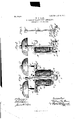
- FIG. 1 is aside view of a polarized signal .bell orringer'embodying my invention
- Fig. 3 is a perspective view removed.
- Q Q is a pair of ringer-magnets mounted upon the yoke B, which also carries the bent permanent mag- "net M, as shown.
- the cores g g of the elec tromagnets protrude at the lower ends, and upon them or u on the sleeve surrounding is of non-magnetic material extending from pole to pole and adjustably clamped thereto and having front andback downwardlym, for the reception of the studs d d on gong-strokes, I use three expedients-theture and so adjust the gongs that each end of,
- Each left blank has a wing c, a leaf 0, and a long stem 0
- Each right blank has a wing c, a leaf c and a stem '0
- the spring (1 is placed. between the two leaves 0 and 0 which are riveted together through the spring.
- the stems c and c are thenalso riveted together, and the cylindrical placed upon the rod thus produced.
- the ends of the spring (1 being secured in the blocks al d the structure of 3 is com lete and is read for assembling in'the comp ete ringer, as s own in Figs. 1 and 2.
- My selective reed is thus formed of the parts D and C, and its exact period is de it is tuned by up or down until the moving the clapper c is possible to determine the exact point upon the clapper-rod upon which the clapper of a given Wei ht must be placed to give the desired resu t. v
- the clapper strikes the gong and instantly recoils. All this on account of the magnitude of the cumulative force at the time of stroke is accomplished substantially in the natural period of the parts. Hence the recoil from one side stroke assists in the or, to put it another way, energy'is stored up in the yielding clapper C to snap back and start the next stroke, the innate capabilities of all the parts bein thus utilized and current, spring, and stro c all acting well together.
- Each worm has a head W or W, and its shank is mounted to turn in drop-bearings b 6, formed upon the yoke B.
- The'sudden stoppage of the energizing-armature is of importance in order to give this instantaneous stroke, and the use of stiff and normally unresponsive parts is of importance in order to prevent the storing up of energy in beats of frequency called for. It is to be observed that I make the spring d stiff, and by reason of the cross-connection thereon of the leaves of the armature there is a torsional that is to say, a very strongresistance to the first movements on the partof the armature.
- the spring (1 itself maybe tuned like a reed; but whether it is or not it is so stiff that no momentary current impulses will budge the armature, this only being accomplished by the normal increments of the proper periodic currents.
- the method of selective, harmonic signaling which comprises the following steps: communicating to astifi tuned reed, successive, small increments of periodic-energy of proper frequency and thereby raising it from a state of inaction to a state of active vibration, storing up energy in said reed, andvibrating the same with gradually-increasing amplitudes, and finally at the point of'maximum amplification interposing a positive stop to render dead a portion of the vibrating whereby the entire cumulareed structure tive energy will be imparted suddenly to the remainderof the reed structure to roduce a stroke or sounding movement at sue accelerated velocity as not .to retard or, alter the normal periodic vibration of the reed structure as a whole.
Landscapes
- Engineering & Computer Science (AREA)
- Computer Networks & Wireless Communication (AREA)
- Percussion Or Vibration Massage (AREA)
Description
PATENTED JAN. 8, 1907.
'W'. W. DEAN. METHOD OF POLYSTATION SIGNALING. APPLICATION FILED AUG.9, 1905.
THE NORRIS Pia-15x5 0a., wnsnmammn c.
1'0 a/ZZ whom it may concern:
UNITED STATES PATENT OFFICE.
WILLIAMW. DEAN, OF ELYRIA, OHIO, ASSIGNOR To THE DEAN ELECTRIC COMPANY, or ELYRIA, OHIO, A CORPORATION OF OHIO.
METHOD OF POLYSTATION SIGNALING.
' Specification of Letters Patent,
Patented-T an. 8, 1907.
Original application filed May 19, 1905, Serial No. 261,1 82. Divided and this application filed August 9, 1906. Sefial No. 273,460.
Be it known that I, WILLIAM W- DEAN, a citizen of the United States, residing at Elyria, in the'county of Lorain and State of Ohio, have invented certain new and useful Improvements in Methods of Polystation Signaling, of which the following is a specification, reference being had therein to the ac- 'companying drawings. My invention relates to electrical signaling, and particularly to what is known as harmonic or selective ,signaling for telee disclosed in my 261,132, of which the present application is a division. I In such systems where more than one station is served over a single line modern standard practice calls for the employment of'signaling means by which one station may be called up without alarming the other or any'of the others, if there be several; In former systems devised by me I have employed a number of tuned vibrating. reeds at the several stations, each reed responding to a certain frequency of alternating or intermittent current only. The reeds employed constituted the clapper-rods of polarized ringers, and the clappers were adjusted to strike the gongs without the armaturestouching the pole-pieces. With such an arrangement the initial rate or period of vibrationof each clapper-rbd is'somewhat modi-- fied by contact with the gongs, and-hence I' found it necessary to resort to undertuningor overtuning the current or the mechanical. parts in order that the current throw upon the line to ring a particular station should :orrespond in periodicity to the modified or operativeperiodicity of the reed and clapper at thedesired" substation. My present invention, while, asd have. stated, it includes the feature of a tuned reed at each station, is an improvement in every way and is to be distinguished from my former inventions bythe following. radically-different principle and method ofoperation; In'the former case I was forced to use gongs of different sizes, and it was necessary to have a very nice adjustment of relative ire uencies, as well as a careful adjustment 0 the moving mechan ical parts. In the present case I abandon all overtunihg and undertuning entirely and adjust my reed to respond .to its own natural frequency, and this being determined th current can be supplied at a corresponding frequency with absolute certainty. 11 order to overcome the modifying effects of the first, a very stifl springmountin for the armature. @11 clapper-rod; secon I expose the armature to a cumulatively-increasing force as it vibrates, and, third, I expose the naked pole-pieces to the ends of the armathe armature will strike its pole-piece before the clapper-rod touches the'g'ong, the clapper then springing over to strike the gong, and thus getting a very quick return. In practice the distance between the clapper and the gong may be, say, one thirty-second ofan inch. With this construction and adjust tone from the gongs and perfect certainty of of operation in selection. It will be observed that my invention tus for practicing the method. In the prestures, such as 'a spring-mounting of the armature and the means for tuning b 'sliding the cla per up and down the rod; ut it is of these or any other specific limitations, being practicable with many different forms of apparatus. I My invention will be fully understood upon reading the following detailed description in connection with' the accompanying drawings, forming a part hereof, in which-: 1
I Figure 1 is aside view of a polarized signal .bell orringer'embodying my invention; Fig.
to t 'e right, and Fig. 3 is a perspective view removed.
Referring to the drawings, Q Q is a pair of ringer-magnets mounted upon the yoke B, which also carries the bent permanent mag- "net M, as shown. The cores g g of the elec tromagnets protrude at the lower ends, and upon them or u on the sleeve surrounding is of non-magnetic material extending from pole to pole and adjustably clamped thereto and having front andback downwardlym, for the reception of the studs d d on gong-strokes, I use three expedients-theture and so adjust the gongs that each end of,
of the clapper-rod with its connected' .parts ment I get a very sharp, clear, and powerful really covers both a method and the appara ent case I shall describe some specific feaquite o vious that my method is independent -2 is section on the line 00 a: of Fig. 1 looking 'them is carried t e armature-yoke A. This turned extensions (1 a slotted, as shown at the armature-support D. hese'studs are rod out of punchings, in two halves, a
' the blanks these would termined, or, in other words,
opposite stroke,
'rected by securing the clapper c is exact pitchis reached which i desired. .01 course in making these bells in quantities it cumulative force soon formed upon the terminal blocks d d con the stiff springd, Whose ends are riveted or otherwise secured in slots in the blocks. The studs are threaded'and receive the nuts d (1 which clamp the extensions of the yoke firmly upon the blocks (1 d thereby structure D in place. The armature C is formed integral with the clapperright'and a left. Of course in making be all the same, but in forming up the right wouldbe turned one way and the left the other. Each left blank has a wing c, a leaf 0, and a long stem 0 Each right blank has a wing c, a leaf c and a stem '0 In assembling these parts the spring (1 is placed. between the two leaves 0 and 0 which are riveted together through the spring. The stems c and c are thenalso riveted together, and the cylindrical placed upon the rod thus produced. The ends of the spring (1 being secured in the blocks al d the structure of 3 is com lete and is read for assembling in'the comp ete ringer, as s own in Figs. 1 and 2. My selective reed is thus formed of the parts D and C, and its exact period is de it is tuned by up or down until the moving the clapper c is possible to determine the exact point upon the clapper-rod upon which the clapper of a given Wei ht must be placed to give the desired resu t. v
In operation when current of any particu lar frequency is thrown upon the. line the reed or clapperrod of corresponding period will commence to buzz, and as it buzzes' the armature-wings c 0- will approach to and recede from. the pole-pieces g During each approach and recession the amplitude of vibration isv increased, and the force exerted by the pole-pieces is increased corre spondingly. .Ac'tion and reaction thus 'succeeding and reinforcing each the other, the causes one armature end toforcibly strike its pole-piece, whereupon it will stop; but the clapper 0 will continue its'travel, the clapper-rod'C springing to permit this. The clapper strikes the gong and instantly recoils. All this on account of the magnitude of the cumulative force at the time of stroke is accomplished substantially in the natural period of the parts. Hence the recoil from one side stroke assists in the or, to put it another way, energy'is stored up in the yielding clapper C to snap back and start the next stroke, the innate capabilities of all the parts bein thus utilized and current, spring, and stro c all acting well together.
In order that the adjustment of the gongs may be not only accurate but permanent, I mount each gong G or G upon a post 9 or g,
I without any overthrow -ticed.that is 'to say,
ward end to engage a worm w or w. Each worm has a head W or W, and its shank is mounted to turn in drop-bearings b 6, formed upon the yoke B. By means of a wrench the worms can be turned 'to adjust the gongsexactly,
ordinary use or misuse will move them.
It will be apparent from the foregoing description that my method consists in exact tuning, but -mechanical overthrow, as contradistinguish'ed from exact adjustment but with 'overtuning. The present method may be stated in a few words, as follows: A reed is cumula tively flexed to store up energy, the point of reversal or cut-off of the energy bein determined at this mechanism, leaving t e reed or moving body to give the actual stroke and to take the corresponding recovery by means of the stored energy thus suddenly concentrated and released. It will be observed that the instantaneous stroke is of great importance. The'sudden stoppage of the energizing-armature is of importance in order to give this instantaneous stroke, and the use of stiff and normally unresponsive parts is of importance in order to prevent the storing up of energy in beats of frequency called for. It is to be observed that I make the spring d stiff, and by reason of the cross-connection thereon of the leaves of the armature there is a torsional that is to say, a very strongresistance to the first movements on the partof the armature. The spring (1 itself maybe tuned like a reed; but whether it is or not it is so stiff that no momentary current impulses will budge the armature, this only being accomplished by the normal increments of the proper periodic currents.
I am aware that there are many changes in detail that. may .be made in the invention 'thus described without departing from the any but the particular and when so adjusted no spirit or the principles involved, and I wish 1t understood quite clearly that I do not limit myself to the specific form shown for my ringer, but include within the scope of the claims which I shall make all possible forms by which the invention may be pracby which the principles upon which I rely may be incorporated and brought under control.
Having thus described my invention, what I claim, and desire to secure by'Le'tters Patent, is I a l. The method of selective, harmonic signaling, which consists in vibrating a tuned body by means of periodic increments of energy, causing said energyto be stored in said body until a desired totality is reached,then, instantaneously interrupting the vibration and utilizing the stored energy to flex the l body to produce a stroke of such short duration as not appreciably to retard or alter the normal or periodic movement of the vibrating body.
2. The method of selective, harmonic signaling which comprises the following steps: communicating to astifi tuned reed, successive, small increments of periodic-energy of proper frequency and thereby raising it from a state of inaction to a state of active vibration, storing up energy in said reed, andvibrating the same with gradually-increasing amplitudes, and finally at the point of'maximum amplification interposing a positive stop to render dead a portion of the vibrating whereby the entire cumulareed structure tive energy will be imparted suddenly to the remainderof the reed structure to roduce a stroke or sounding movement at sue accelerated velocity as not .to retard or, alter the normal periodic vibration of the reed structure as a whole.
is utilized to flex the body to produce a stroke of such short duration that the retardation or alteration ofthe natural rate of vibration is rendered ne ligible,
In testimony whereofl affix my signature in presence of two witnesses.
WILLIAM w. DEAN.
Witnesses:
A. D. T. LIBBY, I Gno'. A.-Scov1:LLE.
' said vibration, whereby the stored-up energy w
Priority Applications (1)
| Application Number | Priority Date | Filing Date | Title |
|---|---|---|---|
| US273460A US840995A (en) | 1905-05-19 | 1905-08-09 | Method of polystation signaling. |
Applications Claiming Priority (2)
| Application Number | Priority Date | Filing Date | Title |
|---|---|---|---|
| US26113205A US1125490A (en) | 1905-05-19 | 1905-05-19 | Electrical signaling. |
| US273460A US840995A (en) | 1905-05-19 | 1905-08-09 | Method of polystation signaling. |
Publications (1)
| Publication Number | Publication Date |
|---|---|
| US840995A true US840995A (en) | 1907-01-08 |
Family
ID=2909466
Family Applications (1)
| Application Number | Title | Priority Date | Filing Date |
|---|---|---|---|
| US273460A Expired - Lifetime US840995A (en) | 1905-05-19 | 1905-08-09 | Method of polystation signaling. |
Country Status (1)
| Country | Link |
|---|---|
| US (1) | US840995A (en) |
-
1905
- 1905-08-09 US US273460A patent/US840995A/en not_active Expired - Lifetime
Similar Documents
| Publication | Publication Date | Title |
|---|---|---|
| US840995A (en) | Method of polystation signaling. | |
| US174465A (en) | Improvement in telegraphy | |
| US1098834A (en) | Electric bell. | |
| US1852045A (en) | Signaling arrangement for telephone lines | |
| US1896195A (en) | Electromagnetic signaling device | |
| US1452925A (en) | Wireless telegraph calling device | |
| US2692380A (en) | Ringer | |
| US915334A (en) | Harmonic ringer. | |
| US929995A (en) | Selective-ringing magneto-bell. | |
| US1125495A (en) | Harmonic signaling device for telephone systems. | |
| US2380293A (en) | Magnetically biased telephone ringer | |
| US451414A (en) | Albert stoker | |
| US978864A (en) | Harmonic party-line telephone-ringer. | |
| US710946A (en) | Electric bell. | |
| US372404A (en) | deprez | |
| US874792A (en) | Electric horn. | |
| US1275902A (en) | Electric signaling apparatus. | |
| US718235A (en) | Polarized telephone signal-bell. | |
| US1141945A (en) | Electrical signaling device. | |
| US1233651A (en) | Electrical signaling-horn. | |
| US1125490A (en) | Electrical signaling. | |
| US715683A (en) | Electrical call-bell. | |
| US964169A (en) | Current-interrupting device. | |
| US746979A (en) | Party-line bell. | |
| US917214A (en) | Ringer for telephone systems. |