US8409745B2 - Terminal pole head for a battery pack - Google Patents
Terminal pole head for a battery pack Download PDFInfo
- Publication number
- US8409745B2 US8409745B2 US12/943,907 US94390710A US8409745B2 US 8409745 B2 US8409745 B2 US 8409745B2 US 94390710 A US94390710 A US 94390710A US 8409745 B2 US8409745 B2 US 8409745B2
- Authority
- US
- United States
- Prior art keywords
- connecting plates
- battery pack
- isolating
- output terminals
- base element
- Prior art date
- Legal status (The legal status is an assumption and is not a legal conclusion. Google has not performed a legal analysis and makes no representation as to the accuracy of the status listed.)
- Active, expires
Links
Images


Classifications
-
- H—ELECTRICITY
- H01—ELECTRIC ELEMENTS
- H01M—PROCESSES OR MEANS, e.g. BATTERIES, FOR THE DIRECT CONVERSION OF CHEMICAL ENERGY INTO ELECTRICAL ENERGY
- H01M50/00—Constructional details or processes of manufacture of the non-active parts of electrochemical cells other than fuel cells, e.g. hybrid cells
- H01M50/50—Current conducting connections for cells or batteries
- H01M50/502—Interconnectors for connecting terminals of adjacent batteries; Interconnectors for connecting cells outside a battery casing
- H01M50/503—Interconnectors for connecting terminals of adjacent batteries; Interconnectors for connecting cells outside a battery casing characterised by the shape of the interconnectors
-
- H—ELECTRICITY
- H01—ELECTRIC ELEMENTS
- H01M—PROCESSES OR MEANS, e.g. BATTERIES, FOR THE DIRECT CONVERSION OF CHEMICAL ENERGY INTO ELECTRICAL ENERGY
- H01M50/00—Constructional details or processes of manufacture of the non-active parts of electrochemical cells other than fuel cells, e.g. hybrid cells
- H01M50/50—Current conducting connections for cells or batteries
- H01M50/502—Interconnectors for connecting terminals of adjacent batteries; Interconnectors for connecting cells outside a battery casing
- H01M50/514—Methods for interconnecting adjacent batteries or cells
- H01M50/517—Methods for interconnecting adjacent batteries or cells by fixing means, e.g. screws, rivets or bolts
-
- H—ELECTRICITY
- H01—ELECTRIC ELEMENTS
- H01R—ELECTRICALLY-CONDUCTIVE CONNECTIONS; STRUCTURAL ASSOCIATIONS OF A PLURALITY OF MUTUALLY-INSULATED ELECTRICAL CONNECTING ELEMENTS; COUPLING DEVICES; CURRENT COLLECTORS
- H01R31/00—Coupling parts supported only by co-operation with counterpart
- H01R31/08—Short-circuiting members for bridging contacts in a counterpart
- H01R31/085—Short circuiting bus-strips
-
- Y—GENERAL TAGGING OF NEW TECHNOLOGICAL DEVELOPMENTS; GENERAL TAGGING OF CROSS-SECTIONAL TECHNOLOGIES SPANNING OVER SEVERAL SECTIONS OF THE IPC; TECHNICAL SUBJECTS COVERED BY FORMER USPC CROSS-REFERENCE ART COLLECTIONS [XRACs] AND DIGESTS
- Y02—TECHNOLOGIES OR APPLICATIONS FOR MITIGATION OR ADAPTATION AGAINST CLIMATE CHANGE
- Y02E—REDUCTION OF GREENHOUSE GAS [GHG] EMISSIONS, RELATED TO ENERGY GENERATION, TRANSMISSION OR DISTRIBUTION
- Y02E60/00—Enabling technologies; Technologies with a potential or indirect contribution to GHG emissions mitigation
- Y02E60/10—Energy storage using batteries
-
- Y—GENERAL TAGGING OF NEW TECHNOLOGICAL DEVELOPMENTS; GENERAL TAGGING OF CROSS-SECTIONAL TECHNOLOGIES SPANNING OVER SEVERAL SECTIONS OF THE IPC; TECHNICAL SUBJECTS COVERED BY FORMER USPC CROSS-REFERENCE ART COLLECTIONS [XRACs] AND DIGESTS
- Y02—TECHNOLOGIES OR APPLICATIONS FOR MITIGATION OR ADAPTATION AGAINST CLIMATE CHANGE
- Y02P—CLIMATE CHANGE MITIGATION TECHNOLOGIES IN THE PRODUCTION OR PROCESSING OF GOODS
- Y02P70/00—Climate change mitigation technologies in the production process for final industrial or consumer products
- Y02P70/50—Manufacturing or production processes characterised by the final manufactured product
Definitions
- the present invention relates to a battery pack, and more particularly to a terminal pole head for a battery pack.
- a conventional battery pack 10 comprises a plurality of battery cells 11 which are electrically connected together by metal conductive strips 12 and then welded to a positive conductive strip 13 and a negative conductive strip 14 that serve as power output terminals.
- the above conventional battery pack structure may be applicable to the small power battery packs, but not to the big power battery packs, since the big power battery packs comprise a large number of battery cells that lead to complicated parallel contacts and serial contacts.
- the present invention has arisen to mitigate and/or obviate the afore-described disadvantages.
- the primary objective of the present invention is to provide a terminal pole head for a battery pack which comprises a base element, an isolating element and a top element that are assembled one upon another, not only is the assembly easy, but the appearance is smooth after assembly. In addition, the base element and the top element are isolated more safely.
- the isolating element covers the main body of the base element with the first and the second connecting portions exposed only, so that it can avoid the occurrence of short circuit of the base element and the top element.
- the secondary objective of the present invention is to provide a terminal pole head for a battery pack, the base element and the top element are formed with the first connecting portions, the second connecting portions, and the connecting plates, so that connecting points are scattered, which is quite important for the big power battery pack since it solves the problem of temperature rise caused by excessively high single point resistance.
- FIG. 1 is a perspective view of a conventional battery pack
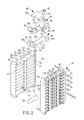
- FIG. 2 is an exploded view of a terminal pole head for a battery pack in accordance with the present invention
- FIG. 3 is a combinational view of the terminal pole head for a battery pack in accordance with the present invention.
- FIG. 4 is a combinational view showing that the terminal pole head for a battery pack in accordance with the present invention is assembled on the battery pack;
- FIG. 5 is a front view showing that the terminal pole head for a battery pack in accordance with the present invention is assembled on the battery pack;
- FIG. 6 is a cross-sectional view showing that the terminal pole head for a battery pack in accordance with the present invention is assembled on the battery pack;
- FIG. 7 is a cross-sectional view showing that the base element is connected to the negative output terminals while the top element is connected to the positive output terminals.
- FIGS. 2-6 show a terminal pole head for a battery pack in accordance with the present invention.
- the battery pack 50 includes plural battery cells 51 that are electrically connected to positive output terminals 53 and negative output terminals 54 through conductive strips 52 .
- the terminal pole head in accordance with the present invention comprises a base element 20 , an isolating element 30 and a top element 40 .
- the base element 20 is a conductive element and includes a main plate 21 .
- the main plate 21 includes a bottom surface 211 and a top surface 212 .
- the main plate further includes an assembling end 22 and an output end 23 that are opposite each other.
- the assembling end 22 is formed with two first connecting plates 24 on two opposite sides of the top surface 212 .
- the two first connecting plates 24 are spaced by a certain distance, so that the two first connecting plates 24 and the top surface 212 can define a space therebetween.
- An outer surface of each of the two first connecting plates 24 is defined as a first connecting portion 241 .
- the output end 23 is formed with two second connecting plates 25 on two opposite sides of the top surface 212 .
- a conductive pin 26 protrudes from the top surface 212 between the two second connecting plates 25 .
- An outer surface of each of the two second connecting plates 25 is defined as a second connecting portion 251 .
- the first connecting portions 241 and the second connecting portions 251 are electrically connected to the positive output terminals 53 through screws 55 .
- the isolating element 30 includes a base plate 31 .
- the base plate 31 includes a first surface 311 and a second surface 312 that are opposite each other.
- the base plate 31 is further formed with an isolating cap 32 and a guide cap 33 .
- the guide cap 33 is formed with a guide hole 331 at an inner side thereof while the isolating cap 32 is formed with a groove 321 at an inner side thereof.
- the isolating element 30 covers the base element 20 .
- the first surface 311 covers the top surface 212 of the base element 20 .
- the isolating cap 32 covers the assembling end 22 only with the first connecting portions 241 exposed.
- the guide cap 33 covers the output end 23 in such a manner that the conductive pin 26 penetrates the guide hole 331 , and only the second connecting portions 251 of the two connecting plates 25 are exposed.
- the top element 40 is a conductive element and formed with a conductive pin 41 protruding from a first end thereof.
- a second end of the top element 40 is formed with a conductive portion 42 .
- the conductive portion 42 is formed with two connecting plates 421 at two opposite sides thereof.
- the top element 40 is disposed on the second surface 312 of the isolating element 30 and isolated from the base element 20 .
- the conductive pin 41 of the top element 40 is located within the groove 321 of the isolating cap 32 while the two connecting plates 421 of the top element are located outside the main plate 21 of the base element 20 .
- the two connecting plates 421 are electrically connected to the negative output terminals 54 of the battery pack 50 .
- FIGS. 2-4 For a better understanding of the present invention, its operation and function, reference should be made to FIGS. 2-4 :
- the positive output terminals 53 will be electrically connected to the first and the second connecting portions 241 , 251 of the base element 20
- the negative output terminals 54 will be electrically connected to the connecting plates 421 of the top element 40 .
- the base element 20 , the isolating element 30 and the top element 40 are assembled one upon another, so that the assembly is easy, and the appearance is smooth after assembly. Further, the base element and the top element are isolated more safely.
- the isolating element 30 covers the main body of the base element 20 with the first and the second connecting portions 241 , 251 exposed only, so that it can avoid the occurrence of short circuit of the base element 20 and the top element 40 .
- the base element 20 can also be electrically connected to the negative output terminals 54 while the top element 40 is electrically connected to the positive output terminals 53 .
- the base element 20 and the top element 40 are formed with the first connecting portions 241 , the second connecting portions 251 , and the connecting plates 421 to be connected to the positive output terminals 53 and the negative output terminals 54 , so that the connecting points in the present invention are scattered, which is quite important for the big power battery pack 50 since it solves the problem of temperature rise caused by excessively high single point resistance.
Abstract
Description
Claims (1)
Priority Applications (1)
| Application Number | Priority Date | Filing Date | Title |
|---|---|---|---|
| US12/943,907 US8409745B2 (en) | 2010-11-10 | 2010-11-10 | Terminal pole head for a battery pack |
Applications Claiming Priority (1)
| Application Number | Priority Date | Filing Date | Title |
|---|---|---|---|
| US12/943,907 US8409745B2 (en) | 2010-11-10 | 2010-11-10 | Terminal pole head for a battery pack |
Publications (2)
| Publication Number | Publication Date |
|---|---|
| US20120115006A1 US20120115006A1 (en) | 2012-05-10 |
| US8409745B2 true US8409745B2 (en) | 2013-04-02 |
Family
ID=46019924
Family Applications (1)
| Application Number | Title | Priority Date | Filing Date |
|---|---|---|---|
| US12/943,907 Active 2031-12-06 US8409745B2 (en) | 2010-11-10 | 2010-11-10 | Terminal pole head for a battery pack |
Country Status (1)
| Country | Link |
|---|---|
| US (1) | US8409745B2 (en) |
Cited By (1)
| Publication number | Priority date | Publication date | Assignee | Title |
|---|---|---|---|---|
| US20130178091A1 (en) * | 2009-09-07 | 2013-07-11 | Yazaki Corporation | Busbar module and power supply unit including same busbar module |
Citations (6)
| Publication number | Priority date | Publication date | Assignee | Title |
|---|---|---|---|---|
| US5977746A (en) * | 1998-07-21 | 1999-11-02 | Stryker Corporation | Rechargeable battery pack and method for manufacturing same |
| US6410185B1 (en) * | 1999-02-15 | 2002-06-25 | Sony Corporation | Battery device for loading on moving body |
| US6428925B1 (en) * | 1999-03-12 | 2002-08-06 | Toshiba Battery Co., Ltd. | Battery pack comprising hollow portion and power tool using the same |
| US7609028B2 (en) * | 2004-12-24 | 2009-10-27 | Lg Chem, Ltd. | Sensing board assembly for secondary battery module |
| US7659029B2 (en) * | 2004-10-26 | 2010-02-09 | Nissan Motor Co., Ltd. | Battery module with insulating plates nipping electrode tabs |
| US7887943B2 (en) * | 2004-11-18 | 2011-02-15 | Sanyo Electric Co., Ltd. | Power device coupling a plurality of cells |
-
2010
- 2010-11-10 US US12/943,907 patent/US8409745B2/en active Active
Patent Citations (6)
| Publication number | Priority date | Publication date | Assignee | Title |
|---|---|---|---|---|
| US5977746A (en) * | 1998-07-21 | 1999-11-02 | Stryker Corporation | Rechargeable battery pack and method for manufacturing same |
| US6410185B1 (en) * | 1999-02-15 | 2002-06-25 | Sony Corporation | Battery device for loading on moving body |
| US6428925B1 (en) * | 1999-03-12 | 2002-08-06 | Toshiba Battery Co., Ltd. | Battery pack comprising hollow portion and power tool using the same |
| US7659029B2 (en) * | 2004-10-26 | 2010-02-09 | Nissan Motor Co., Ltd. | Battery module with insulating plates nipping electrode tabs |
| US7887943B2 (en) * | 2004-11-18 | 2011-02-15 | Sanyo Electric Co., Ltd. | Power device coupling a plurality of cells |
| US7609028B2 (en) * | 2004-12-24 | 2009-10-27 | Lg Chem, Ltd. | Sensing board assembly for secondary battery module |
Cited By (2)
| Publication number | Priority date | Publication date | Assignee | Title |
|---|---|---|---|---|
| US20130178091A1 (en) * | 2009-09-07 | 2013-07-11 | Yazaki Corporation | Busbar module and power supply unit including same busbar module |
| US9039454B2 (en) * | 2009-09-07 | 2015-05-26 | Yazaki Corporation | Busbar module and power supply unit including same busbar module |
Also Published As
| Publication number | Publication date |
|---|---|
| US20120115006A1 (en) | 2012-05-10 |
Similar Documents
| Publication | Publication Date | Title |
|---|---|---|
| KR102233776B1 (en) | Battery module | |
| KR102247392B1 (en) | Battery module | |
| KR20190071454A (en) | Battery Module Having Bus bar Assembly | |
| JP5502760B2 (en) | Battery with multiple individual cells | |
| EP2999045A1 (en) | Battery assembly | |
| ATE550793T1 (en) | RECHARGEABLE BATTERY | |
| JPWO2012101728A1 (en) | Battery module and assembled battery used therefor | |
| KR101912963B1 (en) | Electrical storage element | |
| CA2593944A1 (en) | Fuel cell stack | |
| CN104882572A (en) | Rechargeable battery | |
| KR20120119056A (en) | Substrate for sensing battery cell | |
| US20160260947A1 (en) | Battery pack | |
| US20130323538A1 (en) | Battery unit and electrical device | |
| US11843128B2 (en) | Cell module | |
| GB2482324A (en) | Battery assembly formed by plural soft packing secondary batteries. | |
| EP2940757A1 (en) | Battery module and battery pack | |
| US8409745B2 (en) | Terminal pole head for a battery pack | |
| JP2010238516A (en) | Battery module | |
| JP6135083B2 (en) | Battery module and battery module insulation inspection method | |
| GB2485382A (en) | Terminal Pole Head for a Battery Pack | |
| JP6244648B2 (en) | Electricity storage element | |
| JP5878564B2 (en) | Battery unit | |
| JP2013143192A (en) | Battery unit | |
| JP5670270B2 (en) | Battery unit | |
| US9525162B2 (en) | Secondary battery |
Legal Events
| Date | Code | Title | Description |
|---|---|---|---|
| AS | Assignment |
Owner name: ENERGY CONTROL LIMITED, VIRGIN ISLANDS, BRITISH Free format text: ASSIGNMENT OF ASSIGNORS INTEREST;ASSIGNOR:WU, DONALD P.H.;REEL/FRAME:025347/0090 Effective date: 20101110 |
|
| STCF | Information on status: patent grant |
Free format text: PATENTED CASE |
|
| AS | Assignment |
Owner name: PIHSIANG ENERGY TECHNOLOGY CO.,LTD., TAIWAN Free format text: ASSIGNMENT OF ASSIGNORS INTEREST;ASSIGNOR:ENERGY CONTROL LIMITED;REEL/FRAME:040204/0013 Effective date: 20161031 |
|
| REMI | Maintenance fee reminder mailed | ||
| FPAY | Fee payment |
Year of fee payment: 4 |
|
| SULP | Surcharge for late payment | ||
| FEPP | Fee payment procedure |
Free format text: MAINTENANCE FEE REMINDER MAILED (ORIGINAL EVENT CODE: REM.); ENTITY STATUS OF PATENT OWNER: SMALL ENTITY |
|
| FEPP | Fee payment procedure |
Free format text: 7.5 YR SURCHARGE - LATE PMT W/IN 6 MO, SMALL ENTITY (ORIGINAL EVENT CODE: M2555); ENTITY STATUS OF PATENT OWNER: SMALL ENTITY |
|
| MAFP | Maintenance fee payment |
Free format text: PAYMENT OF MAINTENANCE FEE, 8TH YR, SMALL ENTITY (ORIGINAL EVENT CODE: M2552); ENTITY STATUS OF PATENT OWNER: SMALL ENTITY Year of fee payment: 8 |