US8345285B2 - Displaying jobs in priority order with elapsed time on information processing apparatus - Google Patents
Displaying jobs in priority order with elapsed time on information processing apparatus Download PDFInfo
- Publication number
- US8345285B2 US8345285B2 US12/359,948 US35994809A US8345285B2 US 8345285 B2 US8345285 B2 US 8345285B2 US 35994809 A US35994809 A US 35994809A US 8345285 B2 US8345285 B2 US 8345285B2
- Authority
- US
- United States
- Prior art keywords
- job
- screen
- information
- processing conditions
- order
- Prior art date
- Legal status (The legal status is an assumption and is not a legal conclusion. Google has not performed a legal analysis and makes no representation as to the accuracy of the status listed.)
- Expired - Fee Related, expires
Links
- 230000010365 information processing Effects 0.000 title claims abstract description 26
- 238000012545 processing Methods 0.000 claims abstract description 92
- 238000000034 method Methods 0.000 claims description 40
- 238000003672 processing method Methods 0.000 claims description 5
- 230000005540 biological transmission Effects 0.000 description 80
- 230000008859 change Effects 0.000 description 60
- 230000002093 peripheral effect Effects 0.000 description 44
- 238000010586 diagram Methods 0.000 description 42
- 230000006870 function Effects 0.000 description 28
- 230000008569 process Effects 0.000 description 21
- 230000004044 response Effects 0.000 description 19
- 238000003825 pressing Methods 0.000 description 8
- 238000012546 transfer Methods 0.000 description 5
- 230000009467 reduction Effects 0.000 description 4
- 230000007704 transition Effects 0.000 description 3
- 238000006243 chemical reaction Methods 0.000 description 2
- 238000004891 communication Methods 0.000 description 2
- 238000012795 verification Methods 0.000 description 2
- 241000238876 Acari Species 0.000 description 1
- 238000007792 addition Methods 0.000 description 1
- 238000004458 analytical method Methods 0.000 description 1
- 238000004140 cleaning Methods 0.000 description 1
- 230000006835 compression Effects 0.000 description 1
- 238000007906 compression Methods 0.000 description 1
- 238000007796 conventional method Methods 0.000 description 1
- 238000012937 correction Methods 0.000 description 1
- 238000001514 detection method Methods 0.000 description 1
- 238000011161 development Methods 0.000 description 1
- 238000003702 image correction Methods 0.000 description 1
- 239000004973 liquid crystal related substance Substances 0.000 description 1
- 230000007246 mechanism Effects 0.000 description 1
- 238000012986 modification Methods 0.000 description 1
- 230000004048 modification Effects 0.000 description 1
- 230000003287 optical effect Effects 0.000 description 1
- 108091008695 photoreceptors Proteins 0.000 description 1
- 238000000926 separation method Methods 0.000 description 1
- 210000003462 vein Anatomy 0.000 description 1
Images


Classifications
-
- H—ELECTRICITY
- H04—ELECTRIC COMMUNICATION TECHNIQUE
- H04N—PICTORIAL COMMUNICATION, e.g. TELEVISION
- H04N1/00—Scanning, transmission or reproduction of documents or the like, e.g. facsimile transmission; Details thereof
- H04N1/0035—User-machine interface; Control console
- H04N1/00405—Output means
- H04N1/00408—Display of information to the user, e.g. menus
- H04N1/00413—Display of information to the user, e.g. menus using menus, i.e. presenting the user with a plurality of selectable options
- H04N1/00416—Multi-level menus
- H04N1/00419—Arrangements for navigating between pages or parts of the menu
- H04N1/00427—Arrangements for navigating between pages or parts of the menu using a menu list
-
- G—PHYSICS
- G03—PHOTOGRAPHY; CINEMATOGRAPHY; ANALOGOUS TECHNIQUES USING WAVES OTHER THAN OPTICAL WAVES; ELECTROGRAPHY; HOLOGRAPHY
- G03G—ELECTROGRAPHY; ELECTROPHOTOGRAPHY; MAGNETOGRAPHY
- G03G15/00—Apparatus for electrographic processes using a charge pattern
- G03G15/50—Machine control of apparatus for electrographic processes using a charge pattern, e.g. regulating differents parts of the machine, multimode copiers, microprocessor control
- G03G15/5016—User-machine interface; Display panels; Control console
- G03G15/502—User-machine interface; Display panels; Control console relating to the structure of the control menu, e.g. pop-up menus, help screens
-
- G—PHYSICS
- G03—PHOTOGRAPHY; CINEMATOGRAPHY; ANALOGOUS TECHNIQUES USING WAVES OTHER THAN OPTICAL WAVES; ELECTROGRAPHY; HOLOGRAPHY
- G03G—ELECTROGRAPHY; ELECTROPHOTOGRAPHY; MAGNETOGRAPHY
- G03G15/00—Apparatus for electrographic processes using a charge pattern
- G03G15/50—Machine control of apparatus for electrographic processes using a charge pattern, e.g. regulating differents parts of the machine, multimode copiers, microprocessor control
- G03G15/5075—Remote control machines, e.g. by a host
- G03G15/5091—Remote control machines, e.g. by a host for user-identification or authorisation
-
- H—ELECTRICITY
- H04—ELECTRIC COMMUNICATION TECHNIQUE
- H04N—PICTORIAL COMMUNICATION, e.g. TELEVISION
- H04N1/00—Scanning, transmission or reproduction of documents or the like, e.g. facsimile transmission; Details thereof
- H04N1/0035—User-machine interface; Control console
- H04N1/00405—Output means
- H04N1/00408—Display of information to the user, e.g. menus
- H04N1/00411—Display of information to the user, e.g. menus the display also being used for user input, e.g. touch screen
-
- H—ELECTRICITY
- H04—ELECTRIC COMMUNICATION TECHNIQUE
- H04N—PICTORIAL COMMUNICATION, e.g. TELEVISION
- H04N1/00—Scanning, transmission or reproduction of documents or the like, e.g. facsimile transmission; Details thereof
- H04N1/0035—User-machine interface; Control console
- H04N1/00405—Output means
- H04N1/00408—Display of information to the user, e.g. menus
- H04N1/00413—Display of information to the user, e.g. menus using menus, i.e. presenting the user with a plurality of selectable options
-
- H—ELECTRICITY
- H04—ELECTRIC COMMUNICATION TECHNIQUE
- H04N—PICTORIAL COMMUNICATION, e.g. TELEVISION
- H04N1/00—Scanning, transmission or reproduction of documents or the like, e.g. facsimile transmission; Details thereof
- H04N1/0035—User-machine interface; Control console
- H04N1/00405—Output means
- H04N1/00474—Output means outputting a plurality of functional options, e.g. scan, copy or print
-
- H—ELECTRICITY
- H04—ELECTRIC COMMUNICATION TECHNIQUE
- H04N—PICTORIAL COMMUNICATION, e.g. TELEVISION
- H04N1/00—Scanning, transmission or reproduction of documents or the like, e.g. facsimile transmission; Details thereof
- H04N1/0035—User-machine interface; Control console
- H04N1/00405—Output means
- H04N1/00482—Output means outputting a plurality of job set-up options, e.g. number of copies, paper size or resolution
-
- H—ELECTRICITY
- H04—ELECTRIC COMMUNICATION TECHNIQUE
- H04N—PICTORIAL COMMUNICATION, e.g. TELEVISION
- H04N1/00—Scanning, transmission or reproduction of documents or the like, e.g. facsimile transmission; Details thereof
- H04N1/00912—Arrangements for controlling a still picture apparatus or components thereof not otherwise provided for
- H04N1/00915—Assigning priority to, or interrupting, a particular operation
-
- H—ELECTRICITY
- H04—ELECTRIC COMMUNICATION TECHNIQUE
- H04N—PICTORIAL COMMUNICATION, e.g. TELEVISION
- H04N1/00—Scanning, transmission or reproduction of documents or the like, e.g. facsimile transmission; Details thereof
- H04N1/00912—Arrangements for controlling a still picture apparatus or components thereof not otherwise provided for
- H04N1/00957—Compiling jobs, e.g. for batch processing
-
- H—ELECTRICITY
- H04—ELECTRIC COMMUNICATION TECHNIQUE
- H04N—PICTORIAL COMMUNICATION, e.g. TELEVISION
- H04N1/00—Scanning, transmission or reproduction of documents or the like, e.g. facsimile transmission; Details thereof
- H04N1/00962—Input arrangements for operating instructions or parameters, e.g. updating internal software
- H04N1/0097—Storage of instructions or parameters, e.g. customised instructions or different parameters for different user IDs
-
- G—PHYSICS
- G03—PHOTOGRAPHY; CINEMATOGRAPHY; ANALOGOUS TECHNIQUES USING WAVES OTHER THAN OPTICAL WAVES; ELECTROGRAPHY; HOLOGRAPHY
- G03G—ELECTROGRAPHY; ELECTROPHOTOGRAPHY; MAGNETOGRAPHY
- G03G2215/00—Apparatus for electrophotographic processes
- G03G2215/00025—Machine control, e.g. regulating different parts of the machine
- G03G2215/00109—Remote control of apparatus, e.g. by a host
-
- H—ELECTRICITY
- H04—ELECTRIC COMMUNICATION TECHNIQUE
- H04N—PICTORIAL COMMUNICATION, e.g. TELEVISION
- H04N1/00—Scanning, transmission or reproduction of documents or the like, e.g. facsimile transmission; Details thereof
- H04N1/00127—Connection or combination of a still picture apparatus with another apparatus, e.g. for storage, processing or transmission of still picture signals or of information associated with a still picture
- H04N1/00204—Connection or combination of a still picture apparatus with another apparatus, e.g. for storage, processing or transmission of still picture signals or of information associated with a still picture with a digital computer or a digital computer system, e.g. an internet server
- H04N1/00209—Transmitting or receiving image data, e.g. facsimile data, via a computer, e.g. using e-mail, a computer network, the internet, I-fax
-
- H—ELECTRICITY
- H04—ELECTRIC COMMUNICATION TECHNIQUE
- H04N—PICTORIAL COMMUNICATION, e.g. TELEVISION
- H04N1/00—Scanning, transmission or reproduction of documents or the like, e.g. facsimile transmission; Details thereof
- H04N1/44—Secrecy systems
- H04N1/4406—Restricting access, e.g. according to user identity
- H04N1/4413—Restricting access, e.g. according to user identity involving the use of passwords, ID codes or the like, e.g. PIN
-
- H—ELECTRICITY
- H04—ELECTRIC COMMUNICATION TECHNIQUE
- H04N—PICTORIAL COMMUNICATION, e.g. TELEVISION
- H04N2201/00—Indexing scheme relating to scanning, transmission or reproduction of documents or the like, and to details thereof
- H04N2201/32—Circuits or arrangements for control or supervision between transmitter and receiver or between image input and image output device, e.g. between a still-image camera and its memory or between a still-image camera and a printer device
- H04N2201/3201—Display, printing, storage or transmission of additional information, e.g. ID code, date and time or title
- H04N2201/3212—Display, printing, storage or transmission of additional information, e.g. ID code, date and time or title of data relating to a job, e.g. communication, capture or filing of an image
- H04N2201/3222—Display, printing, storage or transmission of additional information, e.g. ID code, date and time or title of data relating to a job, e.g. communication, capture or filing of an image of processing required or performed, e.g. forwarding, urgent or confidential handling
-
- H—ELECTRICITY
- H04—ELECTRIC COMMUNICATION TECHNIQUE
- H04N—PICTORIAL COMMUNICATION, e.g. TELEVISION
- H04N2201/00—Indexing scheme relating to scanning, transmission or reproduction of documents or the like, and to details thereof
- H04N2201/32—Circuits or arrangements for control or supervision between transmitter and receiver or between image input and image output device, e.g. between a still-image camera and its memory or between a still-image camera and a printer device
- H04N2201/3201—Display, printing, storage or transmission of additional information, e.g. ID code, date and time or title
- H04N2201/3225—Display, printing, storage or transmission of additional information, e.g. ID code, date and time or title of data relating to an image, a page or a document
- H04N2201/3242—Display, printing, storage or transmission of additional information, e.g. ID code, date and time or title of data relating to an image, a page or a document of processing required or performed, e.g. for reproduction or before recording
Definitions
- the present invention relates to an information processing apparatus and program, particularly to an information processing apparatus having a function of displaying the history of job settings having been executed, and a program for running this information processing apparatus.
- the pattern of usage in each mode for each user often tends to appear.
- series of setting such as “specific density, simplex setting and 2 in 1” is often selected;
- scanning mode “a specific file format (PDF: Portable Document Format (registered trademark)), specific resolution (200 dpi), a specific read-in mode (simplex)” is usually selected;
- a specific transmitter (user A)/IP (Internet Protocol)-FAX/redirected transmission” is often chosen.
- a user tends to select a specific pattern in each mode according to his preference or the purpose of use.
- the multi-functional peripheral requests the user to select a setting every time a mode is used, the user must repeat the same operations for each mode. This will consume user's time and effort. Particularly when each mode contains a great number of functions and alternatives that must be often utilized, this will result in an increased number of items to be set (the number of settings), a deeper hierarchical level of operation in setting, and an increased number of operation screen changes. This leads to complicated operations and time-consuming setting. Thus, if the same complicated operations must be repeated for every use of the multi-functional peripheral function, the user will be exposed to a growing stress. Further, when the user wants to correct a job error after having set or executed it, the user has to repeat the same operations from the very beginning. This will cause a great deal of inconvenience to the user.
- some multi-functional peripheral is provided with the function wherein the settings of the job having been executed (processing conditions) are stored in a nonvolatile memory and the history is displayed in chronological order. From this history, the user selects a desired job, and the settings of that job are reflected on the new job settings.
- this function also allows partial changes, in addition to a direct use of the previous settings. For example, when a user wants to correct a setting error after execution, the user can use the last job setting to correct the error, or can easily create a new job in conformity to correct settings.
- setting can be completed by simple operations in some cases, but in other cases, a user is forced to perform complicated operations due to a greater number of settings, an increased number of the hierarchical operations or a large number of screen changes.
- a user is forced to perform complicated operations due to a greater number of settings, an increased number of the hierarchical operations or a large number of screen changes.
- use of the previous settings leads to a substantial simplification of the operation and more effective setting.
- the technique disclosed in the Japanese Unexamined Patent Application Publication No. 2005-25656 displays the menu screen wherein the last operation was performed in response to the user's last access.
- This menu screen is not always the optimum screen for the current setting. Further, since the structure is not designed to use the previous settings, setting operation must be performed independently of the menu screen displayed at the time of new access.
- the object of the present invention is to solve the aforementioned problems and to provide an information processing apparatus and program wherein, when the job processing conditions are to be re-set using the previous settings, display can be made to meet the user's requirements, with sufficient consideration given to the operation items and elapsed time.
- One aspects of the present invention are any one of the image forming apparatus described as follows.
- An information processing apparatus including:
- an operation display section for displaying a screen to set processing conditions relating to a job and for receiving an operation to set the processing conditions relating to the job;
- a generation section for generating a job under the processing conditions set by the operation with the operation display section
- a storage section for storing job information including the processing conditions relating to the job generated by the generation section;
- a measuring section for measuring an elapsed time from a time when the job is generated by the generation section
- control section which displays a plurality of previously generated jobs in a predetermined order using the job information on the operation display section, and replaces an order of the plurality of the jobs based on contents of the operation display section when the processing conditions is set and the elapsed time during displaying.
- Another aspect of the present invention is a computer readable recording medium described as follows.
- a computer readable recording medium storing a program which causes an information processing apparatus including an operation display section and a storage section, executes a method including:
- FIG. 1 is a block diagram showing the system configuration of the image forming system (information processing system) in the embodiment of the present invention
- FIG. 2 is a block diagram showing the schematic structure of the multi-functional peripheral as an image forming apparatus (information processing apparatus) in the embodiment of the present invention
- FIG. 3 is an explanatory diagram showing the changes of operation screens displayed on the operation display section in the process of setting the [2 in 1] printing job;
- FIG. 4 is an explanatory diagram showing the changes of the operation screens displayed on the operation display section in the process of setting the [NON IMAGE AREA ERASING] printing job;
- FIG. 5 is an explanatory diagram showing the changes of the operation screens displayed on the operation display section in the process of setting the [2 in 1] [text/photo] [binding margin] printing job;
- FIG. 6 is an explanatory diagram showing the changes of the operation screens displayed on the operation display section in the process of setting the [Scan to SMB] transmission job;
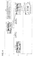
- FIG. 7 is an explanatory diagram showing the changes of the operation screens displayed on the operation display section in the process of setting the [Scan to SMB] broadcast transmission job;
- FIG. 8(A) is an explanatory diagram showing the enlarged view of scan top screen in the operation screen of FIG. 7 ;
- FIG. 8(B) is an explanatory diagram showing the enlarged view of direct input screen in the operation screen of FIG. 7 ;
- FIG. 8(C) is an explanatory diagram showing the enlarged view of file transmission (SMB) screen in the operation screen of FIG. 7 ;
- FIG. 9(D) is an explanatory diagram showing the enlarged view of host name screen in the operation screen of FIG. 7 ;
- FIG. 9(E) is an explanatory diagram showing the enlarged view of file transmission (SMB) screen in the operation screen of FIG. 7 ;
- FIG. 9(F) is an explanatory diagram showing the enlarged view of file path screen in the operation screen of FIG. 7 ;
- FIG. 10(G) is an explanatory diagram showing the enlarged view of file transmission (SMB) screen in the operation screen of FIG. 7 ;
- FIG. 10(H) is an explanatory diagram showing the enlarged view of user name screen in the operation screen of FIG. 7 ;
- FIG. 10(I) is an explanatory diagram showing the enlarged view of file transmission (SMB) screen in the operation screen of FIG. 7 ;
- FIG. 11(J) is an explanatory diagram showing the enlarged view of password screen in the operation screen of FIG. 7 ;
- FIG. 11(K) is an explanatory diagram showing the enlarged view of file transmission (SMB) screen in the operation screen of FIG. 7 ;
- FIG. 11(L) is an explanatory diagram showing the enlarged view of direct input screen in the operation screen of FIG. 7 ;
- FIG. 12(M) is an explanatory diagram showing the enlarged view of file transmission (SMB) screen in the operation screen of FIG. 7 ;
- FIG. 12(N) is an explanatory diagram showing the enlarged view of host name screen in the operation screen of FIG. 7 ;
- FIG. 12(O) is an explanatory diagram showing the enlarged view of file transmission (SMB) screen in the operation screen of FIG. 7 ;
- FIG. 13(P) is an explanatory diagram showing the enlarged view of file path screen in the operation screen of FIG. 7 ;
- FIG. 13(Q) is an explanatory diagram showing the enlarged view of file transmission (SMB) screen in the operation screen of FIG. 7 ;
- FIG. 13(R) is an explanatory diagram showing the enlarged view of user name screen in the operation screen of FIG. 7 ;
- FIG. 14(S) is an explanatory diagram showing the enlarged view of password screen in the operation screen of FIG. 7 ;
- FIG. 14(T) is an explanatory diagram showing the enlarged view of file transmission (SMB) screen in the operation screen of FIG. 7 ;
- FIG. 14(U) is an explanatory diagram showing the enlarged view of direct input screen in the operation screen of FIG. 7 ;
- FIG. 15 is a diagram representing an example of the configuration of a job history table
- FIG. 16 is an explanatory diagram showing the display screen for calculation of the correlation number displayed on the operation display section immediately after the latest job execution;
- FIG. 17 is an explanatory diagram showing the display screen for calculation of the correlation number displayed on the operation display section 6 hours after the latest job execution;
- FIG. 18 is a diagram representing an example of the result of calculating the correlation number
- FIG. 19 is a diagram graphically representing the relationship between the elapsed time and correlation number (theoretical history value) of the job using the result of calculation in FIG. 18 ;
- FIGS. 20(A) and (B) are explanatory diagrams showing the changes of the display screen of the job history shown in the operation display section;
- FIGS. 21(A) and (B) are explanatory diagrams showing the overall image of the correspondence between the changes of the job history display screen of FIG. 20 and the elapsed time of the job;
- FIG. 22 is an explanatory diagram showing the changes of screens when the job number is selected on the history display screen of FIG. 20(A) ;
- FIG. 23 is an explanatory diagram showing the changes of screens when the setting is selected on the history display screen of FIG. 20(B) ;
- FIG. 24 is a flow diagram showing the process of operation registration performed by the multi-functional peripheral in the embodiment of the present invention.
- FIG. 25 is a flow diagram showing the process of job history display performed by the multi-functional peripheral in the embodiment of the present invention.
- FIG. 26 is a flow diagram showing the process of calculating the correlation number by the multi-functional peripheral in the embodiment of the present invention.
- FIG. 1 shows an example of the system configuration of the image forming system (information processing system) 5 in the embodiment of the present invention.
- the image forming system 5 connects a desired number of terminals 10 and the multi-functional peripheral (MFP: Multi Function Peripheral/Multi Function Printer) 20 as an image forming apparatus (information processing apparatus) accessed from each terminal 10 via the network 2 such as LAN (Local Area Network).
- the multi-functional peripheral 20 is provided with a document copying function, printing function, scanning function, faxing function, boxing function, and file transfer function (SMB (Server Message Block) transfer function).
- SMB Server Message Block
- the terminal 10 accesses the multi-functional peripheral 20 via the network 2 , and requests various jobs such as a printing job and various operations to be executed.
- the terminal 10 is made up of the driver program and others of the multi-functional peripheral 20 incorporated into a personal computer.
- FIG. 2 shows the schematic configuration of the multi-functional peripheral 20 .
- the multi-functional peripheral 20 is composed of a CPU (Central Processing Unit) 21 as a controller which is connected with a ROM (Read Only Memory) 23 , RAM (Random Access Memory) 24 , nonvolatile memory 25 , operation display section 26 , communication section 27 , image conversion section 28 , reading section 29 , printer 30 , clock 31 and authentication section 32 via a bus 22 .
- ROM Read Only Memory
- RAM Random Access Memory
- the CPU 21 controls the operation of the multi-functional peripheral 20 in conformity to the program stored into the ROM 23 .
- the RAM 24 is used as the work memory for temporarily storing various forms of data when a program is executed by the CPU 21 . Further, the RAM 24 is also used as an image memory to store the image data.
- the nonvolatile memory 25 retains the memory even after the power source has been turned off.
- the nonvolatile memory 25 stores the job history table 40 ( FIG. 15 ) to be described later, setting information (coefficient) used to calculate the correlation number, screen data displayed on the operation display section 26 , transition table and user authentication information.
- the operation display section 26 performs the functions of displaying various forms of operation screens and guide screens for a user, and receiving various forms of operations from the user.
- the operation display section 26 includes a liquid crystal display, touch panel mounted on the screen thereof, start key (execution key), history verification key, cancel key, end key and various types of switches.
- the communication section 27 performs the function of communicating with an external apparatus such as the terminal 10 via the network 2 .
- the reading section 29 optically reads a document and acquires image data.
- the reading section 29 is composed, for example, of a light source for illuminating a document, an image sensor for receiving light reflected from the document and reading one line of the document across the width, a scanning mechanism for moving the moving the position ready by the image sensor in units of line along the length of the document, and an optical path made up of lenses and mirrors for leading the light reflected from the document, to the image sensor.
- the image conversion section 28 applies various forms of image processing to image data, image processing including image correction, rotation, enlargement/reduction and compression/elongation.
- the printer 30 prints out the image corresponding to the inputted image data on recording paper and outputs it.
- the printer 30 can be formed as a laser printer, for example, provided with a recording paper conveyance apparatus, photoreceptor drum, charging device, laser unit, development apparatus, transfer/separation apparatus, cleaning apparatus, and fixing apparatus, whereby an image is formed on recording paper by electrophotographic process.
- the clock 31 ticks away the time.
- the authentication section 32 acquires the authentication data and authenticates a user based on the pre-registered authentication information.
- This user authentication is performed by various forms of general-purpose authentication techniques which are used independently or in combination.
- Such techniques include the card authentication technique wherein personal authentication is performed, for example, by reading the authentication data stored in the IC (Integrated Circuit) card or ID (Identification) card and checking it against the pre-registered authentication information; and the biological authentication technique wherein personal authentication is performed by reading the biological information such as fingerprints and finger vein as authentication data and checking it against the pre-registered authentication information.
- the CPU 21 serves the functions of a generation device for executing the program to generate a job under the processing conditions set by the operation on the operation display section 26 ; a measuring device for measuring the time elapsed from the generation of a job by obtaining time information from the clock 31 ; and a control device for displaying on the operation display section 26 the operation screen for setting the job processing conditions, and the history of the job having been executed. Further, the CPU 21 also serves the function of calculating the correlation number to be described later for the purpose of replacing the order of a plurality of jobs in history display.
- the multi-functional peripheral 20 has a plurality of types of modes such as copying mode, scanning mode and file transfer mode. Each mode is provided with a plurality of functions (alternatives). To permit setting of the jobs in a great number of variations based on these types of modes and functions, the multi-functional peripheral 20 is provided with a plurality of operation screens, which are displayed by selecting the operation display section 26 .
- the operation screen displayed on the operation display section 26 displays the buttons and icons for changing the screens, selecting and setting the job processing conditions and various forms of modes and functions.
- the multi-functional peripheral 20 changes the screens and sets the jobs.
- the multi-functional peripheral 20 is equipped with a plurality of hierarchical levels of operations. For example, when the user wants to perform the settings wherein the same modes or functions are associated, or to perform the settings under detailed processing conditions, the screens are changed and the operations proceed in the hierarchical direction at the same time so that the user can easily the direction in which the operations should proceed in order to perform desired settings, or the context of the current operations.
- the aforementioned change of the screens is performed with reference to the screen data stored in the nonvolatile memory 25 and the screen change table (tree diagram).
- the multi-functional peripheral 20 displays the history of the previously set/executed jobs on the operation display section 26 in a predetermined order.
- the operation screens are changed.
- the change of operation screens is accompanied by the change of the hierarchical levels of operation, whereby the positions to be set are reached.
- the job setting processes the number of hierarchical levels of operations, number of settings and the number of screen changes, to put it more specifically—vary according to the processing conditions of the job to be set.
- more complicated operation items i.e., the operations items having a greater number of hierarchical levels of operations, a greater number of settings and a greater number of screen changes—are assigned with a higher order of importance.
- the following describes the details of the operation items when a job is set on the operation display section 26 —i.e., the hierarchical level of operation (layer), setting (setup) and screen change (operation panel transition).
- FIG. 3 through FIG. 7 provide a schematic representation (tree structure) of the changes of the operation screens displayed on the operation display section 26 in the process of setting the copying job or file transfer (SMB transmission) job.
- This example has four operation hierarchical levels (L1 through L4) ranging from the first hierarchical level as the top level to the fourth hierarchical level as the bottom level.
- the top screen (initial screen) provided on the first hierarchical level L1 is displayed on the operation display section 26 .
- the operations (pressing of the button) on the operation screen displayed on the operation display section 26 includes (1) screen switching operation, (2) job setting (job generation) operation, and (3) operation related to both of them (i.e., simultaneous job setting and screen change). In this example, only the operations (2) and (3) are counted as the number of settings.
- the user X of the multi-functional peripheral 20 undergoes user authentication at desired time points, and performs the setting of five types of jobs.
- FIG. 3 shows the operation screen, hierarchical level of operation and setting position in the process of setting the first job.
- the setting of the first job is related to the [2 in 1] printing.
- the CPU 21 switches the display on the operation display section 26 over to the MULTI IN ONE/document screen 52 provided on the second hierarchical level L2 (screen change: arrow mark T 1 ).
- the CPU 21 sets the [2 in 1] (setting position: S 1 ).
- the multi-functional peripheral 20 is ready to take a copy.
- the CPU 21 verifies the details of the settings, and generates and executes the [2 in 1] printing job.
- the operation items in this case include two hierarchical levels, one settings and one screen change.
- FIG. 4 shows the operation screen, hierarchical level of operation and setting position in the process of setting the second job.
- the second job setting item includes the [NON IMAGE AREA ERASING] printing.
- the CPU 21 switches the display of the operation display section 26 to the applied setting screen 53 on the second hierarchical level L2 (screen change: arrow mark T 1 ). If the erasure button 64 displayed on the applied setting screen 53 has been pressed, the CPU 21 switches the display of the operation display section 26 over to the erasure screen 54 on the third hierarchical level L3 (screen change: arrow mark T 2 ).
- the CPU 21 sets the [NON IMAGE AREA ERASING] (setting position: S 1 ). If the OK button 66 has been pressed, the CPU 21 switches the display of the operation display section 26 over to the applied setting screen 53 on the second hierarchical level L2 (screen change: arrow mark T 3 ).
- the multi-functional peripheral 20 is ready to take a copy.
- the CPU 21 verifies the details of the settings, and generates and executes the [NON IMAGE AREA ERASING] printing job.
- the operation items in this case include three hierarchical levels, one settings and three screen changes.
- FIG. 5 shows the operation screen, hierarchical level of operation and setting position in the process of setting the third job.
- the setting of the third job is related to the [2 in 1] [text/photo] [binding margin] printing.
- the CPU 21 sets the [2 in 1] (screen change: arrow mark T 1 /setting position: S 1 ).
- the CPU 21 switches the display of the operation display section 26 over to the document image quality screen 55 (screen change: arrow mark T 2 ) on the same second hierarchical level L2 as that of the MULTI IN ONE/document screen 52 .
- the CPU 21 sets the [text/photo] (setting position: S 2 ).
- the CPU 21 switches the display of the operation display section 26 over to the applied setting screen 53 on the same second hierarchical level L2 (screen change: arrow mark T 3 )
- the binding margin button 69 shown as “binding margin” in the drawing
- the CPU 21 switches the display of the operation display section 26 over to the binding margin creation screen 56 on the third hierarchical level L3 (shown as “binding margin CREATE” in the drawing) (screen change: arrow mark T 4 ).
- the CPU 21 sets the [binding margin] when the OK button 66 has been pressed (setting position: S 4 ), and switches the display of the operation display section 26 over to the applied setting screen 53 on the second hierarchical level L2 (screen change: arrow mark T 5 ).
- the multi-functional peripheral 20 is ready to take a copy.
- the CPU 21 verifies the details of the settings, and generates and executes the [2 in 1] [text/photo] [binding margin] printing job.
- the operation items in this case include three hierarchical levels, four settings and five screen changes.
- FIG. 6 shows the operation screen, hierarchical level of operation and setting position in the process for setting the fourth job.
- the setting of the fourth job is related to the [Scan to SMB] transmission.
- the CPU 21 switches the display of the operation display section 26 over to the direct input screen 72 on the second hierarchical level L2 (screen change: arrow mark T 1 )
- the file transmission (SMB) button 82 displayed on the direct input screen 72 has been pressed, (setting position: S 1 )
- the CPU 21 switches the display of the operation display section 26 over to the file transmission (SMB) screen 73 on the third hierarchical level L3 (screen change: arrow mark T 2 ).
- the CPU 21 switches the display of the operation display section 26 over to the host name screen 74 on the fourth hierarchical level L4 (screen change: arrow mark T 3 ).
- the OK button 87 has been pressed on the host name screen 74 in response to the input of the host name (IP address) of the destination, the CPU 21 sets the host name (setting position: S 2 ), and switches the display of the operation display section 26 over to the file transmission (SMB) screen 73 of the third hierarchical level L3 (screen change: arrow mark T 4 ).
- the CPU 21 switches the display of the operation display section 26 over to the file path (group name) screen 75 on the fourth hierarchical level L4 (screen change: arrow mark T 5 ).
- the OK button 87 has been pressed on the file path screen 75 in response to the input of the file path (group name) of the destination, the CPU 21 sets the file path (group name) (setting position: S 3 ), and switches the display of the operation display section 26 over to the file transmission (SMB) screen 73 of the third hierarchical level L3 (screen change: arrow mark T 6 ).
- the CPU 21 switches the display of the operation display section 26 over to the user name screen 76 of the fourth hierarchical level L4 (screen change: arrow mark T 7 ).
- the OK button 87 has been pressed on the user name screen 76 in response to the input of the user name on the destination, the CPU 21 sets the user name (setting position: S 4 ), and switches the display of the operation display section 26 over to the file transmission (SMB) screen 73 of the third hierarchical level L3 (screen change: arrow mark T 8 ).
- the CPU 21 switches the display of the operation display section 26 over to the password screen 77 on the fourth hierarchical level L4 (screen change: arrow mark T 9 ).
- the OK button 87 has been pressed on the password screen 77 in response to the input of the password set on the destination, the CPU 21 sets the password (setting position: S 5 ), and switches the display of the operation display section 26 over to the file transmission (SMB) screen 73 on the third hierarchical level L3 (screen change: arrow mark T 10 ).
- the CPU 21 switches the display of the operation display section 26 over to the direct input screen 72 of the second hierarchical level L2 (screen change: arrow mark T 11 ).
- the CPU 21 verifies the details of the setting and generates and executes the [Scan to SMB] transmission job.
- the operation items include four hierarchical levels, five settings and 11 screen changes.
- FIG. 7 shows the operation screen, hierarchical level of operation and setting position in the process of setting the fifth job.
- FIG. 8 through FIG. 14 show an enlarged view of each operation screen of FIG. 7 .
- the setting items of the fifth job include the [Scan to SMB] broadcast transmission.
- the [Scan to SMB] broadcast transmission of the fifth job sets the information of destination of the file transmission (host name, file path (group name), user name and password) having been described with reference to the [Scan to SMB] transmission of the fourth job, for the a plurality of destination of the file transmission (broadcasting address) to which broadcast transmission is to be made. Except for the aforementioned procedure, the same operations items as those of the [Scan to SMB] transmission of the fourth job are set. The following describes the operation items for setting the [Scan to SMB] broadcast transmission in conformity to the flow of the operation screens of FIG. 8 through FIG. 14 :
- FIG. 8(A) shows an enlarged view of the scan top screen 71 on the first hierarchical level L1 of FIG. 7 .
- the CPU 21 switches the display of the operation display section 26 over to the direct input screen 72 of FIG. 8(B) (direct input screen 72 of the second hierarchical level L2 of FIG. 7 /screen change: arrow mark T 1 ).
- the file transmission (SMB) button 82 of the direct input screen 72 has been pressed (setting position: S 1 in FIG. 7 )
- the CPU 21 switches the display of the operation display section 26 over to the file transmission (SMB) screen 73 of FIG. 8(C) (file transmission (SMB) screen 73 of the third hierarchical level L3 of FIG. 7 /screen change: arrow mark T 2 ).
- the CPU 21 switches the display of the operation display section 26 over to the host name screen 74 of FIG. 9(D) (the host name screen 74 of the fourth hierarchical level L4 of FIG. 7 /screen change: arrow mark T 3 ).
- the OK button 87 has been pressed on the host name screen 74 in response to the input of the host name (IP address) on the destination, the CPU 21 sets the host name (setting position: S 2 in FIG. 2 ), and switches the display of the operation display section 26 over to the file transmission (SMB) screen 73 of FIG. 9(E) (file transmission (SMB) screen 73 of the third hierarchical level L3 of FIG. 7 /screen change: arrow mark T 4 ).
- the CPU 21 switches the display of the operation display section 26 over to the file path screen 75 of FIG. 9(F) (file path screen 75 of the fourth hierarchical level L4 of FIG. 7 /screen change: arrow mark T 5 ).
- the OK button 87 has been pressed on the file path screen 75 in response to the input of the file path on the destination, the CPU 21 sets the file path (setting position: S 3 in FIG. 7 ), and switches the display of the operation display section 26 over to the file transmission (SMB) screen 73 of FIG. 10(G) (file transmission (SMB) screen 73 of the third hierarchical level L3 of FIG. 7 /screen change: arrow mark T 6 ).
- the CPU 21 switches the display of the operation display section 26 over to the user name screen 76 of FIG. 10(H) (user name screen 76 of the fourth hierarchical level L4 of FIG. 7 /screen change: arrow mark T 7 ).
- the OK button 87 has been pressed on the user name screen 76 in response to the input of the user name on the destination, the CPU 21 sets the user name (setting position: S 4 in FIG. 7 ), and switches the display of the operation display section 26 over to the file transmission (SMB) screen 73 of FIG. 10(I) (file transmission (SMB) screen 73 of the third hierarchical level L3 of FIG. 7 /screen change: arrow mark T 8 ).
- the CPU 21 switches the display of the operation display section 26 over to the password screen 7 of FIG. 11(J) (password screen 77 of the fourth hierarchical level L4 of FIG. 7 /screen change: arrow mark T 9 ).
- the OK button 87 has been pressed on the password screen 77 in response to the input of the password set on the destination, the CPU 21 sets the password (setting position: S 5 in FIG. 7 ), and switches the display of the operation display section 26 over to the file transmission (SMB) screen 73 of FIG. 11(K) (file transmission (SMB) screen 73 of the third hierarchical level L3 of FIG. 7 /screen change: arrow mark T 10 ).
- the CPU 21 verifies the contents of the information set on the destination of the file transmission of the first user, and switches the display of the operation display section 26 over to the direct input screen 72 of FIG. 11(L) (direct input screen 72 of the second hierarchical level L2 of FIG. 7 /screen change: arrow mark T 11 ).
- the direct input screen 72 of FIG. 11(L) direct input screen 72 of the second hierarchical level L2 of FIG. 7 /screen change: arrow mark T 11 .
- information on the destination of the file transmission of the first user having been set this time appears in the “broadcast address list” on the direct input screen 72 .
- the CPU 21 switches the display of the operation display section 26 over to the host name screen 74 of FIG. 12(N) (host name screen 74 of the fourth hierarchical level L4 of FIG. 7 /screen change: arrow mark T 13 ).
- the OK button 87 has been pressed on the host name screen 74 in response to the input of the host name (IP address) on the destination, the CPU 21 sets the host name (setting position: S 7 in FIG. 7 ), and switches the display of the operation display section 26 over to the file transmission (SMB) screen 73 of FIG. 12 ( 0 ) (file transmission (SMB) screen 73 of the third hierarchical level L3 of FIG. 7 /screen change: arrow mark T 14 )
- the CPU 21 switches the display of the operation display section 26 over to the file path screen 75 of FIG. 13(P) (file path screen 75 of the fourth hierarchical level L4 of FIG. 7 /screen change: arrow mark T 15 ).
- the OK button 87 has been pressed on the file path screen 75 in response to the input of the file path on the destination, the CPU 21 sets the file path (setting position: S 8 in FIG. 7 ), and switches the display of the operation display section 26 over to the file transmission (SMB) screen 73 of FIG. 13(Q) (file transmission (SMB) screen 73 of the third hierarchical level L3 of FIG. 7 )/screen change: arrow mark T 16 ).
- the CPU 21 switches the display of the operation display section 26 over to the user name screen 76 of FIG. 13(R) (user name screen 76 of the fourth hierarchical level L4 of FIG. 7 /screen change: arrow mark T 17 ).
- the OK button 87 has been pressed on the user name screen 76 in response to the input of the user name on the destination, the CPU 21 sets the user name (setting position: S 9 in FIG. 7 ), and switches the display of the operation display section 26 over to the file transmission (SMB) screen 73 (file transmission (SMB) screen 73 of the third hierarchical level L3 of FIG. 7 /screen change: arrow mark T 18 ).
- the CPU 21 switches the display of the operation display section 26 over to the password screen 77 of FIG. 14(S) (password screen 77 of the fourth hierarchical level L4 of FIG. 7 /screen change: arrow mark T 19 ).
- the OK button 87 has been pressed on the password screen 77 in response to the input of the password set on the destination, the CPU 21 sets the password (setting position: S 10 in FIG. 7 ), and switches the display of the operation display section 26 over to the file transmission (SMB) screen 73 of FIG. 14(T) (file transmission (SMB) screen 73 of the third hierarchical level L3 of FIG. 7 /screen change: arrow mark T 20 ).
- the CPU 21 switches the display of the operation display section 26 over to the direct input screen 72 of the second hierarchical level L2 of FIG. 14(U) (screen change: arrow mark T 21 ). Further, when a destination of the file transmission (broadcast address) is present, information on the destination of the file transmission for the third and later users can be set by the same operation.
- the CPU 21 verifies the settings, and generates and executes [Scan to SMB] broadcast transmission job. When there are two of these broadcast addresses, the operation items include four hierarchical levels, ten settings and 21 screen changes.
- FIG. 15 shows an example of the structure of the job history table 40 stored in the nonvolatile memory 25 by the settings of the aforementioned five jobs.
- the job history table 40 registers the information for displaying the job history. It registers the job execution order data, execution time point (date and time) data, setting description data and operation description data in the form associated with one another. Further, when the user is specified by user authentication, the user name data is also registered in the associated form.
- the execution time point (date and time) data has been obtained by the CPU 21 from the clock 31 at the time of job execution.
- the job execution order data indicates serial numbers automatically assigned by the CPU 21 sequentially starting from the job having the latest execution time point.
- the serial numbers are exemplified by 1 through N starting from 1.
- the setting description data indicates the job settings (processing conditions) determined by the user.
- the operation description data represents the details of the operations performed by the user for job setting. To put it in greater details, this data includes the number-of-hierarchical-levels data showing the number of hierarchical levels of operations in the job setting operation, number-of-settings data showing the number of settings in job setting operation, and the number-of-screen-changes data representing the number of screen changes in the job setting operation.
- the user name data indicates the name of the user having set the job and is exemplified by the user name registered in the form associated with the authentication information.
- the execution time points (date and time) of the aforementioned five jobs are, for example, 17:00, Jun. 25, 2007 for the fifth job, 14:00, Jun. 26, 2007 for the fourth job, 17:00, Jun. 26, 2007 for the third job, 11:00, Jun. 27, 2007 for the second job, and 13:00, Jun. 27, 2007 for the first job.
- the job history table 40 includes the registrations of the jobs from 1 through 5 according to the order of execution, wherein these jobs are arranged sequentially from the first through five jobs, starting from the first job having the latest execution time point (date and time).
- the second job was executed two hours before the first job
- the third job was executed 20 hours before the first job
- the fourth job was executed 23 hours before the first job
- the fifth job was executed 44 hours before the first job.
- the history of a plurality of previously executed (generated) jobs is displayed in a predetermined order on the operation display section 26 using the information registered in the job history table 40 . Further, the order of the jobs whose history is display is changed based on the operation items at the time of job setting and the time elapsed from the time of job execution.
- a change in the order of the jobs having the history thereof displayed is performed in conformity to the order of magnitude of correlation numbers by calculating these correlation numbers for each job, based on the aforementioned operation items and the elapsed time.
- FIG. 16 and FIG. 17 show the display screen for calculating the correlation numbers.
- FIG. 16 shows the correlation number calculation display screen 100 displayed at 13:00, Jun. 27, 2007 immediately after execution of [2 in 1] printing job as the first and latest job.
- FIG. 17 shows the correlation number calculation display screen 101 displayed at 19:00, Jun. 27, 2007 six hours after execution of the latest job.
- These correlation number calculation display screens 100 and 101 are displayed, for example, on the operation display section 26 in response to a predetermined operation on the operation display section 26 .
- the correlation number calculation display screens 100 and 101 indicate the order of job execution, job name (job setting item), correlation number calculation parameter and correlation number.
- the parameters selected freely by the user to calculate the correlation number include those for the number of hierarchical levels, number of settings and the number of screen changes.
- the parameter for elapsed time is provided as the essential parameter.
- the parameters for the number of hierarchical levels, number of settings and the number of screen changes that are selected freely can be separately selected or cancelled, for example, by a predetermined operation on the operation display section 26 .
- the elapsed time provided as an essential parameter denotes the duration of time elapsed from the time of job execution to the current time point when this display screen appears.
- the correlation number calculation display screen 100 of FIG. 16 is displayed immediately after execution of the [2 in 1] printing job as the first job.
- the elapsed time is “0” for first job, “2” for the second job having been executed two hours before the first job, “20” for the third job having been executed 20 hours before the first job, “23” for the fourth job having been executed 23 hours before the first job, and “44” for the fourth job having been executed 44 hours before the first job.
- the correlation number calculation display screen 101 of FIG. 17 appears 6 hours after execution of the [2 in 1] printing job as the first job.
- the elapsed time displayed is “6” for the first job.
- the values obtained by adding “6” to the values shown on the screen 100 of FIG. 16 are displayed as the elapsed times, respectively.
- the correlation numbers are shown as “A” for the first job, “B” for the second job, “C” for the third job, “D” for the fourth job, and “E” for the fifth job.
- the correlation number is calculated according to the operation items and elapsed time.
- the elapsed time is divided by the weight determining coefficient with reference to time axis and the logarithm of this number is obtained.
- This is further divided by the setting-related coefficient that denotes the degree of complexity of the operation items (the number of hierarchical levels, number of settings and the number of screen changes).
- the correlation number is “z”
- weight determining coefficient with respect to time axis is “y”
- the setting-related coefficient is “x”
- the “+1” for the elapsed time in Formula (1) is a coefficient provided to avoid log 0.
- the weight determining coefficient “y” with respect to time axis can be set by the user and is stored in the nonvolatile memory 25 .
- weight determining coefficients indicate weight determining coefficients. These weight determining coefficients can be set by the user and are stored in the nonvolatile memory 25 .
- FIG. 18 shows an example of the result of calculating the correlation numbers of the aforementioned five jobs using the aforementioned Formula (1).
- FIG. 19 is a graphic representation of the relationship between the elapsed times and correlation numbers (theoretical history values) of the five jobs using the calculation result in FIG. 18 .
- the first job is shown by graphic line A, the second job by graphic line B, the third job by graphic line C, fourth job by graphic line D, and the fifth job by graphic line E.
- Correlation numbers are calculated using the aforementioned Formula (1). As shown in FIG. 19 , for example, the smaller the setting-related coefficient, the inclination of the graphic line with respect to a increase in elapsed time does not become so small, as exemplified in the A: [2 in 1] printing job wherein the setting-related coefficient is 1, or in the B: [NON IMAGE AREA ERASING] printing job wherein the setting-related coefficient is 3.
- the order of display is determined by the order of magnitude of the correlation numbers. To put it more specifically, the history is displayed sequentially from the high to low level starting from the job having the smallest correlation number including the negative value. Further, the order of magnitude in the correlation number varies according to the change of the elapsed time. Thus, the jobs whose history is displayed are re-ordered in conformity to the elapsed time. To put it in greater details, the jobs having smaller setting-related coefficients have a wider range of increase in the correlation number with the process of time, than those having greater setting-related coefficients. With the passage of time, the jobs having smaller setting-related coefficient are displayed on lower levels, whereas the jobs having greater setting-related coefficients are displayed on higher levels.
- the result of calculation for 0 hour in FIG. 18 can be obtained at 13:00, Jun. 27, 2007 when correlation number calculation display screen 100 of FIG. 16 is displayed. Accordingly, the order of magnitude in the correlation numbers of five jobs can be shown as A ⁇ B ⁇ E ⁇ D ⁇ C. Further, the result of calculation for 6 hours in FIG. 18 can be obtained at 19:00, Jun. 27, 2007 when the correlation number calculation display screen 101 of FIG. 17 is displayed. Thus, the order of magnitude in the correlation numbers of five jobs can be shown as E ⁇ D ⁇ B ⁇ A ⁇ C.
- FIGS. 20(A) and (B) illustrate the changes of the display screen of the job history shown in the operation display section 26 .
- FIGS. 21(A) and (B) represent the overall image of the correspondence between the changes of the job history display screen of FIGS. 20(A) and (B) and the elapsed times of five jobs.
- the job history display screen shows the order of execution (ordinal number) and setting details of the previously set/executed jobs. For example, when user authentication has not been performed, a predetermined number of jobs (that can be displayed) are selected out of all the jobs previously set/executed by multi-functional peripheral 20 , and the history thereof is displayed. Further, when user authentication has been performed, a predetermined number of jobs (that can be displayed) are selected out of the jobs having been set and executed by the authenticated user, and the history thereof is displayed. User name is also displayed in the column of the heading.
- FIG. 20(A) and FIG. 21(A) represent a job history display screen 110 at the time shown in FIG. 16 .
- the history is displayed in the order of job 1 , job 2 , job 5 , job 4 and job 3 in conformity to the relationship of the correlation numbers (A ⁇ B ⁇ E ⁇ D ⁇ C).
- FIG. 20(B) and FIG. 21(B) show the job history display screen 111 at the time point shown in FIG. 17 .
- the history is displayed in the order of job 5 , job 4 , job 2 , job 1 and job 3 in conformity to the relationship of the correlation numbers (E ⁇ D ⁇ B ⁇ A ⁇ C).
- the order of job history displays is replaced with the lapse of time.
- the job 1 and job 2 having a smaller setting-related coefficient are displayed on the lower level, while the job 5 and job 4 having a greater setting-related coefficient are displayed on the higher level.
- the multi-functional peripheral 20 allows the settings of the processing conditions of the selected job to be reflected on the settings of the processing conditions of a new job.
- the aforementioned function of the multi-functional peripheral 20 is executed by one of the two operations—selection of a job number on the job history display screen and selection of the details of the settings.
- the screen automatically switches to the operation screen (edit screen) where the selected job has been last set, and the settings of the processing conditions of all the jobs are reflected on the settings of the processing conditions of a new job.
- the screen automatically switches to the operation screen (edit screen) where the selected settings are shown, and the settings of the processing conditions of all the jobs are reflected on the settings of the processing conditions of a new job.
- the settings are reflected, for example, by copying of the data on the processing conditions of the selected job to the parameter table of a new job. Further, the setting of the processing conditions of a new job can be changed as desired by the user (by the edit function).
- FIG. 22 shows the changes of screens when the job number is selected on the history display screen of FIG. 20(A) .
- the screen switches to the last setting screen in the [Scan to SMB] transmission of the fourth job. Further, all the processing conditions having been set in the [Scan to SMB] transmission of the fourth job are reflected on the setting of a new job.
- the screen switches to the screen wherein the last setting of the job has been performed, and all the processing conditions having been set for each job are reflected on the settings of a new job.
- FIG. 23 shows the changes of screens when the setting is selected on the job history display screen 111 of FIG. 20(B) .
- the screen changes to the host name setting screen for the [Scan to SMB] transmission of the fourth job. Further, all the processing conditions having been set in the [Scan to SMB] transmission of the fourth job are reflected on the settings of a new job.
- the screen switches to the screen corresponding to the selected setting, and all the processing conditions having been set in the [Scan to SMB] transmission of the job 4 are reflected on the settings of a new job.
- another setting such as a jib setting of No. 3 or No. 5
- a similar operation is performed.
- the following describes the storage of information on the operation items at the time of job setting performed by the multi-functional peripheral 20 —to put it in greater details, the counting and storage of the number of hierarchical levels, number of settings, and the number of screen changes.
- FIG. 24 shows the process of storing the information on the operations performed by the multi-functional peripheral 20 .
- the CPU 21 starts processing illustrated in FIG. 24 .
- the CPU 21 initially sets the number of settings to 0, the number of screen changes to 0, and the number of hierarchical levels to 1 (Step S 201 ), and checks if the operation (pressing of the button) on the operation screen displayed on the operation display section 26 has been performed or not (loop of Step S 202 : No through Step S 202 )
- Step S 202 Yes
- the CPU 21 determines if that operation is the operation for terminating the setting (pressing of the Start key) or not (Step S 203 ).
- Step S 203 determines if that operation is intended to set the item of the job processing conditions or not (the setting operation in FIG. 3 through FIG. 7 ) (Step S 204 ).
- Step S 204 If the operation is an item setting operation (Step S 204 : Yes), the CPU 21 adds “1” to the number of settings (Step S 205 ), and proceeds the next Step S 206 . If the operation is not the item setting operation (Step S 204 : No), the CPU 21 goes directly to the Step S 206 .
- the CPU 21 determines if there is a screen change or not (Step S 206 ). If there is a screen change (Step S 206 : Yes), the CPU 21 adds “1” to the number of screen change (Step S 207 ), and proceeds to the Step S 208 . If there is no screen change (Step S 206 : No), the CPU 21 directly goes to the Step S 208 .
- the CPU 21 determines if there is any change in the hierarchical level of operation (Step S 208 ). If there is a change in the hierarchical level of operation (Step S 208 : Yes), the CPU 21 compares the number of hierarchical levels being held (initial value: 1) and the number of hierarchical levels at the destination of movement, and determines if the number of hierarchical levels at the destination of movement is greater than the number of hierarchical levels being held (Step S 209 ).
- Step S 209 If the number of hierarchical levels at the destination of movement is greater than the number of hierarchical levels being held (Step S 209 : Yes), the CPU 21 replaces the number of hierarchical levels being held by the number of hierarchical levels at the destination of movement (Step S 210 ), and goes back to the Step S 202 . If the number of hierarchical levels at the destination of movement is smaller than the number of hierarchical levels being held (Step S 209 : No), the CPU 21 directly goes back to the Step S 202 .
- Step S 202 if the operation performed in Step S 202 is the operation of terminating the setting (pressing of the Start key) (Step S 203 : Yes), the CPU 21 associates the number of settings, screen change and the number of hierarchical levels with the job having been set, and stores them in the nonvolatile memory 25 (job history table 40 ) (Step S 211 ), whereby the present processing terminates (End).
- One job setting operation terminates according to the aforementioned procedure, and the CPU 21 executes the job under the set processing conditions.
- the CPU 21 allows the operation screen to be displayed on the operation display section 26 , and enables the multi-functional peripheral 20 to accept job setting. Then the aforementioned procedure re-starts.
- FIG. 25 shows the process of job history display performed by the multi-functional peripheral.
- the CPU 21 checks if user authentication has been performed or not (Step S 221 ). If user authentication has been performed (Step S 221 : Yes), the CPU 21 allows the operation screen for individual use (operation panel for individual use) to be displayed on the operation display section 26 (Step S 222 ), and checks if there is any request of display on the job history display screen or not—i.e., if the history display key has been pressed or not (loop of Step S 223 : No through Step S 223 ).
- Step S 223 If there is any request of display on the job history display screen (Step S 223 : Yes), the CPU 21 acquires the table data for individual use to perform history display (Step S 224 ). To put it in greater details, the CPU 21 acquires the table data (job execution order data, execution time point (date and time) data, setting description data) of the job having been set/executed by the authenticated user, according to the user name data registered on the job history table 40 of FIG. 15 .
- table data job execution order data, execution time point (date and time) data, setting description data
- Step S 221 If user authentication has not been performed (Step S 221 : No), the CPU 21 displays the operation screen (operation panel for shared use) for shared use by the operation display section 26 (Step S 225 ), and checks if there is any request for job history display screen display or not —i.e., if the history display key has been pressed or not (loop of Step S 226 : No through Step S 226 ). If there is any request for job history display screen display (Step S 226 : Yes), the CPU 21 acquires the table data for shared use to display history (Step S 227 ). To be more specific, the table data (job execution order data, execution time point (date and time) data, and setting description data) of all the jobs registered in the job history table 40 of FIG. 15 .
- the table data job execution order data, execution time point (date and time) data, and setting description data
- the CPU 21 compares the correlation numbers of different jobs (Step S 231 ), and changes the order of job display (replacing) (Step S 232 ), job history is displayed on the operation display section 26 according to the new order (Step S 233 ). To put it more specifically, history is displayed from higher to lower levels sequentially, starting from the job having the smallest correlation number.
- the CPU 21 checks whether or not the operation is performed to cancel or terminate the display on the job history display screen (pressing of the Cancel key or End key). The CPU 21 also checks if the job (number or setting description) has been selected or not on the job history display screen (loop of Step S 234 : No through Step S 235 : No through Step S 234 ).
- Step S 234 If the operation has been performed to cancel or terminate the display on the job history display screen (Step S 234 : Yes), the CPU 21 terminates the current processing (End). If the job has been selected (Step S 235 : Yes), the CPU 21 ensures the setting of the processing conditions of the selected job to be reflected on the setting of a new job (Step S 236 ).
- Step S 237 If the Start (execution) operation (pressing of the Start key (execution key) has been performed (Step S 237 : Yes) under this condition, the CPU 21 determines the setting of a new job. Namely, the CPU 21 determines the setting of a new job under the processing conditions of the selected job, generates the new job (Step S 237 ), and terminates the current processing (End). Further, when the setting of the processing conditions of a new job has been changed by the user, the CPU 21 determines the setting under the new processing conditions and generates a new job. The CPU 21 executes the job having been generated by the aforementioned processing, according to the processing conditions having been set.
- Step S 234 If operation has been performed to cancel or terminate the display on the job history display screen (Step S 234 : Yes) without the start (execution) operation being performed (Step S 237 : No), the CPU 21 cancels the setting of a new job and terminates the current processing (End). If the job has been selected again on the job history display screen (Step S 234 : Yes) without the start (execution) operation being performed (Step S 237 : No) (Step S 234 : No through Step S 235 : Yes), the CPU 21 ensures the setting of the processing conditions of the selected job to be reflected on the setting of a new job (Step S 236 ), and performs the procedures of Step S 237 and thereafter.
- FIG. 26 shows the process of calculating the correlation number by the multi-functional peripheral 20 .
- the CPU 21 acquires the operation description data from the job history table 40 of the nonvolatile memory 25 , and calculates the setting-related coefficient (x) using the aforementioned Formula (2) (Step S 241 ).
- the CPU 21 acquires the weight determining coefficient (y) for time axis from the nonvolatile memory 25 (Step S 242 ).
- the CPU 21 calculates the correlation number (z) by substituting the elapsed time, coefficient (y) and the setting-related coefficient (x) into the aforementioned Formula (1) (Step S 243 ), and terminates this processing (End).
- the order of importance of the job is determined in response to the degree of complexity of the operation when job processing conditions are set.
- the jobs of lower order of importance lower degree of complexity in operation
- the jobs in the higher order of importance are displayed in higher order (higher order of priority) than the jobs in the lower order of importance.
- the setting of the processing conditions of the selected jobs are reflected on the setting of the processing conditions of a new job.
- effective creation of a new job is enabled using the previous settings through direct use of the previous setting or partial change of the previous setting.
- the multi-functional peripheral 20 has a user authentication function.
- this function selects the jobs having been set and executed by the authenticated user, and displays the history of these jobs.
- this function selects the jobs having been set and executed by the authenticated user, and displays the history of these jobs.
- the setting of the jobs having a greater utility value to the user can be provided on a preferential basis by selecting the previous jobs related to each user, and displaying the history of these jobs.
- the multi-functional peripheral 20 permits a free choice of the criteria used for the decision of replacing in a plurality of jobs whose history is displayed—to be more specific, the conditions for threshold values such as the number of hierarchical levels of operations, number of settings, number of screen changes, weight determining coefficient (y) with respect to time axis and weight determining coefficients ( ⁇ ), ( ⁇ ) and ( ⁇ ) wherein these conditions are used to calculate the correlation number (z) and the setting-related coefficient (x).
- This arrangement allows replacing (customization) to be performed in conformity to each of the user specifications.
- the data on the number of hierarchical levels, number of settings and number of screen changes denoting information of operation items is registered into the job history table 40 .
- operation items can be determined according to the settings without the aforementioned data being registered.
- the setting position and the deepest hierarchical level of operation can be obtained from the settings.
- the number of settings and the number of hierarchical levels can be calculated from the settings.
- analysis of the settings provides the shortest route of operations from the top screen to the operation screen capable of determining the settings (for job execution) through the setting position operation screen.
- the number of screen changes can also be calculated from the settings.
- a plurality of jobs whose history is displayed are replaced using the correlation number calculated for each job based on the operation items at the time of setting the job
- the “initial value” in Formula (3) is the same for all jobs, and “the order of importance of a job” (operation items at the time of job setting) corresponds to the setting-related coefficient (x) of Formula (1) in the aforementioned embodiment. In this case, jobs of higher priority are displayed on a higher level (more preferentially).
- the initial priority of the jobs when the history of a plurality of jobs is displayed can be determined according to the order of importance of the job. Alternatively, it can be the same independently of the order of importance of a job.
- the initial priority in the order of each job is determined according to the order of importance.
- the Formula (3) the initial priority is the same for all jobs.
- the history of jobs is displayed in chronological order as in the conventional method, and with the lapse of time, jobs are replaced according to the order of importance.
- the jobs in the lower order of importance are subjected to greater reduction in the order of priority than the jobs in the higher order of importance.
- the setting-related coefficient (x) of each job is fixed for N hours (e.g., for 30 minutes through one hour) after execution of the latest job, whereby the history of jobs is displayed in chronological order for N hours.
- the time elapsed from the time point of job setting/execution to the display of the correlation number calculation display screen or job history display screen (at present) is calculated by acquiring the information on time point from the clock 31 .
- a timer can be used instead of this clock.
- the job information including the processing conditions of that job is stored.
- the operation display section uses this job information to display a plurality of previously set jobs in a predetermined order. This display replaces the order of a plurality of jobs based on contents of the operations display section when the processing conditions is set and the lapsed time during displaying.
- the order of importance of the job is determined according to the degree of operation complexity at the time of setting the processing conditions.
- the jobs in the lower order of importance are assigned with lower display priority than those in the higher order of importance, and the jobs in the higher order of importance are displayed on a higher level than those in the lower order of importance.
- This arrangement ensures that the jobs in the higher order of importance are displayed on the higher level despite the passage of time, with the result that jobs in the higher order of importance can be found out easily by the user.
- the order of a plurality of jobs displayed is changed according to the number of hierarchical levels of operations, number of settings and the number of screen changes. For example, with the passage of time after job generation, the jobs having a greater number of hierarchical levels of operations, greater number of settings and greater number of screen changes are displayed in the higher order of precedence than the jobs having smaller values.
- display when replacing the job processing conditions using the previous settings, display is given in conformity to the user requirements, with consideration given to the information on operations and the elapsed time.
Landscapes
- Engineering & Computer Science (AREA)
- Human Computer Interaction (AREA)
- Multimedia (AREA)
- Signal Processing (AREA)
- Microelectronics & Electronic Packaging (AREA)
- Physics & Mathematics (AREA)
- General Physics & Mathematics (AREA)
- Computer Security & Cryptography (AREA)
- Facsimiles In General (AREA)
- Accessory Devices And Overall Control Thereof (AREA)
- Control Or Security For Electrophotography (AREA)
- Debugging And Monitoring (AREA)
Abstract
-
- an operation display section for displaying a screen to set processing conditions relating to a job and for receiving an operation to set the processing conditions relating to the job;
- a generation section for generating a job under the processing conditions set by the operation with the operation display section;
- a storage section for storing job information comprising the processing conditions relating to the job generated by the generation section;
- a measuring section for measuring an elapsed time from a time when the job is generated by the generation section; and
- a control section which displays a plurality of previously generated jobs in a predetermined order using the job information on the operation display section, and replaces an order of the plurality of the jobs based on contents of the operation display section when the processing conditions is set and the elapsed time during displaying.
Description
z=log((the elapsed time+1)/y)/x Formula (1)
x=(number of hierarchical levels*α)+(number of settings *β)+(number of screen changes*γ) Formula (2)
Priority=initial value/(1+the elapsed time*(1/the order of importance of a job)) (3)
Claims (13)
Applications Claiming Priority (3)
| Application Number | Priority Date | Filing Date | Title |
|---|---|---|---|
| JPJP2008-025268 | 2008-02-05 | ||
| JP2008025268A JP4553017B2 (en) | 2008-02-05 | 2008-02-05 | Information processing apparatus and program |
| JP2008-025268 | 2008-02-05 |
Publications (2)
| Publication Number | Publication Date |
|---|---|
| US20090195820A1 US20090195820A1 (en) | 2009-08-06 |
| US8345285B2 true US8345285B2 (en) | 2013-01-01 |
Family
ID=40651867
Family Applications (1)
| Application Number | Title | Priority Date | Filing Date |
|---|---|---|---|
| US12/359,948 Expired - Fee Related US8345285B2 (en) | 2008-02-05 | 2009-01-26 | Displaying jobs in priority order with elapsed time on information processing apparatus |
Country Status (3)
| Country | Link |
|---|---|
| US (1) | US8345285B2 (en) |
| EP (1) | EP2088473B1 (en) |
| JP (1) | JP4553017B2 (en) |
Cited By (3)
| Publication number | Priority date | Publication date | Assignee | Title |
|---|---|---|---|---|
| US20140126018A1 (en) * | 2012-11-06 | 2014-05-08 | Konica Minolta, Inc. | Guidance information display device |
| US10609253B2 (en) | 2011-11-22 | 2020-03-31 | Canon Kabushiki Kaisha | Data communication apparatus, control method therefor, and storage medium storing control program therefor |
| US10658008B2 (en) * | 2016-08-10 | 2020-05-19 | Fuji Xerox Co., Ltd. | Information processing apparatus, information processing method, and non-transitory computer readable medium |
Families Citing this family (15)
| Publication number | Priority date | Publication date | Assignee | Title |
|---|---|---|---|---|
| JP4600486B2 (en) * | 2008-02-05 | 2010-12-15 | コニカミノルタビジネステクノロジーズ株式会社 | Information processing apparatus and program |
| JP5426925B2 (en) * | 2009-05-13 | 2014-02-26 | キヤノン株式会社 | System operating in Web environment and control method thereof |
| JP5582721B2 (en) * | 2009-05-13 | 2014-09-03 | キヤノン株式会社 | System operating in Web environment and control method thereof |
| JP5373549B2 (en) | 2009-10-22 | 2013-12-18 | シャープ株式会社 | Image forming apparatus |
| JP5355487B2 (en) | 2010-04-26 | 2013-11-27 | キヤノン株式会社 | Image transmitting apparatus and authentication method for image transmitting apparatus |
| JP5531942B2 (en) * | 2010-12-20 | 2014-06-25 | コニカミノルタ株式会社 | Image forming apparatus |
| US9547929B1 (en) * | 2011-04-25 | 2017-01-17 | Honeywell International Inc. | User interface device for adaptive systems |
| JP5973709B2 (en) * | 2011-11-01 | 2016-08-23 | シャープ株式会社 | Image forming apparatus |
| JP5928874B2 (en) * | 2012-01-09 | 2016-06-01 | コニカミノルタ株式会社 | Image forming apparatus |
| JP6141000B2 (en) * | 2012-12-17 | 2017-06-07 | キヤノン株式会社 | Image processing apparatus, control method therefor, and program |
| JP6200371B2 (en) * | 2014-04-24 | 2017-09-20 | 株式会社沖データ | Image processing apparatus and image forming apparatus |
| JP6808512B2 (en) * | 2017-01-31 | 2021-01-06 | キヤノン株式会社 | Image processing device, control method and program of image processing device |
| JP2020011408A (en) * | 2018-07-17 | 2020-01-23 | 富士ゼロックス株式会社 | Display controller, job history management device, and program |
| JP2022026840A (en) * | 2020-07-31 | 2022-02-10 | 富士フイルムビジネスイノベーション株式会社 | Management device, management system, and program |
| JP2022102559A (en) * | 2020-12-25 | 2022-07-07 | キヤノン株式会社 | Image processing device, display control method and program |
Citations (4)
| Publication number | Priority date | Publication date | Assignee | Title |
|---|---|---|---|---|
| JP2002137500A (en) | 2000-10-31 | 2002-05-14 | Sharp Corp | Image forming device |
| JP2005343034A (en) | 2004-06-03 | 2005-12-15 | Konica Minolta Business Technologies Inc | Image forming device |
| JP2007052490A (en) | 2005-08-15 | 2007-03-01 | Konica Minolta Business Technologies Inc | Image processing device |
| JP2007142912A (en) | 2005-11-21 | 2007-06-07 | Sharp Corp | Operation panel and operation panel customization system |
Family Cites Families (3)
| Publication number | Priority date | Publication date | Assignee | Title |
|---|---|---|---|---|
| JPH05298377A (en) | 1992-04-24 | 1993-11-12 | Matsushita Electric Ind Co Ltd | Input history information processing device |
| JP2005025656A (en) | 2003-07-01 | 2005-01-27 | Fuji Photo Film Co Ltd | Acceptance terminal device |
| JP4867044B2 (en) | 2006-07-24 | 2012-02-01 | 株式会社テノックス | Column replacement construction method |
-
2008
- 2008-02-05 JP JP2008025268A patent/JP4553017B2/en not_active Expired - Fee Related
-
2009
- 2009-01-26 US US12/359,948 patent/US8345285B2/en not_active Expired - Fee Related
- 2009-01-30 EP EP09151821.7A patent/EP2088473B1/en active Active
Patent Citations (5)
| Publication number | Priority date | Publication date | Assignee | Title |
|---|---|---|---|---|
| JP2002137500A (en) | 2000-10-31 | 2002-05-14 | Sharp Corp | Image forming device |
| JP2005343034A (en) | 2004-06-03 | 2005-12-15 | Konica Minolta Business Technologies Inc | Image forming device |
| JP2007052490A (en) | 2005-08-15 | 2007-03-01 | Konica Minolta Business Technologies Inc | Image processing device |
| US20070168387A1 (en) | 2005-08-15 | 2007-07-19 | Konica Minolta Business Technologies, Inc. | Image Processing Apparatus And Method |
| JP2007142912A (en) | 2005-11-21 | 2007-06-07 | Sharp Corp | Operation panel and operation panel customization system |
Non-Patent Citations (4)
| Title |
|---|
| European Search Report for EP 09151821, mailed Apr. 16, 2010, 7 pgs. |
| Japanese Notification of Reason for Refusal issued by JPO on Feb. 18, 2010, in connection with Appl. No. JP2008-025268, 2 pgs. |
| Matsumoto et al., "Imaging Apparatus"; JP Pub Date May 2002; Machine translation in english of JP Pub No. 2002-137500. * |
| Translation of Japanese Notification of Reason for Refusal issued by JPO on Feb. 18, 2010, in connection with Appl. No. JP2008-025268, 3 pgs. |
Cited By (8)
| Publication number | Priority date | Publication date | Assignee | Title |
|---|---|---|---|---|
| US10609253B2 (en) | 2011-11-22 | 2020-03-31 | Canon Kabushiki Kaisha | Data communication apparatus, control method therefor, and storage medium storing control program therefor |
| US11128779B2 (en) | 2011-11-22 | 2021-09-21 | Canon Kabushiki Kaisha | Data communication apparatus, control method therefor, and storage medium storing control program therefor |
| USRE50224E1 (en) | 2011-11-22 | 2024-11-26 | Canon Kabushiki Kaisha | Data communication apparatus, control method therefor, and storage medium storing control program therefor |
| US20140126018A1 (en) * | 2012-11-06 | 2014-05-08 | Konica Minolta, Inc. | Guidance information display device |
| US9760168B2 (en) * | 2012-11-06 | 2017-09-12 | Konica Minolta, Inc. | Guidance information display device |
| US10658008B2 (en) * | 2016-08-10 | 2020-05-19 | Fuji Xerox Co., Ltd. | Information processing apparatus, information processing method, and non-transitory computer readable medium |
| US10984836B2 (en) | 2016-08-10 | 2021-04-20 | Fuji Xerox Co., Ltd. | Information processing apparatus, information processing method, and non-transitory computer readable medium |
| US11315607B2 (en) | 2016-08-10 | 2022-04-26 | Fujifilm Business Innovation Corp. | Information processing apparatus, information processing method, and non-transitory computer readable medium |
Also Published As
| Publication number | Publication date |
|---|---|
| EP2088473A3 (en) | 2010-05-19 |
| US20090195820A1 (en) | 2009-08-06 |
| JP4553017B2 (en) | 2010-09-29 |
| JP2009188628A (en) | 2009-08-20 |
| EP2088473A2 (en) | 2009-08-12 |
| EP2088473B1 (en) | 2017-06-14 |
Similar Documents
| Publication | Publication Date | Title |
|---|---|---|
| US8345285B2 (en) | Displaying jobs in priority order with elapsed time on information processing apparatus | |
| JP6028429B2 (en) | Display control apparatus, service providing apparatus, and program | |
| US8243087B2 (en) | Image processing apparatus displaying job processing conditions with each display configuration selected from plural types | |
| JP4788732B2 (en) | Device with display operation unit | |
| US8126945B2 (en) | Data management apparatus for generating one file having combination of plurality of files, data management method, and data management program | |
| KR100882287B1 (en) | An image forming apparatus, an image forming system, and an image forming program recording medium | |
| US20090313683A1 (en) | Image processing apparatus, data processing apparatus, authentication method, definition data updating method, and authentication program and definition data updating program each embodied on computer readable medium | |
| JP2010061501A (en) | Multifunction system and multifunctional processing method | |
| JP2011257936A (en) | Display system, display device, image forming apparatus having the device, display method using the device, and computer program for the device | |
| CN102271205A (en) | Print instruction device, image forming apparatus, and print instruction method | |
| JP2010214689A (en) | Printing control device and printer | |
| US10310789B2 (en) | Image forming apparatus and control method for image forming apparatus | |
| US11388300B2 (en) | Appliance setting apparatus and non-transitory computer-readable recording medium storing appliance setting program | |
| US20070245226A1 (en) | Data processing apparatus and method | |
| JP4873184B2 (en) | Information processing apparatus and program | |
| JP4544176B2 (en) | Image processing apparatus and image processing program | |
| JP4595786B2 (en) | Printing device | |
| JP5018507B2 (en) | Image forming apparatus | |
| JP6690596B2 (en) | Information processing equipment | |
| JP6919509B2 (en) | Display devices, image processing devices, display systems and programs | |
| US12238251B2 (en) | Display device and method for controlling the same | |
| JP4923592B2 (en) | Workflow setting device, setting method, and workflow setting processing program | |
| JP6729480B2 (en) | Information processing apparatus and file name setting method | |
| JP6866688B2 (en) | Image processing system and facsimile machine | |
| JP2021125777A (en) | Electronic equipment and communication equipment |
Legal Events
| Date | Code | Title | Description |
|---|---|---|---|
| AS | Assignment |
Owner name: KONICA MINOLTA BUSINESS TECHNOLOGIES, INC., JAPAN Free format text: ASSIGNMENT OF ASSIGNORS INTEREST;ASSIGNORS:SUGIMOTO, YASUAKI;NAKAJIMA, TAKESHI;REEL/FRAME:022157/0158 Effective date: 20090115 |
|
| FEPP | Fee payment procedure |
Free format text: PAYOR NUMBER ASSIGNED (ORIGINAL EVENT CODE: ASPN); ENTITY STATUS OF PATENT OWNER: LARGE ENTITY |
|
| STCF | Information on status: patent grant |
Free format text: PATENTED CASE |
|
| FPAY | Fee payment |
Year of fee payment: 4 |
|
| MAFP | Maintenance fee payment |
Free format text: PAYMENT OF MAINTENANCE FEE, 8TH YEAR, LARGE ENTITY (ORIGINAL EVENT CODE: M1552); ENTITY STATUS OF PATENT OWNER: LARGE ENTITY Year of fee payment: 8 |
|
| FEPP | Fee payment procedure |
Free format text: MAINTENANCE FEE REMINDER MAILED (ORIGINAL EVENT CODE: REM.); ENTITY STATUS OF PATENT OWNER: LARGE ENTITY |
|
| LAPS | Lapse for failure to pay maintenance fees |
Free format text: PATENT EXPIRED FOR FAILURE TO PAY MAINTENANCE FEES (ORIGINAL EVENT CODE: EXP.); ENTITY STATUS OF PATENT OWNER: LARGE ENTITY |
|
| STCH | Information on status: patent discontinuation |
Free format text: PATENT EXPIRED DUE TO NONPAYMENT OF MAINTENANCE FEES UNDER 37 CFR 1.362 |
|
| FP | Lapsed due to failure to pay maintenance fee |
Effective date: 20250101 |