US8339065B2 - Driving circuit and illumination apparatus using the same - Google Patents
Driving circuit and illumination apparatus using the same Download PDFInfo
- Publication number
- US8339065B2 US8339065B2 US12/871,934 US87193410A US8339065B2 US 8339065 B2 US8339065 B2 US 8339065B2 US 87193410 A US87193410 A US 87193410A US 8339065 B2 US8339065 B2 US 8339065B2
- Authority
- US
- United States
- Prior art keywords
- transistor
- adapter
- unit
- resistor
- terminal
- Prior art date
- Legal status (The legal status is an assumption and is not a legal conclusion. Google has not performed a legal analysis and makes no representation as to the accuracy of the status listed.)
- Expired - Fee Related, expires
Links
- 238000005286 illumination Methods 0.000 title claims abstract description 26
- 239000003990 capacitor Substances 0.000 claims description 11
- 230000005669 field effect Effects 0.000 claims description 6
- 239000004065 semiconductor Substances 0.000 claims description 6
- 238000010586 diagram Methods 0.000 description 2
- 238000005516 engineering process Methods 0.000 description 1
Images


Classifications
-
- H—ELECTRICITY
- H02—GENERATION; CONVERSION OR DISTRIBUTION OF ELECTRIC POWER
- H02J—CIRCUIT ARRANGEMENTS OR SYSTEMS FOR SUPPLYING OR DISTRIBUTING ELECTRIC POWER; SYSTEMS FOR STORING ELECTRIC ENERGY
- H02J9/00—Circuit arrangements for emergency or stand-by power supply, e.g. for emergency lighting
- H02J9/04—Circuit arrangements for emergency or stand-by power supply, e.g. for emergency lighting in which the distribution system is disconnected from the normal source and connected to a standby source
- H02J9/06—Circuit arrangements for emergency or stand-by power supply, e.g. for emergency lighting in which the distribution system is disconnected from the normal source and connected to a standby source with automatic change-over, e.g. UPS systems
- H02J9/062—Circuit arrangements for emergency or stand-by power supply, e.g. for emergency lighting in which the distribution system is disconnected from the normal source and connected to a standby source with automatic change-over, e.g. UPS systems for AC powered loads
- H02J9/065—Circuit arrangements for emergency or stand-by power supply, e.g. for emergency lighting in which the distribution system is disconnected from the normal source and connected to a standby source with automatic change-over, e.g. UPS systems for AC powered loads for lighting purposes
Definitions
- the present disclosure relates to illumination technology and, particularly, to an illumination apparatus and a driving circuit applied therein.
- Illumination apparatuses such as light-emitting diodes (LEDs)
- LEDs can be powered by batteries or AC/DC adapters. However, if batteries are not removed from the device before selecting AC/DC supply, damage to the illumination apparatus may result.
- FIG. 1 is a block diagram of an illumination apparatus in accordance with an exemplary embodiment.
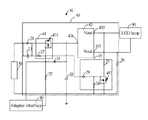
- FIG. 2 is a circuit diagram of the illumination apparatus of FIG. 1 .
- an illumination apparatus 10 includes a battery holder 20 , an adapter interface 30 , a driving circuit 40 , and an LED unit 50 .
- the battery holder 20 is configured to receive a battery (not shown).
- the apparatus 10 can receive power from an AC/DC adapter (not shown) via the adapter interface 30 .
- the adapter interface 30 is a USB interface. When the AC/DC adapter is connected to the apparatus 10 through the USB interface, the apparatus 10 automatically selects the AC/DC adapter as a power source to power the apparatus 10 .
- the driving circuit 40 includes a switch unit 41 , a driving unit 43 , and a branch connection unit 45 .
- the switch unit 41 When the AC/DC adapter is not connected to the apparatus 10 , the switch unit 41 is turned on to allow the driving unit 43 to receive power from the battery.
- the switch unit 41 When the AC/DC adapter is connected to the apparatus 10 , the switch unit 41 is turned off to allow the driving unit 43 to receive power from the AC/DC adapter.
- the branch connection unit 45 is connected to the LED unit 50 in parallel to ensure the driving current to the LED unit 50 is stable and uninterrupted.
- the switch unit 41 includes a transistor 411 and a first resistor 27 connected to the transistor 411 .
- the switch transistor 411 is a P-channel metal-oxide-semiconductor (PMOS) field-effect transistor.
- the source of the transistor 411 is connected to an anode of the battery holder 20
- the drain of the transistor 411 is connected to the driving unit 43
- the gate of the transistor 411 is connected to the adapter interface 30 and also grounded via a second resistor 22 .
- a first diode 21 is connected between the battery holder 20 and the source of the PMOS transistor 411
- a capacitor 23 is connected to the first diode 21 in parallel. The first diode 21 and the capacitor 23 enable the battery to output stable voltage.
- the driving unit 43 includes an input port 431 , a first voltage output port 433 , and a second voltage output port 435 .
- the battery holder 20 is connected to the input port 431 via the switch unit 41 , and the AC/DC adapter interface 30 is connected to the input port 431 via a second diode 31 .
- the anode of the second diode 31 is connected to the AC/DC adapter interface 30 via the second resistor 22
- the cathode of the second diode 31 is connected to the input port 431 and also grounded via a second capacitor 33 , which enables the AC/DC adapter to output stable voltage.
- the LED unit 50 is connected between the first voltage output port 433 and the second voltage output port 435 .
- the branch connection unit 45 includes a transistor 451 .
- the transistor 451 is an N-channel metal-oxide-semiconductor field-effect transistor.
- the gate of the transistor 451 is connected to the gate of the PMOS transistor 411 via a third resistor 29
- the drain of the transistor 451 is connected to the first voltage output port 433 via a fourth resistor 25
- the source of the NMOS transistor 451 is grounded.
- a fifth resistor 24 is connected between the gate and the source of the NMOS transistor 451 .
- the AC/DC adapter when connected to the illumination apparatus 10 , applies a voltage to the transistor 411 , which is accordingly turned off to prevent battery supply to the driving unit 43 . Simultaneously, the AC/DC adapter also applies a voltage to the transistor 451 , which is accordingly turned on. Accordingly, the AC/DC adapter can provide stable current to the LED unit 50 .
Abstract
Description
Claims (18)
Applications Claiming Priority (3)
| Application Number | Priority Date | Filing Date | Title |
|---|---|---|---|
| CN201010197727.5 | 2010-06-10 | ||
| CN201010197727.5A CN101861025B (en) | 2010-06-10 | 2010-06-10 | LED light emitting device and drive circuit thereof |
| CN201010197727 | 2010-06-10 |
Publications (2)
| Publication Number | Publication Date |
|---|---|
| US20110304277A1 US20110304277A1 (en) | 2011-12-15 |
| US8339065B2 true US8339065B2 (en) | 2012-12-25 |
Family
ID=42946584
Family Applications (1)
| Application Number | Title | Priority Date | Filing Date |
|---|---|---|---|
| US12/871,934 Expired - Fee Related US8339065B2 (en) | 2010-06-10 | 2010-08-31 | Driving circuit and illumination apparatus using the same |
Country Status (2)
| Country | Link |
|---|---|
| US (1) | US8339065B2 (en) |
| CN (1) | CN101861025B (en) |
Cited By (1)
| Publication number | Priority date | Publication date | Assignee | Title |
|---|---|---|---|---|
| DE102018203912A1 (en) | 2018-03-14 | 2019-09-19 | Rp-Technik Gmbh | Luminaire module, comprising a ballast for LEDs, in particular in a light of an emergency lighting system and operating method |
Families Citing this family (1)
| Publication number | Priority date | Publication date | Assignee | Title |
|---|---|---|---|---|
| TW201334625A (en) * | 2012-02-06 | 2013-08-16 | Luxul Technology Inc | AC LED driver circuit for high-voltage AC power source |
Citations (4)
| Publication number | Priority date | Publication date | Assignee | Title |
|---|---|---|---|---|
| US5332993A (en) * | 1990-11-07 | 1994-07-26 | Kabushiki Kaisha Toshiba | Power controlling apparatus with a power failure detecting function |
| CN1848593A (en) | 2005-04-15 | 2006-10-18 | 三星电子株式会社 | Electronic device having path of power supplied to display part switched according to whether external power is supplied |
| US20090154148A1 (en) * | 2006-01-30 | 2009-06-18 | Eveready Battery Company, Inc. | Battery powered lighting appliance |
| US20120068601A1 (en) * | 2006-04-21 | 2012-03-22 | Tridonicatco Gmbh & Co. Kg | Emergency lighting device for operating a light source, in particular an led |
Family Cites Families (2)
| Publication number | Priority date | Publication date | Assignee | Title |
|---|---|---|---|---|
| WO2006120884A1 (en) * | 2005-05-02 | 2006-11-16 | Shindengen Electric Manufacturing Co., Ltd. | Battery charging and lamp lighting control circuit |
| CN2831455Y (en) * | 2005-10-27 | 2006-10-25 | 精模电子科技(深圳)有限公司 | Portable battery pack with a.c/d.c charging interface |
-
2010
- 2010-06-10 CN CN201010197727.5A patent/CN101861025B/en not_active Expired - Fee Related
- 2010-08-31 US US12/871,934 patent/US8339065B2/en not_active Expired - Fee Related
Patent Citations (5)
| Publication number | Priority date | Publication date | Assignee | Title |
|---|---|---|---|---|
| US5332993A (en) * | 1990-11-07 | 1994-07-26 | Kabushiki Kaisha Toshiba | Power controlling apparatus with a power failure detecting function |
| CN1848593A (en) | 2005-04-15 | 2006-10-18 | 三星电子株式会社 | Electronic device having path of power supplied to display part switched according to whether external power is supplied |
| US20060232133A1 (en) * | 2005-04-15 | 2006-10-19 | Samsung Electronics Co., Ltd. | Electronic device having path of power supplied to display part switched according to whether external power is supplied |
| US20090154148A1 (en) * | 2006-01-30 | 2009-06-18 | Eveready Battery Company, Inc. | Battery powered lighting appliance |
| US20120068601A1 (en) * | 2006-04-21 | 2012-03-22 | Tridonicatco Gmbh & Co. Kg | Emergency lighting device for operating a light source, in particular an led |
Cited By (2)
| Publication number | Priority date | Publication date | Assignee | Title |
|---|---|---|---|---|
| DE102018203912A1 (en) | 2018-03-14 | 2019-09-19 | Rp-Technik Gmbh | Luminaire module, comprising a ballast for LEDs, in particular in a light of an emergency lighting system and operating method |
| DE102018203912B4 (en) | 2018-03-14 | 2023-02-02 | Rp-Technik Gmbh | Emergency light with a light module, comprising a ballast for lamps, in particular in an emergency light of an emergency lighting system, and operating method |
Also Published As
| Publication number | Publication date |
|---|---|
| US20110304277A1 (en) | 2011-12-15 |
| CN101861025A (en) | 2010-10-13 |
| CN101861025B (en) | 2014-07-09 |
Similar Documents
| Publication | Publication Date | Title |
|---|---|---|
| US7843084B2 (en) | Electronic device capable of automatically selecting a power source | |
| US8319651B2 (en) | Electronic device providing charge status | |
| US9679469B2 (en) | Remote control circuit | |
| US20110095615A1 (en) | Power source selection circuit and electronic device using the same | |
| US9350197B2 (en) | Charger and electronic device | |
| US8952650B2 (en) | Device and method for charging a master device using a detachable device | |
| ATE504190T1 (en) | AC LIGHT CURRENT LIGHT DIODE AND AC LED DRIVER METHOD AND APPARATUS | |
| US20150303821A1 (en) | Wall socket | |
| TW200705162A (en) | An electrical device with adjustable voltage | |
| GB0815772D0 (en) | Portable light power output system | |
| US20140184265A1 (en) | Test circuit for power supply unit | |
| US8339065B2 (en) | Driving circuit and illumination apparatus using the same | |
| US8553383B2 (en) | Under-voltage protection circuit for battery | |
| US20140347004A1 (en) | Charging control circuit and electronic device with the same | |
| US20120091812A1 (en) | Power switching device | |
| US9753879B2 (en) | Interface switching apparatus for switching between a plurality of power supply pins and input/output terminals | |
| WO2018133484A1 (en) | Control circuit compatible with battery power supply and external power supply | |
| US7928606B2 (en) | Input device | |
| US7982626B2 (en) | Proper grounding detection and alarm circuit for electronic device | |
| US20150130442A1 (en) | Dc reverse polarity detection | |
| US8960945B1 (en) | Personally portable solar-powered electrical energy source | |
| US9857400B2 (en) | Motherboard voltage testing device | |
| TWI513229B (en) | Powered device | |
| KR101228425B1 (en) | Power supply circuit for light sources, such as lighting led systems | |
| KR20160125732A (en) | Power supplying apparatus |
Legal Events
| Date | Code | Title | Description |
|---|---|---|---|
| AS | Assignment |
Owner name: HON HAI PRECISION INDUSTRY CO., LTD., TAIWAN Free format text: ASSIGNMENT OF ASSIGNORS INTEREST;ASSIGNORS:CHAO, YANG-JUI;CHENG, CHIEH-LUN;WEI, LIN-HAO;AND OTHERS;SIGNING DATES FROM 20100816 TO 20100820;REEL/FRAME:024912/0514 Owner name: HONG FU JIN PRECISION INDUSTRY (SHENZHEN) CO., LTD Free format text: ASSIGNMENT OF ASSIGNORS INTEREST;ASSIGNORS:CHAO, YANG-JUI;CHENG, CHIEH-LUN;WEI, LIN-HAO;AND OTHERS;SIGNING DATES FROM 20100816 TO 20100820;REEL/FRAME:024912/0514 |
|
| REMI | Maintenance fee reminder mailed | ||
| LAPS | Lapse for failure to pay maintenance fees | ||
| STCH | Information on status: patent discontinuation |
Free format text: PATENT EXPIRED DUE TO NONPAYMENT OF MAINTENANCE FEES UNDER 37 CFR 1.362 |
|
| FP | Lapsed due to failure to pay maintenance fee |
Effective date: 20161225 |