US8336816B2 - Sliding frame aircraft launcher - Google Patents
Sliding frame aircraft launcher Download PDFInfo
- Publication number
- US8336816B2 US8336816B2 US12/582,208 US58220809A US8336816B2 US 8336816 B2 US8336816 B2 US 8336816B2 US 58220809 A US58220809 A US 58220809A US 8336816 B2 US8336816 B2 US 8336816B2
- Authority
- US
- United States
- Prior art keywords
- sliding frame
- frame
- aircraft
- launcher
- sliding
- Prior art date
- Legal status (The legal status is an assumption and is not a legal conclusion. Google has not performed a legal analysis and makes no representation as to the accuracy of the status listed.)
- Active, expires
Links
- 238000000034 method Methods 0.000 description 10
- 238000000926 separation method Methods 0.000 description 9
- IJGRMHOSHXDMSA-UHFFFAOYSA-N Atomic nitrogen Chemical compound N#N IJGRMHOSHXDMSA-UHFFFAOYSA-N 0.000 description 4
- 230000003213 activating effect Effects 0.000 description 4
- 239000012530 fluid Substances 0.000 description 4
- 230000035939 shock Effects 0.000 description 3
- 239000004677 Nylon Substances 0.000 description 2
- 230000007613 environmental effect Effects 0.000 description 2
- 238000007373 indentation Methods 0.000 description 2
- 238000012423 maintenance Methods 0.000 description 2
- 230000007246 mechanism Effects 0.000 description 2
- 229910052757 nitrogen Inorganic materials 0.000 description 2
- 229920001778 nylon Polymers 0.000 description 2
- 230000001133 acceleration Effects 0.000 description 1
- 230000002411 adverse Effects 0.000 description 1
- 230000015556 catabolic process Effects 0.000 description 1
- 239000011248 coating agent Substances 0.000 description 1
- 238000000576 coating method Methods 0.000 description 1
- 239000002131 composite material Substances 0.000 description 1
- 238000010276 construction Methods 0.000 description 1
- 238000006731 degradation reaction Methods 0.000 description 1
- 239000000428 dust Substances 0.000 description 1
- 230000000694 effects Effects 0.000 description 1
- 239000007789 gas Substances 0.000 description 1
- 230000000977 initiatory effect Effects 0.000 description 1
- 239000004576 sand Substances 0.000 description 1
Images


Classifications
-
- B—PERFORMING OPERATIONS; TRANSPORTING
- B64—AIRCRAFT; AVIATION; COSMONAUTICS
- B64F—GROUND OR AIRCRAFT-CARRIER-DECK INSTALLATIONS SPECIALLY ADAPTED FOR USE IN CONNECTION WITH AIRCRAFT; DESIGNING, MANUFACTURING, ASSEMBLING, CLEANING, MAINTAINING OR REPAIRING AIRCRAFT, NOT OTHERWISE PROVIDED FOR; HANDLING, TRANSPORTING, TESTING OR INSPECTING AIRCRAFT COMPONENTS, NOT OTHERWISE PROVIDED FOR
- B64F1/00—Ground or aircraft-carrier-deck installations
- B64F1/04—Launching or towing gear
- B64F1/06—Launching or towing gear using catapults
-
- B—PERFORMING OPERATIONS; TRANSPORTING
- B64—AIRCRAFT; AVIATION; COSMONAUTICS
- B64U—UNMANNED AERIAL VEHICLES [UAV]; EQUIPMENT THEREFOR
- B64U70/00—Launching, take-off or landing arrangements
- B64U70/70—Launching or landing using catapults, tracks or rails
-
- B—PERFORMING OPERATIONS; TRANSPORTING
- B64—AIRCRAFT; AVIATION; COSMONAUTICS
- B64U—UNMANNED AERIAL VEHICLES [UAV]; EQUIPMENT THEREFOR
- B64U10/00—Type of UAV
- B64U10/25—Fixed-wing aircraft
Definitions
- the present invention relates generally to aircraft launchers, and more specifically, to unmanned air vehicle (UAV) launchers.
- UAV unmanned air vehicle
- UAV launchers Three major types of UAV launchers known in the art are mechanical spring launchers, pneumatic launchers, and hydro-pneumatic launchers. Typically, hydro-pneumatic launchers are the most powerful and compact of known UAV launchers, and as a result, hydro-pneumatic launchers account for the majority of launchers on the market today.
- UAV launchers use an inclined rail in conjunction with a system to accelerate the UAV up the rail for launch, such as a shuttle.
- the length of the rail is too large to facilitate tactical transport and mobility of the launcher when in its operative state.
- most known UAV launchers are transported in a partially disassembled state, and assembled at the launch site. Accordingly, minimizing the time and complexity of the assembly and disassembly process is typically the subject of most UAV design efforts.
- UAV launchers are typically large in size.
- the size of the launchers can create problems in military environments, such as, for example:
- the size of the UAV launcher may exceed the amount of deck space that is available.
- UAV launchers using relatively short rails can have setbacks as well.
- UAV launchers with short rails typically impart large launching loads over the short span of the rails.
- the UAV may need to be reinforced to survive these loads, which can increase the weight of the UAV.
- the increased weight of the UAV may have undesirable effects on it, for example, it may reduce the endurance of the UAV.
- an aircraft launcher can comprise a base frame; a first sliding frame that slides with respect to the base frame; a second sliding frame that slides with respect to the first sliding frame; an aircraft support located on the second sliding frame; and a drive apparatus adapted to slide at least one of the first sliding frame and the second sliding frame with respect to the base frame.
- the first sliding frame can slide along a first axis
- the second sliding frame can slide along a second axis substantially parallel to the first axis.
- the aircraft launcher can further include a timing apparatus that coordinates sliding of the first sliding frame and the second sliding frame with respect to the base frame.
- the drive apparatus can impart movement to the first sliding frame with respect to the base frame
- the timing apparatus can impart movement to the second sliding frame with respect to the base frame.
- the timing apparatus can comprise a belt coupled to the base frame, the first sliding frame, and the second sliding frame.
- the drive apparatus can comprise an actuator that imparts movement to at least one of the first sliding frame and the second sliding frame with respect to the base frame.
- the actuator can comprise a linear actuator.
- the actuator can be coupled to at least one of the first sliding frame and the second sliding frame via a pulley system.
- the aircraft launcher can further comprise a hydraulic circuit that powers the actuator.
- the aircraft launcher can further comprise an arresting apparatus that decelerates or stops movement of the first sliding frame and the second sliding frame with respect to the base frame.
- the arresting apparatus can comprise a belt coupled to at least one of the first sliding frame and the second sliding frame.
- the arresting apparatus can further comprise an elastic member coupled to the belt.
- the aircraft support can comprise a cradle including a first pivot arm adapted to pivot into engagement with a first side of an aircraft, and a second pivot arm adapted to pivot into engagement with a second, opposite side of the aircraft.
- the aircraft launcher can further comprise a first shear member adapted to hold the first pivot arm in engagement with the first side of the aircraft; and a second shear member adapted to hold the second pivot arm in engagement with the second side of the aircraft; wherein at least one of the first shear member or the second shear member shears when the aircraft separates from the cradle during launch.
- the aircraft launcher can further comprise a first anti-friction slide located between the base frame and the first sliding frame; and a second anti-friction slide located between the first sliding frame and the second sliding frame.
- the aircraft launcher can further comprise at least one roller bearing located between the base frame and the second sliding frame.
- the present invention also relates to a method of launching an aircraft.
- the method can comprise retracting a first sliding frame with respect to a base frame in a first direction; retracting a second sliding frame with respect to the first sliding frame in the first direction, the second sliding frame supporting an aircraft; extending the first sliding frame with respect to the base frame in a second direction opposite to the first direction; and extending the second sliding frame with respect to the first sliding frame in the second direction, thereby launching the aircraft from the second sliding frame.
- extending the first sliding frame with respect to the base frame in the second direction can comprise activating an actuator that imparts movement to the first sliding frame with respect to the base frame.
- Extending the second sliding frame with respect to the first sliding frame in the second direction can comprise moving a timing apparatus coupled to the base frame and at least one of the first sliding frame and the second sliding frame.
- the method can further comprise arresting movement of the first sliding frame and the second sliding frame in the second direction in order to launch the aircraft from the second sliding frame.
- an illustrative embodiment can comprise retracting the first sliding frame and the second sliding frame in the first direction into a storage position. When in the storage position, the base frame, the first sliding frame, and the second sliding frame can substantially completely overlap one another.
- extending the first sliding frame with respect to the base frame in the second direction, and extending the second sliding frame with respect to the first sliding frame in the second direction comprise activating a switch on a hand-held control unit.
- the aircraft launcher can comprise a base frame; a sliding frame that slides with respect to the base frame, the sliding frame defining a longitudinal length; an aircraft support located on the sliding frame; and a drive apparatus adapted to slide the sliding frame with respect to the base frame between a fully retracted position and a fully extended position; wherein about one-half or less of the longitudinal length of the sliding frame overlaps the base frame when in the fully retracted position, and about one-half or less of the longitudinal length of the sliding frame overlaps the base frame when in the fully extended position.
- FIG. 1 is a side, partially exploded view of an illustrative UAV launcher according to the present invention
- FIG. 2 is a side, partially exploded view of an illustrative UAV launch sequence according to the present invention
- FIG. 3 is a side, partially exploded view of an illustrative timing system for the UAV launcher of FIG. 1 ;
- FIG. 4 is a side, partially exploded view of an illustrative drive system for the UAV launcher of FIG. 1 ;
- FIG. 5 is a schematic representation of an illustrative hydraulic circuit for the illustrative drive system of FIG. 4 ;
- FIG. 6 is a side, partially exploded view of an illustrative arresting system for the UAV launcher of FIG. 1 ;
- FIG. 7 is a side, partially exploded view of an illustrative timing system according to an alternative embodiment of the present invention.
- FIG. 8 is a side view showing the stroke of an illustrative UAV launcher according to the present invention.
- FIG. 9 is a side, partially exploded view of an illustrative drive system according to an alternative embodiment of the present invention.
- FIG. 10 is a cross-sectional view of the base frame, first sliding frame, and second sliding frame of an illustrative UAV launcher according to the present invention, taken along lines 10 - 10 of FIG. 1 ;
- FIG. 11 is a side, partially exploded view illustrating the operation of the illustrative arresting system of FIG. 6 ;
- FIG. 12 is a side view of an illustrative trailer containing an illustrative UAV launcher according to the present invention.
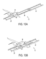
- FIGS. 13A-F are perspective views depicting an illustrative UAV launch sequence according to the present invention.
- FIG. 14 is a schematic representation of an illustrative hydraulic circuit according to an alternative embodiment of the present invention.
- FIG. 15 is a side, partially exploded view of an illustrative arresting system according to an alternative embodiment of the present invention.
- FIG. 16 is a perspective, partially exploded view of an illustrative UAV launcher according to an alternative embodiment of the present invention.
- FIG. 17 is a side view of an illustrative aircraft cradle according to the present invention.
- FIG. 18 is a top view of the illustrative aircraft cradle of FIG. 17 ;
- FIG. 19 is a schematic representation of an illustrative hydraulic circuit according to an alternative embodiment of the present invention.
- the present invention relates to an aircraft launcher and related method.
- the aircraft launcher and related method will be described in the context of an unmanned air vehicle (UAV) launcher.
- UAV unmanned air vehicle
- An example of an UAV that can be launched with the present invention is an Aerosonde 470 made by Aerosonde, which is located at Unit 1, 585 Blackburn Road, Notting Hill, Victoria, Australia, 3168.
- Aerosonde 470 made by Aerosonde, which is located at Unit 1, 585 Blackburn Road, Notting Hill, Victoria, Australia, 3168.
- the UAV launcher of the present invention can be used with other types and sizes of UAVs.
- the UAV launcher can be quick and easy to use, and can require little or no assembly at the launch site.
- the UAV launcher can be compact, allowing it to be easily stored in a transport position when not in use.
- an illustrative embodiment can be as small as seven feet long by eighteen inches wide, by sixteen inches deep.
- the launcher may be seven feet long by twenty-nine inches wide, by thirty-two inches deep. The compact size can facilitate protection of the UAV launcher between launches, for example, by allowing a transport cover to be installed over the UAV launcher.
- an illustrative UAV launcher according to the present invention can provide for a “soft launch” of the UAV, where acceleration forces on the UAV are reduced. Further, an illustrative UAV launcher according to the present invention can have a high power-to-weight ratio, and/or can be of low cost construction.
- the UAV launcher 10 can comprise a sliding frame 12 , shown in FIG. 1 , which can have a generally ladder-like framework configuration, however, other configurations are possible. According to an illustrative embodiment, the sliding frame 12 can move between a “start-launch” position (shown in the left-hand side of FIG. 2 ) and an “aircraft separation” position (shown in the right-hand side of FIG. 2 ).
- the UAV launcher 10 can further include a frame timing system 14 , shown in FIG. 3 , and a drive system 16 , shown in FIG. 4 .
- the UAV launcher 10 can additionally include a hydraulic circuit 18 for the drive system 16 , shown in FIG. 5 , as well as an arresting system 20 , shown in FIG. 6 .
- the UAV launcher 10 can include a base frame 22 that can rest on the ground or on a transport surface, such as the bed of a truck.
- the UAV launcher 10 can also include a first sliding frame 24 and a second sliding frame 26 , which can slide with respect to the base frame 22 .
- the base frame 22 , first sliding frame 24 , and second sliding frame 26 are shown separated from one another in FIG. 1 , however, in application, these members can be coupled to one another, for example, by a first anti-friction slide 28 and a second anti-friction slide 30 , however, other configurations are possible.
- the UAV launcher 10 is illustrated in FIG.
- timing system 14 may be omitted. In illustrative embodiments having three or more sliding frames, multiple timing systems 14 may be used.
- an illustrative embodiment can include a pivot 32 , such as an aft incline pivot, that can be used to adjust the vertical trajectory of the UAV launcher 10 .
- An incline link 34 or other structure, can be used in conjunction with the pivot 32 to lock-in the vertical trajectory.
- the pivot 32 and incline link 34 can be used to position the UAV launcher 10 at an inclination of between about 10 and about 25 degrees with respect to the ground, and preferably between about 11 and about 13 degrees, however, other trajectories are possible.
- an alternative embodiment of the UAV launcher 10 can pivot near it's front end in order to allow the launcher 10 to pivot forward to reduce loads during deceleration of the sliding frame 12 (e.g., during operation of the arresting system).
- the first sliding frame 24 can slide with respect to the base frame 22 along a first axis A 1 .
- the second sliding frame 26 can slide with respect to the first sliding 24 frame along a second axis A 2 .
- An aircraft support 36 such as an aircraft cradle, can be located on the second sliding frame 26 to support an aircraft 38 , such as an UAV, on the UAV launcher 10 .
- the drive system 16 and/or hydraulic circuit 18 can be housed within the base frame 22 , or mounted on or near the base frame 22 .
- first axis A 1 and the second axis A 2 can be substantially parallel to one another, such that the first sliding frame 24 and second sliding frame 26 move with respect to one another in a telescoping manner.
- the base frame 22 , first sliding frame 24 , and second sliding frame 26 are shown as being stacked on top of one another in the vertical direction, these components can alternatively partially overlap with one another in the vertical direction (as shown, for example, in FIG. 10 ), or alternatively, can be arranged concentrically with respect to one another (e.g., completely nest within one another).
- FIG. 2 depicts an illustrative launch sequence according to the present invention.
- the UAV launcher 10 is shown in an illustrative “start launch” position on the left-hand side of FIG. 2 .
- start launch position on the left-hand side of FIG. 2 .
- the first sliding frame 24 and the second sliding frame 26 have been fully retracted with respect to the base frame 22 along the first axis and second axis, respectively.
- An aircraft such as an UAV 38 , can be supported on the aircraft cradle 36 , and is ready to launch.
- FIG. 2 shows the UAV launcher in an illustrative “aircraft separation” position, where the first sliding frame 24 and the second sliding frame 26 have substantially fully extended, e.g., reached full stroke in the forward direction, and the UAV 38 begins separation from the aircraft cradle 36 .
- the right-hand side FIG. 2 shows the UAV launcher 10 in an illustrative “finish launch” position, where the UAV 38 has completely separated from the UAV launcher 10 , and is in flight.
- FIG. 3 depicts an illustrative timing system 14 for the first sliding frame 24 and the second sliding frame 26 .
- FIG. 3 is a partially-exploded view in order to better illustrate the timing system 14 .
- the timing system 14 can coordinate sliding of the first sliding frame 24 and the second sliding frame 26 with respect to the base frame 22 .
- the timing system 14 can comprise a first belt 40 A and a second belt 40 B, each coupled to the base frame 22 , the first sliding frame 24 , and the second sliding frame 26 .
- the term “belt” is used generically throughout this application to include belts, timing belts, cables, ropes, chains, or other similar structures known in the art.
- the belts 40 A, 40 B are anchored to the base frame 22 and the second sliding frame 26 , and coupled to the first sliding frame 24 by, for example, rollers 42 , however, other configurations are possible.
- the belts 40 A, 40 B can coordinate movement between the first sliding frame 24 and the second sliding frame 26 , such that retraction (i.e., movement to the left in FIG. 3 ) of the first sliding frame 24 imparts similar movement in the same direction to the second sliding frame 26 , or vice versa.
- extension (i.e., movement to the right in FIG. 3 ) of the first sliding frame 24 can impart similar movement in the same direction to the second sliding frame 26 , or vice versa.
- FIG. 7 is an alternative embodiment of the timing system of FIG. 3 , comprising a single belt 40 anchored to the base frame 22 and second sliding frame 26 in a single location.
- the belt 40 of FIG. 7 can alternatively comprise two or more belts joined together where anchored to the base frame 22 and second sliding frame 26 .
- the timing system 14 may include two or more sets of belts located in parallel to one another (e.g., on opposite lateral sides of the UAV launcher 10 ) to balance the loads on the launcher.
- FIG. 4 depicts an illustrative drive system 16 for the UAV launcher 10 of the present invention.
- the drive system 16 can include a linear actuator 44 , such as a cylinder, however other configurations are possible.
- the linear actuator 44 can be attached to a pulley system 48 (which includes a plurality of pulleys 48 A), which in the illustrative embodiment shown, magnifies the stroke of the linear actuator 44 by five times, however, other configurations are possible.
- the drive system 16 can be anchored with respect to the UAV launcher 10 (e.g., mounted in, on, or near the base frame), and the pulley 50 can have it's distal end 52 attached to one of the sliding frame members 24 , 26 , such as the first sliding frame member 24 , as shown.
- FIG. 4 depicts the UAV launcher 10 in a storage position, in which the base frame 22 , first sliding frame 24 , and second sliding frame 26 substantially completely overlap one-another in the length-wise direction, resulting in at least the sliding frame 12 component of the UAV launcher 10 having a compact overall length L.
- the UAV launcher 10 may be located in the storage position prior to being setup for launch, or after completing a launch. From the storage position, retraction of the first and second sliding members 24 , 26 to a start launch position can cause the belt 50 to unwind from the pulley system 48 , and hence can extend the linear actuator 44 .
- Retracting the linear actuator 44 can cause the belt 50 to retract into the pulley system 48 , and hence, can cause the first sliding frame 24 to extend (i.e., move to the right in FIG. 4 ).
- the timing system 14 described above, and shown in FIGS. 3 and 7 , can cause the second sliding frame 26 to extend as well, thus causing the UAV launcher 10 to launch the aircraft.
- FIG. 5 will be discussed below with reference to FIG. 19 .
- FIG. 6 depicts an illustrative arresting system 20 for the UAV launcher 10 of the present invention.
- the arresting system 20 can stop movement of the sliding frame 12 (e.g., first and second sliding frames 24 , 26 ) at or around the time of launch. This can prevent shock to the UAV 38 and/or the UAV launcher 10 when the sliding frame 12 reaches full mechanical extension.
- the arresting system 20 can comprise a belt 54 , such as a nylon strap, composite cable, or synthetic rope connected to an elastic tensioning device 56 , such as a ratchet, spring or gas damper.
- the belt 54 can pass through rollers 58 located on the base frame 22 , the first sliding frame 24 , and/or the second sliding frame 26 , and can be anchored to the second sliding frame 26 .
- the length of the belt 54 and the stroke of the tensioner 56 can be adapted to decelerate (or stop) the first and/or second sliding frames 24 , 26 at or around the time of the UAV launch, in order to dampen shock to the UAV and/or the UAV launcher 10 .
- the drive system 16 can be used as an arresting system.
- FIG. 15 depicts an alternative embodiment of the arresting system 20 of the present invention, in which the belt 54 is routed in a different manner via the pulleys 58 .
- the arresting system 20 can alternatively comprise two or more belts 54 and tensioning devices 56 arranged in parallel. According to an illustrative embodiment, the arresting system 20 can stop movement of the second sliding frame 26 , and the timing system 14 can in turn stop movement of the first sliding frame 24 , however, other configurations are possible.
- FIG. 11 depicts an illustrative operation of the arresting system 20 of FIG. 6 .
- the top of FIG. 11 shows the position of the belt 54 when the UAV launcher 10 is in the fully retracted, or “start launch” position.
- the middle of FIG. 11 shows the position of the belt 54 when the UAV launcher 10 is between the fully retracted position and a fully extended position, or “aircraft separation” position.
- the bottom of FIG. 11 shows the position of the belt 54 at or around the “aircraft separation” position.
- the belt 54 applies a tension force to the tensioner 56 , which acts to dampen the forces of the belt 54 , and accordingly, softly decelerate the UAV launcher.
- the arresting system 20 can prevent excessive shock forces to the UAV and/or the UAV launcher.
- FIG. 8 depicts the stroke for an illustrative embodiment of a UAV launcher 10 having two sliding frames according to the present application.
- the illustrative embodiment of FIG. 8 shows the first sliding frame 24 overlapping the base frame 22 by approximately 1 ⁇ 3 of its length when in the retracted and extended positions, and the second sliding frame 26 overlapping the first sliding frame 24 by the same amount when in the retracted and extended positions.
- the UAV launcher 10 can have a total stroke (e.g., from the “start-launch position” to the “aircraft separation” position) of approximately 2.67 times the length of the sliding frame 12 when in the stored position.
- This ratio can be altered, for example, by adjusting the amount of overlap between frame members when in the extended and retracted positions, or by adding additional sliding frame members.
- an illustrative embodiment may have a single sliding frame 24 that overlaps the base frame 22 by one-half or less of it's longitudinal length when in both the retracted and extended positions.
- FIG. 8 shows the sliding frame 24 having a longitudinal length L that is overlapping the base frame 22 by approximately one-third of length L.
- FIG. 9 will be discussed below with reference to FIG. 19 .
- FIG. 10 depicts an exemplary cross-sectional view of an illustrative base frame 22 , first sliding frame 24 , and second sliding frame 26 of the present invention.
- the cross-section is taken along line 10 - 10 of FIG. 1 .
- the base frame 22 , first sliding frame 24 , and the second sliding frame 26 can overlap one another, for example, their adjacent side rails can nest within one another.
- the upper flange 22 ′ of the base frame can be in overlapping engagement with the lower flange 24 ′ of the first sliding frame 24
- the lower flange 26 ′ of the second sliding frame 26 can be in overlapping engagement with the upper flange 24 ′′ of the first sliding frame 24
- a roller 60 as shown in FIG. 10 , or other apparatus can be located between the lower flange 26 ′ of the second sliding frame 26 and the upper flange 22 ′ of the base frame 22 to reduce friction, however, other friction reducing mechanisms are also possible, such as a linear bearing, nylon slide, or low-friction coating.
- FIG. 12 depicts an illustrative embodiment of a UAV launcher 10 according to the present invention in a storage position, located in a trailer 64 to facilitate transportation of the UAV launcher 10 .
- Tie downs or other types of anchors may be used to hold the UAV launcher in a desired position, for example, during transportation, or during launch.
- the trailer 64 can include a hinged rear ramp 66 .
- the trailer 64 can further include a forward screw jack 68 , located, for example, on the trailer tongue, and/or one or more rearward screw jacks 70 which can be located towards the rear of the trailer 64 .
- the screw jacks 68 , 70 can rest on the ground to provide stability to the trailer 64 , for example, during launch.
- Wheel chocks 72 can be used to further stabilize the trailer 64 .
- a method of launching an UAV 38 can comprise retracting the first sliding frame 24 and the second sliding frame 26 in a first, or rearward direction with respect to the base frame 22 , for example, to the position shown in FIG. 13A . This can be done manually, for example, or alternatively, through a power source associated with the launcher 10 .
- the method can further comprise extending the first sliding frame 24 and the second sliding frame 26 in a second, or forward direction with respect to the base frame 22 , for example, until the sliding frame 12 reaches maximum extension, as shown in FIG. 13D .
- the UAV 38 may separate from the launcher, for example, as shown in FIG. 13E , at which point, the UAV 38 may be in flight.
- movement of the second sliding frame 26 in the forward direction can be accomplished, for example, via the timing system 14 , shown, for example, in FIGS. 3 and 7 , which translates movement of the first sliding frame 24 into movement of the second sliding frame 26 , however, other methods are possible.
- the sliding frame 12 can be decelerated and/or stopped, for example, using an arresting system, such as the illustrative arresting systems 20 shown in FIGS. 6 , 11 , and 15 .
- the sliding frame 12 can be returned to a storage position, shown, for example, in FIG. 13F , where the base frame 22 , first sliding frame 24 , and second sliding frame 26 substantially completely overlap one another in the lengthwise direction, thereby allowing the launcher 10 to have a compact configuration.
- FIG. 14 will be discussed below with reference to FIG. 19 .
- FIG. 16 a partially exploded, perspective view of an illustrative embodiment of the sliding frame 12 is shown.
- the first sliding frame 24 and the second sliding frame 26 can comprise opposed side rails interconnected with a lattice-type structure, however, other configurations are possible.
- the base frame 22 can support the drive system 16 , which in the illustrative embodiment shown, is mounted in or on the base frame.
- the aircraft support 36 can comprise a cradle mounted to the second sliding frame 26 .
- the cradle can comprise opposed left and right uprights 76 , 78 that can cradle the opposite sides of the aircraft's fuselage, or other portion of the aircraft 38 .
- Each upright 76 , 78 can include a respective pivot arm 76 P, 78 P that pivots with respect to the respective upright 76 , 78 (see the arrows A in FIG. 18 ).
- a pivot bearing 77 and damper assembly 79 can be used to adjust the trajectory of the sliding frame 12 .
- each pivot arm 76 P, 78 P can pivot about the respective uprights 76 , 78 toward (see arrows A in FIG. 18 ) and away from the UAV 38 .
- This may facilitate mounting of the UAV 38 to the aircraft support 36 .
- each pivot arm 76 P, 78 P can include a distal portion that engages with a portion of the UAV 38 , such as indentations 80 on, for example, both sides of the UAV 38 , or other structures.
- the pivot arms 76 P, 78 P can be pivoted into engagement with the indentations 80 to support the UAV 38 .
- a shear member such as a shear pin (not shown), can engage both the upright 76 , 78 , and the respective pivot arm 76 P, 78 P.
- the shear members can lock each pivot arm 76 P, 78 P in the position where they engage the UAV 38 , for example, prior to launch.
- the shear members can be configured to hold the pivot arms 76 P, 78 P from rotating under forward forces of the UAV when it's propeller is turning at full thrust. For example, the UAV's engine can be run at full RPM and the pivot arms 76 P, 78 P will still hold the UAV in position.
- the pivot arms 76 P, 78 P won't release the UAV until the arresting system 20 stops forward movement of the sliding frame 12 .
- the forward forces of the UAV 38 may be transmitted to the pivot arms 76 P, 78 P, which in turn, may tend to rotate the pivot arms 76 P, 78 P with respect to the uprights 76 , 78 in the opposite direction of arrows A in FIG. 18 .
- the shear members can have a low enough shear strength such that the forward forces of the UAV 38 shear the shear members, and allow the pivot arms 76 P, 78 P to pivot counter to arrows A in FIG.
- the shear members can be replaced with new ones when the UAV launcher 10 is to be re-used. In the case where the UAV 38 is not launched, the shear members can be removed by the operator to facilitate removal of the UAV 38 from the aircraft support structure.
- the shear members can be removed by the operator to facilitate removal of the UAV 38 from the aircraft support structure.
- FIGS. 5 , 9 , 14 , and 19 depict various illustrative hydraulic circuits 18 that may be used to operate the drive system 16 (e.g., to power the actuator 44 of FIG. 4 ).
- an illustrative embodiment of the circuit 18 can include a hydraulic pump 80 powered, for example, by a DC motor 82 .
- a relief valve 84 and an accumulator 86 can be connected to the output of the pump 80 , for example, in line with one another.
- the accumulator 86 can comprise a nitrogen-over-oil accumulator used to store energy for powering the actuator 44 .
- a poppet valve 88 can also be connected to the output of pump 80 .
- a valve 90 can be connected to the output of the pump 80 and the input of poppet valve 88 .
- a momentary vent valve 92 can be connected to the output of the poppet valve 88 .
- the actuator 44 can also be connected to the output of the poppet valve 88 .
- FIG. 9 depicts an illustrative embodiment where the hydraulic circuit 18 can include a relatively small valve 94 for applying a pre-tension to the actuator 44 , and a relatively large valve 92 for operating the actuator 44 to launch the UAV.
- FIG. 14 depicts an alternative illustrative hydraulic circuit 18 that can be used with the present invention.
- this alternative can use an electronically adjustable control valve 97 for supplying fluid to the hydraulic actuator 44 . Adjustments in the electrical control signal can result in actuator speed changes.
- This circuit 18 may increase the aircraft weight and/or operating temperature range.
- FIG. 19 depicts another alternative hydraulic circuit 18 that can be used with the present invention.
- the hydraulic circuit 18 can include an AC electric motor 82 that drives a hydraulic pump 80 .
- the pump 80 can be connected to a manual shutoff valve 98 that typically remains open, but can be closed, for example, during maintenance of the launcher 10 .
- the hydraulic circuit 18 can further include a pair of accumulators 86 connected with the hydraulic actuator 44 .
- the accumulators 86 can store energy as compressed nitrogen and hydraulic fluid.
- launch cycle initiation can cause the hydraulic pump 80 to impel hydraulic fluid into the accumulators 86 , compressing the nitrogen reservoir.
- the circuit 18 can further include pilot valves 100 that release the hydraulic fluid from the accumulators 86 into the hydraulic actuator 44 , for example, in response to a launch signal.
- the circuit 18 can include an electrically actuated pilot valve 110 , which can operate pilot valves 100 when current is applied (e.g., in response to a launch signal). Additionally, the circuit 18 can include an electrically operated vent valve 112 , that can vent the circuit 18 .
- an electrically actuated pilot valve 110 which can operate pilot valves 100 when current is applied (e.g., in response to a launch signal).
- the circuit 18 can include an electrically operated vent valve 112 , that can vent the circuit 18 .
- other types of drive systems such as pneumatic, mechanical, and electrical can be used.
Priority Applications (1)
| Application Number | Priority Date | Filing Date | Title |
|---|---|---|---|
| US12/582,208 US8336816B2 (en) | 2008-10-20 | 2009-10-20 | Sliding frame aircraft launcher |
Applications Claiming Priority (2)
| Application Number | Priority Date | Filing Date | Title |
|---|---|---|---|
| US10686808P | 2008-10-20 | 2008-10-20 | |
| US12/582,208 US8336816B2 (en) | 2008-10-20 | 2009-10-20 | Sliding frame aircraft launcher |
Publications (2)
| Publication Number | Publication Date |
|---|---|
| US20100096496A1 US20100096496A1 (en) | 2010-04-22 |
| US8336816B2 true US8336816B2 (en) | 2012-12-25 |
Family
ID=42107874
Family Applications (1)
| Application Number | Title | Priority Date | Filing Date |
|---|---|---|---|
| US12/582,208 Active 2031-01-31 US8336816B2 (en) | 2008-10-20 | 2009-10-20 | Sliding frame aircraft launcher |
Country Status (6)
| Country | Link |
|---|---|
| US (1) | US8336816B2 (fr) |
| EP (1) | EP2342129B1 (fr) |
| DK (1) | DK2342129T3 (fr) |
| ES (1) | ES2597502T3 (fr) |
| PL (1) | PL2342129T3 (fr) |
| WO (1) | WO2010048176A1 (fr) |
Cited By (9)
| Publication number | Priority date | Publication date | Assignee | Title |
|---|---|---|---|---|
| US20150060600A1 (en) * | 2013-08-27 | 2015-03-05 | Engineered Arresting Systems Corporation | Electric unmanned aerial vehicle launcher |
| US9284043B2 (en) | 2013-11-21 | 2016-03-15 | Aai Corporation | Evaluating aileron deflection while an unmanned aerial vehicle is in flight |
| US9453705B2 (en) | 2014-02-21 | 2016-09-27 | Lockheed Martin Corporation | Payload launcher and autonomous underwater vehicle |
| US20170313442A1 (en) * | 2016-05-02 | 2017-11-02 | Circor Aerospace, Inc. | Aerial vehicle launcher |
| US9862505B2 (en) | 2014-03-26 | 2018-01-09 | Aai Corporation | Techniques for emplacing an unmanned aerial vehicle launcher prior to launching an unmanned aerial vehicle |
| US9957064B2 (en) | 2015-05-08 | 2018-05-01 | Aai Corporation | Utilizing an unmanned aerial vehicle platform which is equipped with a turntable assembly |
| US10118713B2 (en) | 2013-08-27 | 2018-11-06 | Engineered Arresting Systems Corporation | Electric unmanned aerial vehicle launcher |
| US10259594B2 (en) * | 2015-12-23 | 2019-04-16 | Postech Academy-Industry Foundation | Apparatus and method for recovering and launching unmanned aerial vehicle |
| US10464693B2 (en) | 2015-09-04 | 2019-11-05 | Lockheed Martin Corporation | Launch canister with air bag ram |
Families Citing this family (6)
| Publication number | Priority date | Publication date | Assignee | Title |
|---|---|---|---|---|
| US8894006B2 (en) | 2012-04-19 | 2014-11-25 | Wintec Arrowmaker, Inc. | Man-portable, multi-mode unmanned aerial system launcher |
| CN105667822B (zh) * | 2016-03-30 | 2018-07-27 | 成都天空营地科技有限公司 | 一种飞行器循环传送牵引系统 |
| JP7110086B2 (ja) * | 2018-12-20 | 2022-08-01 | 株式会社クボタ | 牽引装置及びこれを備える作業車両 |
| CN110576980B (zh) * | 2019-09-02 | 2021-01-05 | 宋清泉 | 一种用于测绘的无人机弹起装置 |
| CN111216916A (zh) * | 2019-12-04 | 2020-06-02 | 吉林省国遥博诚科技股份有限公司 | 无人机弹射架 |
| CN117429651B (zh) * | 2023-11-17 | 2024-03-19 | 广州天海翔航空科技有限公司 | 适用于海洋环境的无人机弹射装置 |
Citations (48)
| Publication number | Priority date | Publication date | Assignee | Title |
|---|---|---|---|---|
| US922711A (en) * | 1908-08-25 | 1909-05-25 | James Means | Apparatus for launching flying-machines. |
| US922710A (en) * | 1908-08-20 | 1909-05-25 | James Means | Apparatus for launching flying-machines. |
| US975953A (en) * | 1910-03-05 | 1910-11-15 | Iskander Hourwich | Aerial projecting apparatus. |
| US1347105A (en) * | 1920-05-05 | 1920-07-20 | Whitworth & Co | Airplane-launching apparatus |
| US1535475A (en) * | 1924-02-08 | 1925-04-28 | Carl F Jeansen | Airplane catapult |
| US1777167A (en) * | 1928-11-09 | 1930-09-30 | Forbes William Archib Davidson | Apparatus for launching aircraft |
| US1797514A (en) * | 1927-04-29 | 1931-03-24 | Deutsche Werke Kiel Ag | Starting device for aeroplanes |
| US1798880A (en) * | 1929-04-18 | 1931-03-31 | Heinkel Ernst | Airplane-launching track |
| US1802649A (en) * | 1927-03-10 | 1931-04-28 | Heinkel Ernst | Airplane-launching apparatus |
| US1879765A (en) * | 1930-08-15 | 1932-09-27 | Ransomes & Rapier Ltd | Apparatus for launching aircraft |
| US1887528A (en) * | 1928-07-23 | 1932-11-15 | Ernst Heinkel | Airplane launching track |
| US1898884A (en) * | 1931-03-31 | 1933-02-21 | Mitchell Colin Campbell | Retarding gear for catapults |
| US1960264A (en) * | 1931-10-11 | 1934-05-29 | Heinkel Ernst | Catapult for launching aeroplanes |
| US2083805A (en) * | 1932-11-22 | 1937-06-15 | Adams Herbert Luther | Launching device |
| US2375449A (en) * | 1942-04-01 | 1945-05-08 | Unger Maurice | Method and means for facilitating the landing and take-off of airplanes from movable runways |
| US2672306A (en) * | 1951-01-05 | 1954-03-16 | All American Eng Co | Flywheel type catapult launching means |
| US2756950A (en) * | 1954-10-07 | 1956-07-31 | Cleveland Pneumatic Tool Co | Aircraft launching device, including a rocket propelled ball screw and nut |
| US2926871A (en) * | 1957-01-14 | 1960-03-01 | Bless Harold | Gas operated wire rope driven catapult |
| US2955545A (en) * | 1957-04-16 | 1960-10-11 | Northrop Corp | Decelerator |
| US2969942A (en) * | 1959-07-28 | 1961-01-31 | Charles M Scheuerman | Catapult return system |
| US3138352A (en) * | 1962-08-16 | 1964-06-23 | Ryan Aeronautical Co | Launching system for pusher type propeller driven drones |
| US3428273A (en) * | 1967-01-18 | 1969-02-18 | United Aircraft Corp | Aircraft launching |
| US3433438A (en) * | 1966-11-14 | 1969-03-18 | Bliss Co | Aircraft launching device |
| US3446461A (en) * | 1966-10-28 | 1969-05-27 | Bliss Co | Aircraft launching system |
| US3905350A (en) * | 1973-08-27 | 1975-09-16 | Joseph T Becker | Launcher for toy vehicle having variable force means |
| US3968947A (en) * | 1975-01-14 | 1976-07-13 | All American Industries, Inc. | Launching apparatus for flying device |
| US4238093A (en) * | 1978-12-21 | 1980-12-09 | The United States Of America As Represented By The Secretary Of The Navy | Aircraft launcher |
| US4678143A (en) * | 1982-12-17 | 1987-07-07 | Frazer-Nash Ltd. | Launcher for remotely piloted aircraft |
| US4909458A (en) * | 1987-12-10 | 1990-03-20 | Schweizerische Eidgenossenschaft vertreten durch das Eidgenossische Flugzeugwerk | Device for the acceleration of bodies, especially a mobile catapult for flying bodies |
| US5961069A (en) * | 1995-10-18 | 1999-10-05 | Dassault Aviation | Catapult exit shock absorber |
| US6457673B1 (en) * | 2000-08-16 | 2002-10-01 | Aai Corporation | Mobile aircraft launcher |
| US6508435B1 (en) * | 1999-07-29 | 2003-01-21 | Anatoly Stepanovich Karpov | Method for controlling an aerospace system to put a payload into an orbit |
| US20030116677A1 (en) * | 2001-12-26 | 2003-06-26 | Lockheed Martin Corporation | Miniature aircraft catapult |
| US6851647B1 (en) * | 2003-04-03 | 2005-02-08 | The United States Of America As Represented By The Administrator Of The National Aeronautics And Space Administration | Portable catapult launcher for small aircraft |
| US20050151009A1 (en) * | 2003-01-17 | 2005-07-14 | Cory Roeseler | Methods and apparatuses for launching unmanned aircraft, including methods and apparatuses for launching aircraft with a wedge action |
| US20050178895A1 (en) * | 2003-01-17 | 2005-08-18 | Mcgeer Brian T. | Methods and apparatuses for launching unmanned aircraft, including releasably gripping aircraft during launch and braking subsequent grip motion |
| US20050178894A1 (en) * | 2003-01-17 | 2005-08-18 | Mcgeer Brian T. | Methods and apparatuses for launching unmanned aircraft, including methods and apparatuses for releasably gripping aircraft during launch |
| US20050230533A1 (en) * | 2002-09-16 | 2005-10-20 | Robonic Ltd Oy | Arrangement in catapult |
| US20060038067A1 (en) * | 2003-01-17 | 2006-02-23 | Dennis Brian D | Methods and apparatuses for launching and capturing unmanned aircraft, including a combined launch and recovery system |
| US20060151667A1 (en) * | 2003-01-17 | 2006-07-13 | Dennis Brian D | Methods and apparatuses for launching unmanned aircraft, including methods and apparatuses for transmitting forces to the aircraft during launch |
| US20060186266A1 (en) * | 2005-02-24 | 2006-08-24 | Avicade Industry Pty Ltd | Multipurpose model-aircraft launching apparatus |
| US7143974B2 (en) * | 2003-04-01 | 2006-12-05 | The Insitu Group, Inc. | Methods and apparatuses for launching airborne devices along flexible elongated members |
| US20070084965A1 (en) * | 2003-11-12 | 2007-04-19 | Pentti Lipponen | Method of launching a catapult, catapult, and locking device |
| US7210654B1 (en) * | 2003-07-23 | 2007-05-01 | Mission Technologies, Inc. | Unmanned airborne reconnaissance system |
| US7232092B2 (en) * | 2003-10-20 | 2007-06-19 | Central Japan Rallway Company | Flying vehicle-launching apparatus and method |
| US20110147516A1 (en) * | 2008-09-19 | 2011-06-23 | Xuanzhe Hu | Cold-launch device and method using the same |
| US8028521B2 (en) * | 2005-04-28 | 2011-10-04 | Bosch Rexroth Ag | Hydraulic catapult drive |
| US20120012695A1 (en) * | 2010-07-14 | 2012-01-19 | Arcturus UAV LLC | UAV Launch Attachment Assembly and Launch System |
-
2009
- 2009-10-20 EP EP09822561.8A patent/EP2342129B1/fr active Active
- 2009-10-20 WO PCT/US2009/061318 patent/WO2010048176A1/fr active Application Filing
- 2009-10-20 PL PL09822561T patent/PL2342129T3/pl unknown
- 2009-10-20 DK DK09822561.8T patent/DK2342129T3/en active
- 2009-10-20 US US12/582,208 patent/US8336816B2/en active Active
- 2009-10-20 ES ES09822561.8T patent/ES2597502T3/es active Active
Patent Citations (63)
| Publication number | Priority date | Publication date | Assignee | Title |
|---|---|---|---|---|
| US922710A (en) * | 1908-08-20 | 1909-05-25 | James Means | Apparatus for launching flying-machines. |
| US922711A (en) * | 1908-08-25 | 1909-05-25 | James Means | Apparatus for launching flying-machines. |
| US975953A (en) * | 1910-03-05 | 1910-11-15 | Iskander Hourwich | Aerial projecting apparatus. |
| US1347105A (en) * | 1920-05-05 | 1920-07-20 | Whitworth & Co | Airplane-launching apparatus |
| US1535475A (en) * | 1924-02-08 | 1925-04-28 | Carl F Jeansen | Airplane catapult |
| US1802649A (en) * | 1927-03-10 | 1931-04-28 | Heinkel Ernst | Airplane-launching apparatus |
| US1797514A (en) * | 1927-04-29 | 1931-03-24 | Deutsche Werke Kiel Ag | Starting device for aeroplanes |
| US1887528A (en) * | 1928-07-23 | 1932-11-15 | Ernst Heinkel | Airplane launching track |
| US1777167A (en) * | 1928-11-09 | 1930-09-30 | Forbes William Archib Davidson | Apparatus for launching aircraft |
| US1798880A (en) * | 1929-04-18 | 1931-03-31 | Heinkel Ernst | Airplane-launching track |
| US1879765A (en) * | 1930-08-15 | 1932-09-27 | Ransomes & Rapier Ltd | Apparatus for launching aircraft |
| US1898884A (en) * | 1931-03-31 | 1933-02-21 | Mitchell Colin Campbell | Retarding gear for catapults |
| US1960264A (en) * | 1931-10-11 | 1934-05-29 | Heinkel Ernst | Catapult for launching aeroplanes |
| US2083805A (en) * | 1932-11-22 | 1937-06-15 | Adams Herbert Luther | Launching device |
| US2375449A (en) * | 1942-04-01 | 1945-05-08 | Unger Maurice | Method and means for facilitating the landing and take-off of airplanes from movable runways |
| US2672306A (en) * | 1951-01-05 | 1954-03-16 | All American Eng Co | Flywheel type catapult launching means |
| US2756950A (en) * | 1954-10-07 | 1956-07-31 | Cleveland Pneumatic Tool Co | Aircraft launching device, including a rocket propelled ball screw and nut |
| US2926871A (en) * | 1957-01-14 | 1960-03-01 | Bless Harold | Gas operated wire rope driven catapult |
| US2955545A (en) * | 1957-04-16 | 1960-10-11 | Northrop Corp | Decelerator |
| US2969942A (en) * | 1959-07-28 | 1961-01-31 | Charles M Scheuerman | Catapult return system |
| US3138352A (en) * | 1962-08-16 | 1964-06-23 | Ryan Aeronautical Co | Launching system for pusher type propeller driven drones |
| US3446461A (en) * | 1966-10-28 | 1969-05-27 | Bliss Co | Aircraft launching system |
| US3433438A (en) * | 1966-11-14 | 1969-03-18 | Bliss Co | Aircraft launching device |
| US3428273A (en) * | 1967-01-18 | 1969-02-18 | United Aircraft Corp | Aircraft launching |
| US3905350A (en) * | 1973-08-27 | 1975-09-16 | Joseph T Becker | Launcher for toy vehicle having variable force means |
| US3968947A (en) * | 1975-01-14 | 1976-07-13 | All American Industries, Inc. | Launching apparatus for flying device |
| US4238093A (en) * | 1978-12-21 | 1980-12-09 | The United States Of America As Represented By The Secretary Of The Navy | Aircraft launcher |
| US4678143A (en) * | 1982-12-17 | 1987-07-07 | Frazer-Nash Ltd. | Launcher for remotely piloted aircraft |
| US4909458A (en) * | 1987-12-10 | 1990-03-20 | Schweizerische Eidgenossenschaft vertreten durch das Eidgenossische Flugzeugwerk | Device for the acceleration of bodies, especially a mobile catapult for flying bodies |
| US5961069A (en) * | 1995-10-18 | 1999-10-05 | Dassault Aviation | Catapult exit shock absorber |
| US6508435B1 (en) * | 1999-07-29 | 2003-01-21 | Anatoly Stepanovich Karpov | Method for controlling an aerospace system to put a payload into an orbit |
| US6457673B1 (en) * | 2000-08-16 | 2002-10-01 | Aai Corporation | Mobile aircraft launcher |
| US20030116677A1 (en) * | 2001-12-26 | 2003-06-26 | Lockheed Martin Corporation | Miniature aircraft catapult |
| US6626399B2 (en) * | 2001-12-26 | 2003-09-30 | Lockheed Martin Corporation | Miniature aircraft catapult |
| US20050230533A1 (en) * | 2002-09-16 | 2005-10-20 | Robonic Ltd Oy | Arrangement in catapult |
| US7111807B2 (en) * | 2002-09-16 | 2006-09-26 | Robonic Oy | Arrangement in catapult |
| US7165745B2 (en) * | 2003-01-17 | 2007-01-23 | The Insitu Group, Inc. | Methods and apparatuses for launching unmanned aircraft, including releasably gripping aircraft during launch and braking subsequent grip motion |
| US7140575B2 (en) * | 2003-01-17 | 2006-11-28 | The Insitu Group, Inc. | Methods and apparatuses for launching unmanned aircraft, including methods and apparatuses for releasably gripping aircraft during launch |
| US20050178895A1 (en) * | 2003-01-17 | 2005-08-18 | Mcgeer Brian T. | Methods and apparatuses for launching unmanned aircraft, including releasably gripping aircraft during launch and braking subsequent grip motion |
| US20060038067A1 (en) * | 2003-01-17 | 2006-02-23 | Dennis Brian D | Methods and apparatuses for launching and capturing unmanned aircraft, including a combined launch and recovery system |
| US20060151667A1 (en) * | 2003-01-17 | 2006-07-13 | Dennis Brian D | Methods and apparatuses for launching unmanned aircraft, including methods and apparatuses for transmitting forces to the aircraft during launch |
| US7090166B2 (en) * | 2003-01-17 | 2006-08-15 | The Insitu Group, Inc. | Methods and apparatuses for launching unmanned aircraft, including methods and apparatuses for transmitting forces to the aircraft during launch |
| US7712702B2 (en) * | 2003-01-17 | 2010-05-11 | Insitu, Inc. | Methods and apparatuses for launching unmanned aircraft, including releasably gripping aircraft during launch and breaking subsequent grip motion |
| US20050151009A1 (en) * | 2003-01-17 | 2005-07-14 | Cory Roeseler | Methods and apparatuses for launching unmanned aircraft, including methods and apparatuses for launching aircraft with a wedge action |
| US7128294B2 (en) * | 2003-01-17 | 2006-10-31 | The Insitu Group, Inc. | Methods and apparatuses for launching unmanned aircraft, including methods and apparatuses for launching aircraft with a wedge action |
| US7360741B2 (en) * | 2003-01-17 | 2008-04-22 | Insitu, Inc. | Methods and apparatuses for launching unmanned aircraft, including releasably gripping aircraft during launch and breaking subsequent grip motion |
| US20070252034A1 (en) * | 2003-01-17 | 2007-11-01 | The Insitu Group, Inc. | Methods and apparatuses for launching unmanned aircraft, including releasably gripping aircraft during launch and braking subsequent grip motion |
| US20050178894A1 (en) * | 2003-01-17 | 2005-08-18 | Mcgeer Brian T. | Methods and apparatuses for launching unmanned aircraft, including methods and apparatuses for releasably gripping aircraft during launch |
| US20070075185A1 (en) * | 2003-01-17 | 2007-04-05 | The Insitu Group, Inc. | Methods and apparatuses for launching unmanned aircraft, including releasably gripping aircraft during launch and braking subsequent grip motion |
| US7143974B2 (en) * | 2003-04-01 | 2006-12-05 | The Insitu Group, Inc. | Methods and apparatuses for launching airborne devices along flexible elongated members |
| US6851647B1 (en) * | 2003-04-03 | 2005-02-08 | The United States Of America As Represented By The Administrator Of The National Aeronautics And Space Administration | Portable catapult launcher for small aircraft |
| US7210654B1 (en) * | 2003-07-23 | 2007-05-01 | Mission Technologies, Inc. | Unmanned airborne reconnaissance system |
| US7232092B2 (en) * | 2003-10-20 | 2007-06-19 | Central Japan Rallway Company | Flying vehicle-launching apparatus and method |
| US20080087764A1 (en) * | 2003-10-20 | 2008-04-17 | Central Japan Railway Compay | Flying vehicle-launching apparatus and method |
| US7594624B2 (en) * | 2003-10-20 | 2009-09-29 | Central Japan Railway Company | Flying vehicle-launching apparatus and method |
| US20070084965A1 (en) * | 2003-11-12 | 2007-04-19 | Pentti Lipponen | Method of launching a catapult, catapult, and locking device |
| US7562843B2 (en) * | 2003-11-12 | 2009-07-21 | Robonic Ltd Oy | Method of launching a catapult, catapult, and locking device |
| US20090250550A1 (en) * | 2003-11-12 | 2009-10-08 | Robonic Ltd Oy. | Method of launching a catapult, catapult, and locking device |
| US7954755B2 (en) * | 2003-11-12 | 2011-06-07 | Robonic Ltd Oy | Method of launching a catapult, catapult, and locking device |
| US20060186266A1 (en) * | 2005-02-24 | 2006-08-24 | Avicade Industry Pty Ltd | Multipurpose model-aircraft launching apparatus |
| US8028521B2 (en) * | 2005-04-28 | 2011-10-04 | Bosch Rexroth Ag | Hydraulic catapult drive |
| US20110147516A1 (en) * | 2008-09-19 | 2011-06-23 | Xuanzhe Hu | Cold-launch device and method using the same |
| US20120012695A1 (en) * | 2010-07-14 | 2012-01-19 | Arcturus UAV LLC | UAV Launch Attachment Assembly and Launch System |
Non-Patent Citations (1)
| Title |
|---|
| International Search Report of PCT/US2009/061318 filed Oct. 20, 2009. |
Cited By (11)
| Publication number | Priority date | Publication date | Assignee | Title |
|---|---|---|---|---|
| US20150060600A1 (en) * | 2013-08-27 | 2015-03-05 | Engineered Arresting Systems Corporation | Electric unmanned aerial vehicle launcher |
| US9783322B2 (en) * | 2013-08-27 | 2017-10-10 | Engineered Arresting Systems Corporation | Electric unmanned aerial vehicle launcher |
| US10118713B2 (en) | 2013-08-27 | 2018-11-06 | Engineered Arresting Systems Corporation | Electric unmanned aerial vehicle launcher |
| US9284043B2 (en) | 2013-11-21 | 2016-03-15 | Aai Corporation | Evaluating aileron deflection while an unmanned aerial vehicle is in flight |
| US9453705B2 (en) | 2014-02-21 | 2016-09-27 | Lockheed Martin Corporation | Payload launcher and autonomous underwater vehicle |
| US9862505B2 (en) | 2014-03-26 | 2018-01-09 | Aai Corporation | Techniques for emplacing an unmanned aerial vehicle launcher prior to launching an unmanned aerial vehicle |
| US9957064B2 (en) | 2015-05-08 | 2018-05-01 | Aai Corporation | Utilizing an unmanned aerial vehicle platform which is equipped with a turntable assembly |
| US10464693B2 (en) | 2015-09-04 | 2019-11-05 | Lockheed Martin Corporation | Launch canister with air bag ram |
| US10259594B2 (en) * | 2015-12-23 | 2019-04-16 | Postech Academy-Industry Foundation | Apparatus and method for recovering and launching unmanned aerial vehicle |
| US20170313442A1 (en) * | 2016-05-02 | 2017-11-02 | Circor Aerospace, Inc. | Aerial vehicle launcher |
| US10518903B2 (en) * | 2016-05-02 | 2019-12-31 | Circor Aerospace, Inc. | Aerial vehicle launcher |
Also Published As
| Publication number | Publication date |
|---|---|
| WO2010048176A1 (fr) | 2010-04-29 |
| PL2342129T3 (pl) | 2017-02-28 |
| US20100096496A1 (en) | 2010-04-22 |
| ES2597502T3 (es) | 2017-01-19 |
| EP2342129B1 (fr) | 2016-07-20 |
| EP2342129A4 (fr) | 2013-08-21 |
| EP2342129A1 (fr) | 2011-07-13 |
| DK2342129T3 (en) | 2016-11-07 |
Similar Documents
| Publication | Publication Date | Title |
|---|---|---|
| US8336816B2 (en) | Sliding frame aircraft launcher | |
| ES2763099T3 (es) | Lanzador eléctrico de vehículo aéreo no tripulado | |
| US7111807B2 (en) | Arrangement in catapult | |
| US6457673B1 (en) | Mobile aircraft launcher | |
| US10118713B2 (en) | Electric unmanned aerial vehicle launcher | |
| US10370120B1 (en) | Launcher for an unmanned aircraft and methods of use thereof | |
| AU2001288248A1 (en) | Mobile aircraft launcher | |
| US10370121B1 (en) | Launcher for an unmanned aircraft | |
| EP3445653B1 (fr) | Lanceur de véhicule aérien sans pilote électrique | |
| GB2531682A (en) | Ramp of catapult |
Legal Events
| Date | Code | Title | Description |
|---|---|---|---|
| AS | Assignment |
Owner name: AAI CORPORATION,MARYLAND Free format text: ASSIGNMENT OF ASSIGNORS INTEREST;ASSIGNOR:MILLER, STEPHEN W.;REEL/FRAME:023743/0187 Effective date: 20091124 Owner name: AAI CORPORATION, MARYLAND Free format text: ASSIGNMENT OF ASSIGNORS INTEREST;ASSIGNOR:MILLER, STEPHEN W.;REEL/FRAME:023743/0187 Effective date: 20091124 |
|
| FEPP | Fee payment procedure |
Free format text: PAYOR NUMBER ASSIGNED (ORIGINAL EVENT CODE: ASPN); ENTITY STATUS OF PATENT OWNER: LARGE ENTITY |
|
| STCF | Information on status: patent grant |
Free format text: PATENTED CASE |
|
| REMI | Maintenance fee reminder mailed | ||
| FPAY | Fee payment |
Year of fee payment: 4 |
|
| SULP | Surcharge for late payment | ||
| MAFP | Maintenance fee payment |
Free format text: PAYMENT OF MAINTENANCE FEE, 8TH YEAR, LARGE ENTITY (ORIGINAL EVENT CODE: M1552); ENTITY STATUS OF PATENT OWNER: LARGE ENTITY Year of fee payment: 8 |