US8336658B2 - Augmented vehicle seat mount - Google Patents
Augmented vehicle seat mount Download PDFInfo
- Publication number
- US8336658B2 US8336658B2 US13/328,615 US201113328615A US8336658B2 US 8336658 B2 US8336658 B2 US 8336658B2 US 201113328615 A US201113328615 A US 201113328615A US 8336658 B2 US8336658 B2 US 8336658B2
- Authority
- US
- United States
- Prior art keywords
- battery pack
- vehicle seat
- vehicle
- members
- enclosure
- Prior art date
- Legal status (The legal status is an assumption and is not a legal conclusion. Google has not performed a legal analysis and makes no representation as to the accuracy of the status listed.)
- Ceased
Links
Images


Classifications
-
- B—PERFORMING OPERATIONS; TRANSPORTING
- B60—VEHICLES IN GENERAL
- B60R—VEHICLES, VEHICLE FITTINGS, OR VEHICLE PARTS, NOT OTHERWISE PROVIDED FOR
- B60R22/00—Safety belts or body harnesses in vehicles
- B60R22/18—Anchoring devices
- B60R22/22—Anchoring devices secured to the vehicle floor
-
- B—PERFORMING OPERATIONS; TRANSPORTING
- B60—VEHICLES IN GENERAL
- B60K—ARRANGEMENT OR MOUNTING OF PROPULSION UNITS OR OF TRANSMISSIONS IN VEHICLES; ARRANGEMENT OR MOUNTING OF PLURAL DIVERSE PRIME-MOVERS IN VEHICLES; AUXILIARY DRIVES FOR VEHICLES; INSTRUMENTATION OR DASHBOARDS FOR VEHICLES; ARRANGEMENTS IN CONNECTION WITH COOLING, AIR INTAKE, GAS EXHAUST OR FUEL SUPPLY OF PROPULSION UNITS IN VEHICLES
- B60K1/00—Arrangement or mounting of electrical propulsion units
- B60K1/04—Arrangement or mounting of electrical propulsion units of the electric storage means for propulsion
-
- B—PERFORMING OPERATIONS; TRANSPORTING
- B60—VEHICLES IN GENERAL
- B60L—PROPULSION OF ELECTRICALLY-PROPELLED VEHICLES; SUPPLYING ELECTRIC POWER FOR AUXILIARY EQUIPMENT OF ELECTRICALLY-PROPELLED VEHICLES; ELECTRODYNAMIC BRAKE SYSTEMS FOR VEHICLES IN GENERAL; MAGNETIC SUSPENSION OR LEVITATION FOR VEHICLES; MONITORING OPERATING VARIABLES OF ELECTRICALLY-PROPELLED VEHICLES; ELECTRIC SAFETY DEVICES FOR ELECTRICALLY-PROPELLED VEHICLES
- B60L50/00—Electric propulsion with power supplied within the vehicle
- B60L50/50—Electric propulsion with power supplied within the vehicle using propulsion power supplied by batteries or fuel cells
- B60L50/60—Electric propulsion with power supplied within the vehicle using propulsion power supplied by batteries or fuel cells using power supplied by batteries
- B60L50/64—Constructional details of batteries specially adapted for electric vehicles
-
- B—PERFORMING OPERATIONS; TRANSPORTING
- B60—VEHICLES IN GENERAL
- B60L—PROPULSION OF ELECTRICALLY-PROPELLED VEHICLES; SUPPLYING ELECTRIC POWER FOR AUXILIARY EQUIPMENT OF ELECTRICALLY-PROPELLED VEHICLES; ELECTRODYNAMIC BRAKE SYSTEMS FOR VEHICLES IN GENERAL; MAGNETIC SUSPENSION OR LEVITATION FOR VEHICLES; MONITORING OPERATING VARIABLES OF ELECTRICALLY-PROPELLED VEHICLES; ELECTRIC SAFETY DEVICES FOR ELECTRICALLY-PROPELLED VEHICLES
- B60L50/00—Electric propulsion with power supplied within the vehicle
- B60L50/50—Electric propulsion with power supplied within the vehicle using propulsion power supplied by batteries or fuel cells
- B60L50/60—Electric propulsion with power supplied within the vehicle using propulsion power supplied by batteries or fuel cells using power supplied by batteries
- B60L50/66—Arrangements of batteries
-
- B—PERFORMING OPERATIONS; TRANSPORTING
- B60—VEHICLES IN GENERAL
- B60L—PROPULSION OF ELECTRICALLY-PROPELLED VEHICLES; SUPPLYING ELECTRIC POWER FOR AUXILIARY EQUIPMENT OF ELECTRICALLY-PROPELLED VEHICLES; ELECTRODYNAMIC BRAKE SYSTEMS FOR VEHICLES IN GENERAL; MAGNETIC SUSPENSION OR LEVITATION FOR VEHICLES; MONITORING OPERATING VARIABLES OF ELECTRICALLY-PROPELLED VEHICLES; ELECTRIC SAFETY DEVICES FOR ELECTRICALLY-PROPELLED VEHICLES
- B60L58/00—Methods or circuit arrangements for monitoring or controlling batteries or fuel cells, specially adapted for electric vehicles
- B60L58/10—Methods or circuit arrangements for monitoring or controlling batteries or fuel cells, specially adapted for electric vehicles for monitoring or controlling batteries
- B60L58/18—Methods or circuit arrangements for monitoring or controlling batteries or fuel cells, specially adapted for electric vehicles for monitoring or controlling batteries of two or more battery modules
- B60L58/21—Methods or circuit arrangements for monitoring or controlling batteries or fuel cells, specially adapted for electric vehicles for monitoring or controlling batteries of two or more battery modules having the same nominal voltage
-
- B—PERFORMING OPERATIONS; TRANSPORTING
- B60—VEHICLES IN GENERAL
- B60L—PROPULSION OF ELECTRICALLY-PROPELLED VEHICLES; SUPPLYING ELECTRIC POWER FOR AUXILIARY EQUIPMENT OF ELECTRICALLY-PROPELLED VEHICLES; ELECTRODYNAMIC BRAKE SYSTEMS FOR VEHICLES IN GENERAL; MAGNETIC SUSPENSION OR LEVITATION FOR VEHICLES; MONITORING OPERATING VARIABLES OF ELECTRICALLY-PROPELLED VEHICLES; ELECTRIC SAFETY DEVICES FOR ELECTRICALLY-PROPELLED VEHICLES
- B60L58/00—Methods or circuit arrangements for monitoring or controlling batteries or fuel cells, specially adapted for electric vehicles
- B60L58/10—Methods or circuit arrangements for monitoring or controlling batteries or fuel cells, specially adapted for electric vehicles for monitoring or controlling batteries
- B60L58/24—Methods or circuit arrangements for monitoring or controlling batteries or fuel cells, specially adapted for electric vehicles for monitoring or controlling batteries for controlling the temperature of batteries
- B60L58/26—Methods or circuit arrangements for monitoring or controlling batteries or fuel cells, specially adapted for electric vehicles for monitoring or controlling batteries for controlling the temperature of batteries by cooling
-
- B—PERFORMING OPERATIONS; TRANSPORTING
- B60—VEHICLES IN GENERAL
- B60N—SEATS SPECIALLY ADAPTED FOR VEHICLES; VEHICLE PASSENGER ACCOMMODATION NOT OTHERWISE PROVIDED FOR
- B60N2/00—Seats specially adapted for vehicles; Arrangement or mounting of seats in vehicles
- B60N2/005—Arrangement or mounting of seats in vehicles, e.g. dismountable auxiliary seats
- B60N2/01—Arrangement of seats relative to one another
- B60N2/012—The seat support being a part of the vehicle body or chassis
-
- B—PERFORMING OPERATIONS; TRANSPORTING
- B60—VEHICLES IN GENERAL
- B60N—SEATS SPECIALLY ADAPTED FOR VEHICLES; VEHICLE PASSENGER ACCOMMODATION NOT OTHERWISE PROVIDED FOR
- B60N2/00—Seats specially adapted for vehicles; Arrangement or mounting of seats in vehicles
- B60N2/02—Seats specially adapted for vehicles; Arrangement or mounting of seats in vehicles the seat or part thereof being movable, e.g. adjustable
- B60N2/04—Seats specially adapted for vehicles; Arrangement or mounting of seats in vehicles the seat or part thereof being movable, e.g. adjustable the whole seat being movable
- B60N2/06—Seats specially adapted for vehicles; Arrangement or mounting of seats in vehicles the seat or part thereof being movable, e.g. adjustable the whole seat being movable slidable
- B60N2/07—Slide construction
- B60N2/0722—Constructive details
-
- B—PERFORMING OPERATIONS; TRANSPORTING
- B60—VEHICLES IN GENERAL
- B60N—SEATS SPECIALLY ADAPTED FOR VEHICLES; VEHICLE PASSENGER ACCOMMODATION NOT OTHERWISE PROVIDED FOR
- B60N2/00—Seats specially adapted for vehicles; Arrangement or mounting of seats in vehicles
- B60N2/68—Seat frames
- B60N2/682—Joining means
-
- B—PERFORMING OPERATIONS; TRANSPORTING
- B62—LAND VEHICLES FOR TRAVELLING OTHERWISE THAN ON RAILS
- B62D—MOTOR VEHICLES; TRAILERS
- B62D21/00—Understructures, i.e. chassis frame on which a vehicle body may be mounted
- B62D21/15—Understructures, i.e. chassis frame on which a vehicle body may be mounted having impact absorbing means, e.g. a frame designed to permanently or temporarily change shape or dimension upon impact with another body
- B62D21/157—Understructures, i.e. chassis frame on which a vehicle body may be mounted having impact absorbing means, e.g. a frame designed to permanently or temporarily change shape or dimension upon impact with another body for side impacts
-
- B—PERFORMING OPERATIONS; TRANSPORTING
- B62—LAND VEHICLES FOR TRAVELLING OTHERWISE THAN ON RAILS
- B62D—MOTOR VEHICLES; TRAILERS
- B62D25/00—Superstructure or monocoque structure sub-units; Parts or details thereof not otherwise provided for
- B62D25/02—Side panels
- B62D25/025—Side sills thereof
-
- B—PERFORMING OPERATIONS; TRANSPORTING
- B62—LAND VEHICLES FOR TRAVELLING OTHERWISE THAN ON RAILS
- B62D—MOTOR VEHICLES; TRAILERS
- B62D25/00—Superstructure or monocoque structure sub-units; Parts or details thereof not otherwise provided for
- B62D25/20—Floors or bottom sub-units
-
- B—PERFORMING OPERATIONS; TRANSPORTING
- B62—LAND VEHICLES FOR TRAVELLING OTHERWISE THAN ON RAILS
- B62D—MOTOR VEHICLES; TRAILERS
- B62D25/00—Superstructure or monocoque structure sub-units; Parts or details thereof not otherwise provided for
- B62D25/20—Floors or bottom sub-units
- B62D25/2009—Floors or bottom sub-units in connection with other superstructure subunits
- B62D25/2036—Floors or bottom sub-units in connection with other superstructure subunits the subunits being side panels, sills or pillars
-
- B—PERFORMING OPERATIONS; TRANSPORTING
- B60—VEHICLES IN GENERAL
- B60K—ARRANGEMENT OR MOUNTING OF PROPULSION UNITS OR OF TRANSMISSIONS IN VEHICLES; ARRANGEMENT OR MOUNTING OF PLURAL DIVERSE PRIME-MOVERS IN VEHICLES; AUXILIARY DRIVES FOR VEHICLES; INSTRUMENTATION OR DASHBOARDS FOR VEHICLES; ARRANGEMENTS IN CONNECTION WITH COOLING, AIR INTAKE, GAS EXHAUST OR FUEL SUPPLY OF PROPULSION UNITS IN VEHICLES
- B60K1/00—Arrangement or mounting of electrical propulsion units
- B60K1/04—Arrangement or mounting of electrical propulsion units of the electric storage means for propulsion
- B60K2001/0405—Arrangement or mounting of electrical propulsion units of the electric storage means for propulsion characterised by their position
- B60K2001/0438—Arrangement under the floor
-
- Y—GENERAL TAGGING OF NEW TECHNOLOGICAL DEVELOPMENTS; GENERAL TAGGING OF CROSS-SECTIONAL TECHNOLOGIES SPANNING OVER SEVERAL SECTIONS OF THE IPC; TECHNICAL SUBJECTS COVERED BY FORMER USPC CROSS-REFERENCE ART COLLECTIONS [XRACs] AND DIGESTS
- Y02—TECHNOLOGIES OR APPLICATIONS FOR MITIGATION OR ADAPTATION AGAINST CLIMATE CHANGE
- Y02T—CLIMATE CHANGE MITIGATION TECHNOLOGIES RELATED TO TRANSPORTATION
- Y02T10/00—Road transport of goods or passengers
- Y02T10/60—Other road transportation technologies with climate change mitigation effect
- Y02T10/70—Energy storage systems for electromobility, e.g. batteries
Definitions
- the present invention relates generally to vehicle structures and, more particularly, to means for enhancing the performance of vehicle seat mounts.
- Modern vehicles use a variety of structures to protect the vehicle's occupants during a crash. Some of these structures are used to control the transmission of the crash energy into the passenger compartment while other structures, such as seat belts, head restraints, and air bags, are intended to restrain passenger movement during a crash, thereby preventing the passengers from hurting themselves as their bodies react to the crash forces.
- vehicle passenger safety features is a rigid and strong seat mounting assembly.
- the present invention provides a vehicle seat mounting assembly comprising (i) a battery pack enclosure that includes an enclosure top panel, an enclosure bottom panel, and a plurality of enclosure side members, where the battery pack enclosure is configured to hold a plurality of batteries, where the battery pack is mounted between and mechanically coupled to a first vehicle structural side member (e.g., left side rocker panel) located adjacent to a first side of the vehicle and a second vehicle structural side member (e.g., right side rocker panel) located adjacent to a second side of the vehicle, where the battery pack enclosure is mounted under a passenger cabin floor panel, where the battery pack enclosure includes a plurality of battery pack cross-members integrated into the battery pack enclosure, where each of the plurality of battery pack cross-members transverses the distance between a first enclosure side member adjacent to the first vehicle structural side member and a second enclosure side member adjacent to the second vehicle structural side member, and where the plurality of battery pack cross-members segregate the plurality of batteries into groups of batteries; (ii) at least one body cross-member
- the at least one body cross-member may be welded to the vehicle structural side members (e.g., rocker panels); the battery pack enclosure may be bolted to the vehicle structural side members (e.g., rocker panels); the body cross-member may be bolted to the battery pack cross-member; a plurality of metal sleeve members may be coupled to (for example by welding, brazing, soldering or bonding) the enclosure bottom panel, where the sleeve members extend from the enclosure bottom panel to the enclosure top panel, where the sleeve members pass through the corresponding battery cross-member, and where bolts pass through the metal sleeve members in order to bolt the body cross-member to the corresponding battery pack cross-member; a plurality of spacers may be interposed between the battery pack enclosure and the at least one body cross-member; the at least one body cross-member may include a plurality of threaded sleeve members to which the vehicle seat mounts are bolted; the vehicle seat mounts may be comprised of vehicle seat
- the battery pack cross-members may be comprised of upper and lower members; the battery pack cross-members may be comprised of upper and lower members each of which includes at least one cavity extending throughout the member's length; the battery pack cross-members may be comprised of upper and lower members where the upper members are mechanically coupled to the enclosure top panel and the lower members are mechanically coupled to the enclosure bottom panel; and the battery pack cross-members may be fabricated from aluminum, an aluminum alloy or steel.
- the battery pack enclosure may be substantially airtight; may be fabricated from aluminum, an aluminum alloy or steel; may have the enclosure bottom panel welded, brazed, soldered or bonded to the plurality of enclosure side members; and may have the enclosure top panel bolted to the plurality of enclosure side members.
- FIG. 1 provides a perspective view of a portion of a vehicle body and frame with the battery pack separated from the structure;
- FIG. 2 provides a perspective view of a vehicle's undercarriage with the battery pack incorporated into the vehicle structure
- FIG. 3 provides a simplified bottom view of an electric vehicle with a battery pack incorporated into the vehicle structure
- FIG. 4 provides a perspective view of a battery pack to rocker panel assembly
- FIG. 5 provides a perspective view of the battery pack shown in FIGS. 1-4 ;
- FIG. 6 provides a perspective view of the battery pack shown in FIGS. 1-5 , with the top panel removed;
- FIG. 7 provides a perspective view of the battery pack shown in FIGS. 1-6 , this view showing three of the battery modules in place within the pack;
- FIG. 8 provides a perspective views of a single battery module for use within the battery pack shown in FIGS. 1-7 ;
- FIG. 9 illustrates the battery module shown in FIG. 8 with the upper module components removed
- FIG. 10 provides a perspective, cross-sectional view of the battery pack shown in FIGS. 1-7 mounted under the floor panel of the vehicle shown in FIG. 1 ;
- FIG. 11 provides a detailed perspective view of the primary mechanical structural elements of the underbody
- FIG. 12 provides a detailed cross-sectional view of the assembly used to mechanically couple the body cross-members to the battery pack cross-members;
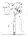
- FIG. 13 provides a similar view to that provided by FIG. 12 , with the addition of a portion of the seating rail;
- FIG. 14 provides a detailed cross-sectional view of a different portion of the battery pack and body/pack cross-members.
- battery may be used interchangeably and may refer to any of a variety of different cell types, chemistries and configurations including, but not limited to, lithium ion (e.g., lithium iron phosphate, lithium cobalt oxide, other lithium metal oxides, etc.), lithium ion polymer, nickel metal hydride, nickel cadmium, nickel hydrogen, nickel zinc, silver zinc, or other battery type/configuration.
- lithium ion e.g., lithium iron phosphate, lithium cobalt oxide, other lithium metal oxides, etc.
- lithium ion polymer lithium ion polymer
- nickel metal hydride nickel cadmium
- nickel hydrogen nickel zinc
- silver zinc or other battery type/configuration
- battery pack refers to multiple individual batteries contained within an enclosure, the individual batteries electrically interconnected to achieve the desired voltage and capacity for a particular application.
- the terms “battery pack” and “battery pack enclosure” may be used interchangeably herein.
- electric vehicle may refer to an all-electric vehicle, also referred to as an EV, a plug-in hybrid vehicle, also referred to as a PHEV, or a hybrid vehicle, also referred to as a HEV, where a hybrid vehicle refers to a vehicle utilizing multiple propulsion sources one of which is an electric drive system.
- a battery pack 101 is mounted under the floor panel of an electric vehicle 100 .
- the battery pack is integrated within the vehicle's structural frame, thus utilizing the battery pack's inherent rigidity and strength to enhance the overall performance and impact resistance of vehicle 100 .
- battery pack 101 not only transverses the width of the vehicle, i.e., from rocker panel to rocker panel, but also extends most of the distance between the front suspension 201 and the rear suspension 203 . It will be appreciated that while smaller battery packs mounted under the vehicle's floor panel(s) may be used with the invention, such smaller packs will typically not provide the same level of vehicle performance enhancement as that provided by the preferred battery pack.
- battery pack 101 is approximately 2.7 meters long and 1.5 meters wide and has a thickness that varies between approximately 0.1 meters to 0.18 meters, the thicker dimension applicable to those portions of the battery pack in which battery modules are stacked one on top of another.
- battery pack 101 is configured to transverse the width of the vehicle and be coupled to the rocker panels located on either side of the vehicle.
- FIG. 4 illustrates an exemplary technique for attaching battery pack 101 to rocker panel 401 , this figure showing the location of battery pack 101 under vehicle floor panel 403 .
- rocker 401 is extruded, for example using an aluminum or aluminum alloy extrusion as described in detail in co-pending U.S. patent application Ser. No. 13/308,206, filed 30 Nov. 2011, and attached to the battery pack as described in co-pending U.S. patent application Ser. No. 13/308,300, filed 30 Nov. 2011, the disclosures of which are incorporated herein for any and all purposes.
- battery pack enclosure 101 includes side members 405 that include a mounting flange.
- the mounting flange is an extended mounting region 407 that is positioned under rocker 401 .
- Region 407 is perforated in order to allow passage of a plurality of mounting bolts 409 .
- Mounting bolts 409 in combination with nuts 411 , mechanically couple extended region 407 of battery pack 101 to rocker 401 .
- channel nuts 411 are held in place during vehicle assembly using a channel nut retainer 413 .
- Retainer 413 is positioned within rocker 401 using internal feature 415 , thereby simplifying vehicle assembly and reducing manufacturing costs. It will be understood that other techniques may be used to mount the battery pack under the vehicle's floor panel.
- FIG. 5 provides a perspective view of battery pack 101 with the top enclosure panel 501 in place, panel 501 preferably providing a substantially airtight seal.
- Side structural elements 405 which are preferably hollow or include multiple cavities, are also visible as is battery pack mounting flange 407 that is used to mechanically and thermally couple the battery pack enclosure to the vehicle structure (not shown in this figure).
- a plurality of mounts 503 is shown, mounts 503 being used to couple the seat assemblies to internal battery pack cross-members as described below.
- FIG. 6 shows battery pack 101 with top panel member 501 removed, this view showing multiple cross-members 601 A- 601 H.
- the number of cross-members is based on the number of cells/cell modules that are to be contained within the battery pack as well as the desired structural characteristics of the battery pack.
- battery pack side members 405 including extended regions 407 , battery pack top panel 501 , battery pack bottom panel 603 and cross-members 601 A- 601 H are each fabricated from a light weight metal, such as aluminum or an aluminum alloy, although other materials such as steel may be used for some or all of the battery pack components.
- Bottom panel 603 may be welded, brazed, soldered, bonded or otherwise attached to side members 405 , with the resultant joint between panel 603 and member 405 preferably being substantially air-tight as well as being strong enough to allow bottom panel 603 to support the batteries contained within the pack.
- Top panel 501 is typically attached to members 405 using bolts or similar means, thus simplifying battery replacement as well as allowing battery interconnects, battery pack components, cooling system components and other battery pack components to be repaired and/or replaced.
- Battery pack cross-members 601 A- 601 H provide several benefits. First and foremost, cross-members 601 A- 601 H provide mechanical and structural strength and rigidity to the battery pack, to the vehicle to which the battery pack is attached, and to the seat mount assemblies which are coupled to the battery pack and the battery pack cross-members. Additionally, cross-members 601 A- 601 H help to segregate battery thermal events by providing a thermal barrier between groups of cells as well as minimizing gas flow between sections 605 , sections 605 being defined by the battery pack cross-members, side members 405 , top member 501 and bottom member 603 . By segregating thermal events within smaller groups of cells, thermal runaway propagation is limited as is the potential for battery pack damage.
- FIG. 7 shows a similar view to that provided by FIG. 6 , with the inclusion of a couple of cell modules 701 .
- a single module 701 is shown positioned within one of the seven, larger sections 605 of battery pack 101 .
- each large section 605 is designed to house a pair of battery pack modules 701 .
- each module 701 contains 370 individual cells, each cell utilizing an 18650 form factor.
- FIG. 8 provides a perspective view of a single module 701 , this view highlighting the module mounting flange 801 .
- mounting flanges 801 are located on either side of the module and, during battery pack assembly, are captured between upper and lower sections of each cross-member.
- FIG. 9 shows the previously illustrated battery module with the upper portion of module 701 removed as well as several of the upper module components (e.g., cell locator plate, current collector plate, etc.), thus making the individual cells 901 visible. Note that the orientation of cells 901 within module 701 varies.
- FIG. 10 provides a perspective, cross-sectional view of battery pack 101 mounted under floor panel 403 of vehicle 100 . This view also provides additional views of the cross-members. Note that in this figure the batteries/battery modules are not shown within the battery pack, thus simplifying the figure in order to better illustrate the basic battery pack/vehicle assembly and configuration.
- battery pack cross-members 601 A- 601 H do not utilize the same cross-section; rather the cross-section of each is optimized for that particular member's location within the pack.
- battery pack cross-members 601 A- 601 H may either be comprised of a single unit or as preferred, comprised of an upper section and a lower section, thus providing a convenient means of capturing and mounting the battery modules 701 .
- One or both sections of each cross-member may be hollow, thus minimizing weight while still providing a rigid and strong structural member. It should be understood that not only can the configuration/design of the cross-members vary, depending upon their location within the pack, so can the materials comprising the cross-members.
- cross-members 601 A- 601 H are preferably fabricated from aluminum or an aluminum alloy, for example using an extrusion process, other materials (e.g., steel, ceramics, etc.) may also be used if such materials fit both the mechanical and thermal goals for the particular cross-member in question.
- the lumens within one or more of the cross-members may be unfilled or filled, for example filled with a high melting temperature, low thermal conductivity material (e.g., fiberglass or similar material).
- the lumens within the cross-members may include a liquid (e.g., water), the liquid being either stagnant or flowing. If stagnant, the liquid may be contained within the lumens themselves or, as preferred, contained within pouches that fit within the cavities. If the liquid is flowing, it is preferably contained within tubing that is inserted within the cross-member cavities and either coupled to a battery cooling system or used in a stand-alone circulation system.
- cross-members 601 D and 601 E are larger than the other central cross-members.
- the reason for the increased size for these particular cross-members is to provide additional cross-member strength at those locations that are both used for seat mounting assemblies and are considered critical to resisting side impact loads that may be encountered during a collision.
- FIG. 11 provides a detailed perspective view of the primary mechanical structural elements of the underbody 1100 .
- This view shows the three body cross-members 1101 - 1103 to which the seat assemblies are attached.
- Body cross-members 1101 - 1103 are preferably welded to side sills 401 .
- front seat rails 1105 are attached to body cross-members 1101 and 1102 .
- the rear seat bench assembly is attached to body cross-member 1103 utilizing a plurality of structural members 1107 .
- the rear seat bench assembly is also attached to the rear torque box.
- the body cross-members are mechanically coupled to the battery pack cross-members as described below. Enhancing the strength and rigidity of the body cross-members, especially at locations adjacent to the seat mounts, dramatically enhances the performance of the seat assemblies. Additionally, the disclosed assembly provides a convenient means of providing further support to the middle of battery pack 101 , specifically by mechanically coupling the battery pack and the internal battery pack cross-members contained therein to the body cross-members that are preferably welded to the vehicle side sills.
- FIGS. 12 and 13 illustrate the preferred approach to mechanically coupling the body cross-members to the battery pack in order to enhance body cross-member strength and rigidity. It should be understood, however, that this is simply one approach to coupling the body cross-members to the underlying battery pack 101 and that other methods are clearly anticipated by the inventors.
- FIG. 12 is a cross-sectional view of a portion of the battery pack 101 , cross-member 1102 and a portion of the vehicle floor panel 403 .
- FIG. 13 provides a similar view with the addition of a portion of a seating rail 1105 .
- FIG. 14 provides a different view of the battery pack and body/pack cross-members.
- each battery pack cross-member 601 A- 601 H is preferably comprised of an upper member 1201 and a lower member 1203 .
- upper member 1201 is attached to battery pack top panel 501 and includes a single lumen 1401
- lower member 1203 is attached to battery pack bottom panel 603 and includes a pair of lumens 1403 and 1405 .
- the lumens also referred to herein as cavities
- the use of upper and lower members for each of the battery pack cross-members 601 A- 601 H provides a convenient means for holding the battery modules in place, specifically by capturing the module mounting flanges 801 within region 1407 during battery pack assembly.
- a sleeve 1205 is inserted into the battery pack, sleeve 1205 passing through the battery pack cross-member as shown.
- Sleeve 1205 which is preferably fabricated from aluminum, an aluminum alloy or steel, provides additional strength to the mount as well as providing a convenient method of providing a seal to insure that water, debris or other contaminants do not enter into the battery pack at the mounting location.
- Sleeve 1205 may be welded, brazed, soldered, bonded or otherwise attached to bottom battery pack panel 603 .
- a spacer 1207 is located on the upper portion of sleeve 1205 .
- spacer 1207 is used to properly locate body cross-member 1102 relative to the top panel 501 of battery pack 101 . Additionally, spacer 1207 may be threaded onto the upper portion of sleeve 1205 . Alternately, spacer 1207 may be mechanically coupled to top battery pack panel 501 , for example via welding, brazing, soldering or bonding. Regardless of the means used to mechanically couple spacer 1207 to the assembly, preferably it provides an upper assembly seal to insure that water, debris or other contaminants do not enter into the battery pack at the body cross-member mount.
- Bolt 1209 is inserted through sleeve 1205 from under battery pack 101 .
- the body cross-member i.e., member 1102 in the illustrated embodiment, is mechanically coupled to the battery pack in general, and the battery pack cross-members in particular, using a nut 1211 with bolt 1209 .
- nut 1211 is held in place by a retaining member 1409 .
- a threaded sleeve 1213 is coupled to the body cross-member, e.g., cross-member 1102 , for example via welding, brazing, soldering or bonding.
- seat rail 1105 is bolted to the body cross-member in general, and mounting sleeve 1213 in particular, using bolt 1301 .
- vehicle floor panels 403 are mounted on top of body cross-member flanges 1215 .
- Floor panels 403 are preferably bonded and riveted to body cross-member flanges 1215 although other means of coupling the two may be used (e.g., welding, brazing, soldering, bolting, etc.).
- vehicle seat belts are also attached to the body cross-members and therefore indirectly attached to the battery pack cross-members.
- vehicle seat belts may be attached to the seat mounting assemblies, and therefore indirectly attached to both the body cross-members and the battery pack cross-members.
Landscapes
- Engineering & Computer Science (AREA)
- Mechanical Engineering (AREA)
- Transportation (AREA)
- Chemical & Material Sciences (AREA)
- Combustion & Propulsion (AREA)
- Sustainable Development (AREA)
- Life Sciences & Earth Sciences (AREA)
- Sustainable Energy (AREA)
- Power Engineering (AREA)
- Aviation & Aerospace Engineering (AREA)
- Arrangement Or Mounting Of Propulsion Units For Vehicles (AREA)
- Battery Mounting, Suspending (AREA)
- Body Structure For Vehicles (AREA)
Abstract
Description
Claims (23)
Priority Applications (2)
| Application Number | Priority Date | Filing Date | Title |
|---|---|---|---|
| US13/328,615 US8336658B2 (en) | 2010-12-22 | 2011-12-16 | Augmented vehicle seat mount |
| US13/986,234 USRE44994E1 (en) | 2010-12-22 | 2013-04-16 | Augmented vehicle seat mount |
Applications Claiming Priority (3)
| Application Number | Priority Date | Filing Date | Title |
|---|---|---|---|
| US201061426254P | 2010-12-22 | 2010-12-22 | |
| US13/308,300 US20120161472A1 (en) | 2010-12-22 | 2011-11-30 | System for Absorbing and Distributing Side Impact Energy Utilizing an Integrated Battery Pack |
| US13/328,615 US8336658B2 (en) | 2010-12-22 | 2011-12-16 | Augmented vehicle seat mount |
Related Parent Applications (1)
| Application Number | Title | Priority Date | Filing Date |
|---|---|---|---|
| US13/308,300 Continuation-In-Part US20120161472A1 (en) | 2010-12-22 | 2011-11-30 | System for Absorbing and Distributing Side Impact Energy Utilizing an Integrated Battery Pack |
Related Child Applications (1)
| Application Number | Title | Priority Date | Filing Date |
|---|---|---|---|
| US13/986,234 Reissue USRE44994E1 (en) | 2010-12-22 | 2013-04-16 | Augmented vehicle seat mount |
Publications (2)
| Publication Number | Publication Date |
|---|---|
| US20120161429A1 US20120161429A1 (en) | 2012-06-28 |
| US8336658B2 true US8336658B2 (en) | 2012-12-25 |
Family
ID=46315692
Family Applications (2)
| Application Number | Title | Priority Date | Filing Date |
|---|---|---|---|
| US13/328,615 Ceased US8336658B2 (en) | 2010-12-22 | 2011-12-16 | Augmented vehicle seat mount |
| US13/986,234 Active USRE44994E1 (en) | 2010-12-22 | 2013-04-16 | Augmented vehicle seat mount |
Family Applications After (1)
| Application Number | Title | Priority Date | Filing Date |
|---|---|---|---|
| US13/986,234 Active USRE44994E1 (en) | 2010-12-22 | 2013-04-16 | Augmented vehicle seat mount |
Country Status (1)
| Country | Link |
|---|---|
| US (2) | US8336658B2 (en) |
Cited By (28)
| Publication number | Priority date | Publication date | Assignee | Title |
|---|---|---|---|---|
| US20110240386A1 (en) * | 2010-04-05 | 2011-10-06 | Coda Automotive, Inc. | Electric vehicle with structurally integrated components |
| US20120160584A1 (en) * | 2010-12-28 | 2012-06-28 | Nitawaki Kunihiro | Electric vehicle |
| US20140014428A1 (en) * | 2012-07-13 | 2014-01-16 | Mitsubishi Jidosha Kogyo Kabushiki Kaisha | Battery pack tray |
| US20140196963A1 (en) * | 2011-07-29 | 2014-07-17 | Renault S.A.S. | Device for attaching a power plant to a chassis of a motor vehicle |
| US20140246259A1 (en) * | 2011-10-07 | 2014-09-04 | Automotive Energy Supply Corporation | Battery pack for driving electric vehicle |
| WO2018192913A1 (en) | 2017-04-20 | 2018-10-25 | Bayerische Motoren Werke Aktiengesellschaft | Assembly for securing a vehicle battery on a body of a motor vehicle, and method for mounting a vehicle battery in a motor vehicle |
| WO2018212161A1 (en) * | 2017-05-18 | 2018-11-22 | 本田技研工業株式会社 | Vehicle body lower structure |
| JP2018192939A (en) * | 2017-05-18 | 2018-12-06 | 本田技研工業株式会社 | Lower body structure |
| JP2018193003A (en) * | 2017-05-19 | 2018-12-06 | 本田技研工業株式会社 | Lower body structure |
| US10207573B2 (en) * | 2016-04-21 | 2019-02-19 | Toyota Jidosha Kabushiki Kaisha | Battery mounting structure for vehicle |
| US20190092395A1 (en) * | 2017-09-25 | 2019-03-28 | Ford Global Technologies, Llc | Vehicle frame assembly |
| US20190217695A1 (en) * | 2018-01-15 | 2019-07-18 | Magna Steyr Fahrzeugtechnik Ag & Co Kg | Vehicle with Supporting Structure |
| DE102018211469A1 (en) * | 2018-07-11 | 2020-01-16 | Audi Ag | battery case |
| US10547039B2 (en) * | 2017-11-17 | 2020-01-28 | Toyota Jidosha Kabushiki Kaisha | Battery case for vehicle and method of manufacturing of battery case |
| WO2020025256A1 (en) | 2018-08-03 | 2020-02-06 | Bayerische Motoren Werke Aktiengesellschaft | Assembly for securing a vehicle battery on a body of a motor vehicle, and method for mounting a vehicle battery in a motor vehicle |
| US10597083B2 (en) * | 2016-09-07 | 2020-03-24 | Thunder Power Electric Vehicle Limited | Placement of battery elements in tunnel |
| WO2020109305A1 (en) * | 2018-11-30 | 2020-06-04 | Bayerische Motoren Werke Aktiengesellschaft | Central connector for vehicles having a high-voltage accumulator |
| US20200262491A1 (en) * | 2019-02-18 | 2020-08-20 | GM Global Technology Operations LLC | Body rocker, battery cross-bar, and body cross-bar configuration for load distribution between vehicle body and under-vehicle battery |
| US20210387550A1 (en) * | 2020-06-15 | 2021-12-16 | Hyundai Motor Company | Vehicle floor structure |
| US11220169B2 (en) * | 2018-12-27 | 2022-01-11 | Ferrari S.P.A. | Electric or hybrid sport car |
| US11370287B2 (en) * | 2017-05-22 | 2022-06-28 | Honda Motor Co., Ltd. | Vehicle body substructure |
| US20230145164A1 (en) * | 2021-11-09 | 2023-05-11 | Hyundai Motor Company | Vehicle Floor System |
| US20230202579A1 (en) * | 2021-12-27 | 2023-06-29 | Hyundai Motor Company | Rear Vehicle Body Structure |
| US20230264755A1 (en) * | 2022-02-24 | 2023-08-24 | Mazda Motor Corporation | Vehicle-body front structure including a reinforcement structure with a rear portion mounted to a floor panel |
| US20230264751A1 (en) * | 2022-02-24 | 2023-08-24 | Mazda Motor Corporation | Vehicle-body front structure |
| US20230264746A1 (en) * | 2022-02-24 | 2023-08-24 | Mazda Motor Corporation | Vehicle-body front structure including side frame protrusions |
| US20230264562A1 (en) * | 2022-02-24 | 2023-08-24 | Mazda Motor Corporation | Vehicle-body structure |
| US12312010B2 (en) * | 2022-02-24 | 2025-05-27 | Mazda Motor Corporation | Vehicle-body front structure |
Families Citing this family (45)
| Publication number | Priority date | Publication date | Assignee | Title |
|---|---|---|---|---|
| DE102005022367B4 (en) * | 2005-05-10 | 2021-05-20 | Sew-Eurodrive Gmbh & Co Kg | Contactlessly supplied consumer and system |
| FR2957888B1 (en) * | 2010-03-29 | 2012-03-23 | Renault Sa | VEHICLE AND SUPPORT FOR ENERGY TANK |
| US8875828B2 (en) | 2010-12-22 | 2014-11-04 | Tesla Motors, Inc. | Vehicle battery pack thermal barrier |
| US8286743B2 (en) | 2010-12-22 | 2012-10-16 | Tesla Motors, Inc. | Vehicle battery pack ballistic shield |
| US20120161472A1 (en) | 2010-12-22 | 2012-06-28 | Tesla Motors, Inc. | System for Absorbing and Distributing Side Impact Energy Utilizing an Integrated Battery Pack |
| US8696051B2 (en) | 2010-12-22 | 2014-04-15 | Tesla Motors, Inc. | System for absorbing and distributing side impact energy utilizing a side sill assembly with a collapsible sill insert |
| DE102011112572A1 (en) | 2011-09-08 | 2013-03-14 | GM Global Technology Operations LLC (n. d. Gesetzen des Staates Delaware) | Replaceable battery module for an electric vehicle |
| JP5925290B2 (en) * | 2012-02-29 | 2016-05-25 | 住友重機械工業株式会社 | Excavator |
| EP2662230B1 (en) * | 2012-05-08 | 2018-01-24 | Magna Steyr Fahrzeugtechnik AG & Co KG | Battery casing |
| JP5971234B2 (en) * | 2013-12-25 | 2016-08-17 | トヨタ自動車株式会社 | Resin panel structure |
| DE102015007960A1 (en) * | 2015-06-20 | 2016-12-22 | Audi Ag | Battery housing for a motor vehicle and method for sealing a battery housing for a motor vehicle |
| US9688164B2 (en) | 2015-08-25 | 2017-06-27 | Tesla, Inc. | Movable vehicle seat with monopost |
| US9669734B2 (en) | 2015-08-27 | 2017-06-06 | Tesla, Inc. | Monopost for free-standing vehicle seat |
| JP6332250B2 (en) * | 2015-12-07 | 2018-05-30 | トヨタ自動車株式会社 | Vehicle floor structure |
| DE102016212273A1 (en) * | 2016-07-05 | 2018-01-11 | Bayerische Motoren Werke Aktiengesellschaft | Electrical energy storage for a motor vehicle |
| US10549620B2 (en) | 2016-09-07 | 2020-02-04 | Thunder Power Electric Vehicle Limited | Profiles in the floor section |
| JP6555235B2 (en) * | 2016-11-30 | 2019-08-07 | トヨタ自動車株式会社 | Lower body structure |
| KR102474370B1 (en) * | 2018-01-08 | 2022-12-05 | 현대자동차 주식회사 | Side vehicle body reinforcing structure |
| CN110027622A (en) * | 2018-01-12 | 2019-07-19 | 丰田自动车株式会社 | Lower vehicle construction |
| JP7110648B2 (en) * | 2018-03-22 | 2022-08-02 | トヨタ自動車株式会社 | vehicle |
| FR3081261B1 (en) * | 2018-05-18 | 2020-04-24 | Faurecia Systemes D'echappement | BATTERY AND VEHICLE EQUIPPED WITH SUCH A BATTERY |
| CN108598324A (en) * | 2018-06-05 | 2018-09-28 | 华霆(合肥)动力技术有限公司 | Battery case and electric vehicle |
| US10882426B2 (en) * | 2018-08-20 | 2021-01-05 | Ford Global Technologies, Llc | Vehicle seat belt system |
| JP7044013B2 (en) * | 2018-08-27 | 2022-03-30 | トヨタ自動車株式会社 | Vehicle undercarriage |
| JP7029374B2 (en) | 2018-09-27 | 2022-03-03 | 本田技研工業株式会社 | Vehicle structure |
| JP7059918B2 (en) | 2018-12-18 | 2022-04-26 | トヨタ自動車株式会社 | Vehicle battery case structure |
| KR102645055B1 (en) * | 2019-04-10 | 2024-03-08 | 현대자동차주식회사 | Vehicle center floor structure |
| DE102019207486B4 (en) * | 2019-05-22 | 2021-03-11 | Volkswagen Aktiengesellschaft | Body floor structure for a vehicle |
| DE102019123844A1 (en) * | 2019-09-05 | 2021-03-11 | Bayerische Motoren Werke Aktiengesellschaft | Vehicle floor for an energy storage floor assembly of a motor vehicle |
| DE102019123845A1 (en) * | 2019-09-05 | 2021-03-11 | Bayerische Motoren Werke Aktiengesellschaft | Energy storage floor pan for a motor vehicle |
| JP7240298B2 (en) | 2019-10-11 | 2023-03-15 | 株式会社神戸製鋼所 | Method for manufacturing battery case for electric vehicle and battery case for electric vehicle |
| MX2022008267A (en) | 2020-01-03 | 2022-08-04 | Tesla Inc | Selective extraction of lithium from clay minerals. |
| JP7231572B2 (en) * | 2020-01-17 | 2023-03-01 | トヨタ自動車株式会社 | Underbody structure |
| US12172510B2 (en) | 2020-08-03 | 2024-12-24 | Hyundai Motor Company | High voltage battery mounting structure for a vehicle |
| KR102898365B1 (en) | 2020-08-03 | 2025-12-09 | 현대자동차주식회사 | Battery-equipped body |
| KR20220016658A (en) | 2020-08-03 | 2022-02-10 | 현대자동차주식회사 | High voltage battery mounting structure for vehicle |
| US12172511B2 (en) | 2020-08-03 | 2024-12-24 | Hyundai Motor Company | Vehicle body having battery support arrangement |
| KR20220026384A (en) | 2020-08-25 | 2022-03-04 | 현대자동차주식회사 | Battery-equipped body |
| KR20220048785A (en) * | 2020-10-13 | 2022-04-20 | 현대자동차주식회사 | Body for vehicle |
| KR20220085133A (en) | 2020-12-15 | 2022-06-22 | 현대자동차주식회사 | Side sill for mounting sliding door of vehicle |
| EP4015352B1 (en) * | 2020-12-17 | 2025-10-01 | Volvo Car Corporation | Motor vehicle with a combined scalable platform for either an internal combustion engine or a battery-powered electric vehicle |
| SE2150957A1 (en) * | 2021-07-16 | 2023-01-17 | Nat Electric Vehicle Sweden Ab | Structural Rechargeable Electric Energy Storage System |
| KR102621565B1 (en) | 2022-03-07 | 2024-01-04 | 현대자동차주식회사 | Vehicle under structure for mounting a battery |
| KR20240022837A (en) * | 2022-08-12 | 2024-02-20 | 현대자동차주식회사 | Floor structure for electric vehicle |
| FR3153065A1 (en) * | 2023-09-20 | 2025-03-21 | Psa Automobiles Sa | Underbody assembly for a motor vehicle with a battery pack fixed under its front floor |
Citations (22)
| Publication number | Priority date | Publication date | Assignee | Title |
|---|---|---|---|---|
| US4262963A (en) | 1979-05-21 | 1981-04-21 | C. Rob. Hammerstein Gmbh | Guide rail assembly for a vehicle seat |
| US4526424A (en) | 1982-05-14 | 1985-07-02 | P.A. Rentrop Hubbert & Wagner Fahrzeugausstattungen Gmbh & Co. Kg | Slide rail assembly for a vehicle seat |
| US4784434A (en) | 1987-04-24 | 1988-11-15 | Tachi-S Co. | Vehicle seat with suspension device |
| US4818022A (en) | 1985-12-09 | 1989-04-04 | Nissan Motor Co., Ltd. | Seat belt anchor-equipped seat slide device |
| US5322348A (en) | 1991-07-10 | 1994-06-21 | Douglas & Lomason Company | Automotive seat adjustment mechanism with traveling seat belt buckle arrangement |
| US5392873A (en) * | 1992-01-22 | 1995-02-28 | Honda Giken Kogyo Kabushiki Kaisha | Structure for securing batteries used in an electric vehicle |
| US5639571A (en) * | 1996-06-24 | 1997-06-17 | General Motors Corporation | Battery pack |
| US5653506A (en) | 1995-08-25 | 1997-08-05 | Track Corp. | Automotive seat recliner interlock |
| US5672920A (en) * | 1996-05-02 | 1997-09-30 | Chrysler Corporation | Current sharing AC Bus Bar |
| US6094927A (en) * | 1997-12-18 | 2000-08-01 | Honda Giken Kogyo Kabushiki Kaisha | Cooling structure an electric vehicle |
| US6811186B1 (en) | 2002-03-29 | 2004-11-02 | Lear Corporation | Seat belt adjustment mechanism |
| US7048321B2 (en) * | 2003-05-21 | 2006-05-23 | Honda Motor Co., Ltd. | High-voltage electrical equipment case arranging structure |
| US7066521B2 (en) | 2004-02-23 | 2006-06-27 | Das Co., Ltd. | Locking guide of seat locking device for vehicle |
| US7128999B1 (en) * | 2000-03-13 | 2006-10-31 | General Motors Corporation | System of retaining a plurality of batteries for an electric/hybrid vehicle |
| US20070238016A1 (en) * | 2006-04-10 | 2007-10-11 | Nissan Motor Co., Ltd. | Battery pack |
| US7507499B2 (en) * | 2004-05-24 | 2009-03-24 | General Motors Corporation | Battery pack arrangements |
| US20090186266A1 (en) * | 2007-09-28 | 2009-07-23 | Haruchika Nishino | Battery unit |
| US20090242299A1 (en) * | 2007-09-28 | 2009-10-01 | Mitsubishi Jidosha Kogyo Kabushiki Kaisha | Electric vehicle |
| US7654352B2 (en) * | 2007-12-05 | 2010-02-02 | Mitsubishi Jidosha Kogyo Kabushiki Kaisha | Electric vehicle |
| US20100175940A1 (en) * | 2007-09-28 | 2010-07-15 | Mitsubishi Jidosha Kogyo Kabushiki Kaisha | Battery positioning structure for electric vehicle |
| US7780230B2 (en) | 2004-04-30 | 2010-08-24 | Hector Serber | Seat assembly with movable seat and backrest and method |
| US7887094B2 (en) | 2007-06-05 | 2011-02-15 | Mazda Motor Corporation | Seat system |
-
2011
- 2011-12-16 US US13/328,615 patent/US8336658B2/en not_active Ceased
-
2013
- 2013-04-16 US US13/986,234 patent/USRE44994E1/en active Active
Patent Citations (22)
| Publication number | Priority date | Publication date | Assignee | Title |
|---|---|---|---|---|
| US4262963A (en) | 1979-05-21 | 1981-04-21 | C. Rob. Hammerstein Gmbh | Guide rail assembly for a vehicle seat |
| US4526424A (en) | 1982-05-14 | 1985-07-02 | P.A. Rentrop Hubbert & Wagner Fahrzeugausstattungen Gmbh & Co. Kg | Slide rail assembly for a vehicle seat |
| US4818022A (en) | 1985-12-09 | 1989-04-04 | Nissan Motor Co., Ltd. | Seat belt anchor-equipped seat slide device |
| US4784434A (en) | 1987-04-24 | 1988-11-15 | Tachi-S Co. | Vehicle seat with suspension device |
| US5322348A (en) | 1991-07-10 | 1994-06-21 | Douglas & Lomason Company | Automotive seat adjustment mechanism with traveling seat belt buckle arrangement |
| US5392873A (en) * | 1992-01-22 | 1995-02-28 | Honda Giken Kogyo Kabushiki Kaisha | Structure for securing batteries used in an electric vehicle |
| US5653506A (en) | 1995-08-25 | 1997-08-05 | Track Corp. | Automotive seat recliner interlock |
| US5672920A (en) * | 1996-05-02 | 1997-09-30 | Chrysler Corporation | Current sharing AC Bus Bar |
| US5639571A (en) * | 1996-06-24 | 1997-06-17 | General Motors Corporation | Battery pack |
| US6094927A (en) * | 1997-12-18 | 2000-08-01 | Honda Giken Kogyo Kabushiki Kaisha | Cooling structure an electric vehicle |
| US7128999B1 (en) * | 2000-03-13 | 2006-10-31 | General Motors Corporation | System of retaining a plurality of batteries for an electric/hybrid vehicle |
| US6811186B1 (en) | 2002-03-29 | 2004-11-02 | Lear Corporation | Seat belt adjustment mechanism |
| US7048321B2 (en) * | 2003-05-21 | 2006-05-23 | Honda Motor Co., Ltd. | High-voltage electrical equipment case arranging structure |
| US7066521B2 (en) | 2004-02-23 | 2006-06-27 | Das Co., Ltd. | Locking guide of seat locking device for vehicle |
| US7780230B2 (en) | 2004-04-30 | 2010-08-24 | Hector Serber | Seat assembly with movable seat and backrest and method |
| US7507499B2 (en) * | 2004-05-24 | 2009-03-24 | General Motors Corporation | Battery pack arrangements |
| US20070238016A1 (en) * | 2006-04-10 | 2007-10-11 | Nissan Motor Co., Ltd. | Battery pack |
| US7887094B2 (en) | 2007-06-05 | 2011-02-15 | Mazda Motor Corporation | Seat system |
| US20090186266A1 (en) * | 2007-09-28 | 2009-07-23 | Haruchika Nishino | Battery unit |
| US20090242299A1 (en) * | 2007-09-28 | 2009-10-01 | Mitsubishi Jidosha Kogyo Kabushiki Kaisha | Electric vehicle |
| US20100175940A1 (en) * | 2007-09-28 | 2010-07-15 | Mitsubishi Jidosha Kogyo Kabushiki Kaisha | Battery positioning structure for electric vehicle |
| US7654352B2 (en) * | 2007-12-05 | 2010-02-02 | Mitsubishi Jidosha Kogyo Kabushiki Kaisha | Electric vehicle |
Cited By (54)
| Publication number | Priority date | Publication date | Assignee | Title |
|---|---|---|---|---|
| US20110240386A1 (en) * | 2010-04-05 | 2011-10-06 | Coda Automotive, Inc. | Electric vehicle with structurally integrated components |
| US20120160584A1 (en) * | 2010-12-28 | 2012-06-28 | Nitawaki Kunihiro | Electric vehicle |
| US8789634B2 (en) * | 2010-12-28 | 2014-07-29 | Suzuki Motor Corporation | Electric vehicle |
| US20140196963A1 (en) * | 2011-07-29 | 2014-07-17 | Renault S.A.S. | Device for attaching a power plant to a chassis of a motor vehicle |
| US20140246259A1 (en) * | 2011-10-07 | 2014-09-04 | Automotive Energy Supply Corporation | Battery pack for driving electric vehicle |
| US20140014428A1 (en) * | 2012-07-13 | 2014-01-16 | Mitsubishi Jidosha Kogyo Kabushiki Kaisha | Battery pack tray |
| US8967312B2 (en) * | 2012-07-13 | 2015-03-03 | Mitsubishi Jidosha Kogyo Kabushiki Kaisha | Battery pack tray |
| US10207573B2 (en) * | 2016-04-21 | 2019-02-19 | Toyota Jidosha Kabushiki Kaisha | Battery mounting structure for vehicle |
| US10597083B2 (en) * | 2016-09-07 | 2020-03-24 | Thunder Power Electric Vehicle Limited | Placement of battery elements in tunnel |
| WO2018192913A1 (en) | 2017-04-20 | 2018-10-25 | Bayerische Motoren Werke Aktiengesellschaft | Assembly for securing a vehicle battery on a body of a motor vehicle, and method for mounting a vehicle battery in a motor vehicle |
| DE102017206650A1 (en) | 2017-04-20 | 2018-10-25 | Bayerische Motoren Werke Aktiengesellschaft | Fastening arrangement for a vehicle battery on a body of a motor vehicle and method for mounting a vehicle battery in a motor vehicle |
| US11691492B2 (en) | 2017-04-20 | 2023-07-04 | Bayerische Motoren Werke Aktiengesellschaft | Assembly for securing a vehicle battery on a body of a motor vehicle, and method for mounting a vehicle battery in a motor vehicle |
| JP2018192939A (en) * | 2017-05-18 | 2018-12-06 | 本田技研工業株式会社 | Lower body structure |
| CN110650886A (en) * | 2017-05-18 | 2020-01-03 | 本田技研工业株式会社 | Vehicle body lower structure |
| CN110650886B (en) * | 2017-05-18 | 2022-03-15 | 本田技研工业株式会社 | Body Substructure |
| WO2018212161A1 (en) * | 2017-05-18 | 2018-11-22 | 本田技研工業株式会社 | Vehicle body lower structure |
| JP2018193003A (en) * | 2017-05-19 | 2018-12-06 | 本田技研工業株式会社 | Lower body structure |
| US11370287B2 (en) * | 2017-05-22 | 2022-06-28 | Honda Motor Co., Ltd. | Vehicle body substructure |
| US20190092395A1 (en) * | 2017-09-25 | 2019-03-28 | Ford Global Technologies, Llc | Vehicle frame assembly |
| US10494034B2 (en) * | 2017-09-25 | 2019-12-03 | Ford Global Technologies, Llc | Vehicle frame assembly |
| US10988186B2 (en) | 2017-09-25 | 2021-04-27 | Ford Global Technologies, Llc | Vehicle frame assembly |
| US10547039B2 (en) * | 2017-11-17 | 2020-01-28 | Toyota Jidosha Kabushiki Kaisha | Battery case for vehicle and method of manufacturing of battery case |
| US20190217695A1 (en) * | 2018-01-15 | 2019-07-18 | Magna Steyr Fahrzeugtechnik Ag & Co Kg | Vehicle with Supporting Structure |
| US10661647B2 (en) * | 2018-01-15 | 2020-05-26 | Magna Steyr Fahrzeugtechnik Ag & Co Kg | Vehicle with supporting structure |
| DE102018211469A1 (en) * | 2018-07-11 | 2020-01-16 | Audi Ag | battery case |
| US11760181B2 (en) | 2018-08-03 | 2023-09-19 | Bayerische Motoren Werke Aktiengesellschaft | Assembly for securing a vehicle battery on a body of a motor vehicle and method for mounting a vehicle battery in a motor vehicle |
| WO2020025256A1 (en) | 2018-08-03 | 2020-02-06 | Bayerische Motoren Werke Aktiengesellschaft | Assembly for securing a vehicle battery on a body of a motor vehicle, and method for mounting a vehicle battery in a motor vehicle |
| US11858329B2 (en) | 2018-11-30 | 2024-01-02 | Bayerische Motoren Werke Aktiengesellschaft | Central connector for vehicles having a high-voltage accumulator |
| WO2020109305A1 (en) * | 2018-11-30 | 2020-06-04 | Bayerische Motoren Werke Aktiengesellschaft | Central connector for vehicles having a high-voltage accumulator |
| US11220169B2 (en) * | 2018-12-27 | 2022-01-11 | Ferrari S.P.A. | Electric or hybrid sport car |
| US10822039B2 (en) * | 2019-02-18 | 2020-11-03 | GM Global Technology Operations LLC | Body rocker, battery cross-bar, and body cross-bar configuration for load distribution between vehicle body and under-vehicle battery |
| US20200262491A1 (en) * | 2019-02-18 | 2020-08-20 | GM Global Technology Operations LLC | Body rocker, battery cross-bar, and body cross-bar configuration for load distribution between vehicle body and under-vehicle battery |
| US20210387550A1 (en) * | 2020-06-15 | 2021-12-16 | Hyundai Motor Company | Vehicle floor structure |
| US11524606B2 (en) * | 2020-06-15 | 2022-12-13 | Hyundai Motor Company | Vehicle floor structure |
| US20230145164A1 (en) * | 2021-11-09 | 2023-05-11 | Hyundai Motor Company | Vehicle Floor System |
| US12280649B2 (en) * | 2021-11-09 | 2025-04-22 | Hyundai Motor Company | Vehicle floor system |
| US20230202579A1 (en) * | 2021-12-27 | 2023-06-29 | Hyundai Motor Company | Rear Vehicle Body Structure |
| US11939003B2 (en) * | 2021-12-27 | 2024-03-26 | Hyundai Motor Company | Rear vehicle body structure |
| US20230264746A1 (en) * | 2022-02-24 | 2023-08-24 | Mazda Motor Corporation | Vehicle-body front structure including side frame protrusions |
| US20230264753A1 (en) * | 2022-02-24 | 2023-08-24 | Mazda Motor Corporation | Vehicle-body front structure including a reinforcement structure with a rear portion mounted on an inside-casing structure |
| US20230264562A1 (en) * | 2022-02-24 | 2023-08-24 | Mazda Motor Corporation | Vehicle-body structure |
| US20230264558A1 (en) * | 2022-02-24 | 2023-08-24 | Mazda Motor Corporation | Vehicle-body front structure including reinforcement members |
| US20230264756A1 (en) * | 2022-02-24 | 2023-08-24 | Mazda Motor Corporation | Vehicle-body front structure including a reinforcement structure that couples a motor arrangement portion and a cross structure together |
| US20230264552A1 (en) * | 2022-02-24 | 2023-08-24 | Mazda Motor Corporation | Vehicle-body front structure including a reinforcement structure with a rear portion mounted to a floor panel |
| US20230264557A1 (en) * | 2022-02-24 | 2023-08-24 | Mazda Motor Corporation | Vehicle-body front structure with side frame support |
| US20230264757A1 (en) * | 2022-02-24 | 2023-08-24 | Mazda Motor Corporation | Vehicle-body front structure including a reinforcement structure and a floor reinforcement |
| US20230264559A1 (en) * | 2022-02-24 | 2023-08-24 | Mazda Motor Corporation | Vehicle-body front structure including a cross member |
| US20230264751A1 (en) * | 2022-02-24 | 2023-08-24 | Mazda Motor Corporation | Vehicle-body front structure |
| US20230264755A1 (en) * | 2022-02-24 | 2023-08-24 | Mazda Motor Corporation | Vehicle-body front structure including a reinforcement structure with a rear portion mounted to a floor panel |
| US12312010B2 (en) * | 2022-02-24 | 2025-05-27 | Mazda Motor Corporation | Vehicle-body front structure |
| US12371104B2 (en) * | 2022-02-24 | 2025-07-29 | Mazda Motor Corporation | Vehicle-body front structure |
| US12384467B2 (en) * | 2022-02-24 | 2025-08-12 | Mazda Motor Corporation | Vehicle-body front structure including a reinforcement structure and a floor reinforcement |
| US12428071B2 (en) * | 2022-02-24 | 2025-09-30 | Mazda Motor Corporation | Vehicle-body front structure including a reinforcement structure with a rear portion mounted to a floor panel |
| US12528346B2 (en) * | 2022-02-24 | 2026-01-20 | Mazda Motor Corporation | Vehicle-body front structure including side frame protrusions |
Also Published As
| Publication number | Publication date |
|---|---|
| US20120161429A1 (en) | 2012-06-28 |
| USRE44994E1 (en) | 2014-07-08 |
Similar Documents
| Publication | Publication Date | Title |
|---|---|---|
| US8336658B2 (en) | Augmented vehicle seat mount | |
| US9045030B2 (en) | System for absorbing and distributing side impact energy utilizing an integrated battery pack | |
| US8585131B2 (en) | Rear vehicle torque box | |
| US8702161B2 (en) | System for absorbing and distributing side impact energy utilizing an integrated battery pack and side sill assembly | |
| US8833499B2 (en) | Integration system for a vehicle battery pack | |
| US8875828B2 (en) | Vehicle battery pack thermal barrier | |
| JP7405299B2 (en) | Battery mounting structure | |
| US8424960B2 (en) | Front rail configuration for the front structure of a vehicle | |
| US11485214B2 (en) | Frame-mounted battery enclosure | |
| US20220363122A1 (en) | Under body structure of automobile | |
| US11114722B2 (en) | Vehicle battery module | |
| US20220223965A1 (en) | Battery pack and manufacturing method thereof | |
| CN113320372B (en) | Barrier assembly for energy storage system and vehicle using barrier assembly | |
| US12233700B2 (en) | Structural assembly and vehicle having structural assembly | |
| EP4474186A1 (en) | Structural battery pack | |
| US20240429529A1 (en) | Energy Storage Floor Assembly for a Motor Vehicle, in Particular for a Passenger Car, and Motor Vehicle | |
| US12365390B2 (en) | Structural assembly for vehicle |
Legal Events
| Date | Code | Title | Description |
|---|---|---|---|
| FEPP | Fee payment procedure |
Free format text: PAYOR NUMBER ASSIGNED (ORIGINAL EVENT CODE: ASPN); ENTITY STATUS OF PATENT OWNER: LARGE ENTITY |
|
| AS | Assignment |
Owner name: TESLA MOTORS, INC., CALIFORNIA Free format text: ASSIGNMENT OF ASSIGNORS INTEREST;ASSIGNORS:RAWLINSON, PETER DORE;CLARKE, ALAN PAUL;SIGNING DATES FROM 20111215 TO 20111216;REEL/FRAME:027402/0264 |
|
| STCF | Information on status: patent grant |
Free format text: PATENTED CASE |
|
| AS | Assignment |
Owner name: TESLA MOTORS, INC., CALIFORNIA Free format text: ASSIGNMENT OF ASSIGNORS INTEREST;ASSIGNORS:SUMPF, ROBERT DAVID, JR.;EDWARDS, BRUCE PHILIP;REEL/FRAME:030071/0828 Effective date: 20130103 |
|
| RF | Reissue application filed |
Effective date: 20130415 |
|
| AS | Assignment |
Owner name: TESLA, INC., CALIFORNIA Free format text: CHANGE OF NAME;ASSIGNOR:TESLA MOTORS, INC.;REEL/FRAME:053549/0236 Effective date: 20170201 |