US8335030B2 - Light controlling apparatus, control unit of light controlling apparatus, and method of driving light controlling apparatus - Google Patents
Light controlling apparatus, control unit of light controlling apparatus, and method of driving light controlling apparatus Download PDFInfo
- Publication number
- US8335030B2 US8335030B2 US12/534,688 US53468809A US8335030B2 US 8335030 B2 US8335030 B2 US 8335030B2 US 53468809 A US53468809 A US 53468809A US 8335030 B2 US8335030 B2 US 8335030B2
- Authority
- US
- United States
- Prior art keywords
- light controlling
- incident
- aperture
- controlling unit
- driving force
- Prior art date
- Legal status (The legal status is an assumption and is not a legal conclusion. Google has not performed a legal analysis and makes no representation as to the accuracy of the status listed.)
- Active, expires
Links
Images


Classifications
-
- G—PHYSICS
- G02—OPTICS
- G02B—OPTICAL ELEMENTS, SYSTEMS OR APPARATUS
- G02B26/00—Optical devices or arrangements for the control of light using movable or deformable optical elements
- G02B26/02—Optical devices or arrangements for the control of light using movable or deformable optical elements for controlling the intensity of light
-
- G—PHYSICS
- G02—OPTICS
- G02B—OPTICAL ELEMENTS, SYSTEMS OR APPARATUS
- G02B5/00—Optical elements other than lenses
- G02B5/005—Diaphragms
-
- G—PHYSICS
- G03—PHOTOGRAPHY; CINEMATOGRAPHY; ANALOGOUS TECHNIQUES USING WAVES OTHER THAN OPTICAL WAVES; ELECTROGRAPHY; HOLOGRAPHY
- G03B—APPARATUS OR ARRANGEMENTS FOR TAKING PHOTOGRAPHS OR FOR PROJECTING OR VIEWING THEM; APPARATUS OR ARRANGEMENTS EMPLOYING ANALOGOUS TECHNIQUES USING WAVES OTHER THAN OPTICAL WAVES; ACCESSORIES THEREFOR
- G03B9/00—Exposure-making shutters; Diaphragms
- G03B9/02—Diaphragms
- G03B9/04—Single movable plate with two or more apertures of graded size, e.g. sliding plate or pivoting plate
Definitions
- the present invention relates to a light controlling apparatus, a control unit of the light controlling apparatus, and a method of driving the light controlling apparatus.
- a variety of types have hitherto been implemented as a light controlling apparatus, and as one of the methods, a plug-in type light controlling apparatus in which, a single or a plurality of optical elements is displaced mutually inside and outside an optical path, by an electromagnet or a drive source other than the electromagnet, and optical characteristics of incident light which passes through the optical path are changed, is available.
- a plug-in type light controlling apparatus by forming a plurality of optical elements, it is possible to extend functions thereof.
- optical elements such as a lens, a diaphragm, and an optical filter, a focus lens, a variable diaphragm, and a variable characteristics filter have been increasingly sought to be used rather than the conventional fixed focus lens, fixed diaphragm, and fixed characteristics filter.
- the abovementioned plug-in type light controlling apparatus because of a simple structure, has been drawing attention as a light controlling apparatus which is appropriate for making the size small.
- a light controlling apparatus which includes a plurality of light shielding members which control an amount of light, a plurality of driving means which drive the plurality of light shielding members respectively by acquiring an electromagnetic driving force, and a base member on which, the plurality of light shielding members and the plurality of driving means are installed, and in which, the small-sizing and stable drive of the apparatus are realized by providing an inhibiting member which inhibits an inflow of leakage flux into an intermediate portion of the plurality of driving means has been disclosed.
- the present invention is made in view of the abovementioned circumstances, and an object of the present invention is to provide a light controlling apparatus including a plurality of optical elements, and in which, it is possible to prevent an operation of the light controlling apparatus from becoming unstable due to the mutual effect or interference between the optical elements.
- a method of driving light controlling apparatus which includes a substrate, which has an aperture, a plurality of incident-light controlling unit which are displaced on the substrate, a plurality of driving unit which exert on the incident-light controlling unit, an aperture-displacing diving force which displaces the incident-light controlling unit to an aperture position, and a retracting-displacement driving force which displaces the incident-light controlling unit to a retracted position which is different from the aperture position, the incident-light controlling unit is displaced by the driving unit to the aperture position and the retracted position alternately, and incident light passing through the aperture is adjusted, and the displacement of each incident-light controlling unit to the aperture position is exclusive for the other incident-light controlling unit, including
- a step of displacing the incident-light controlling unit which includes a step of displacing a first incident-light controlling unit disposed at the aperture position, to the retracted position, and a step of displacing a second incident-light controlling unit disposed at the retracted position, to the aperture position, after completion of the step of displacing the first incident-light controlling unit to the retracted position.
- the method of driving light controlling apparatus further includes a step of releasing the retracting-displacement driving force of the driving units corresponding to all the incident-light controlling unit disposed at the retracted position, after completion of the step of displacing the second incident-light controlling unit disposed at the retracted position, to the aperture position.
- the method of driving light controlling apparatus may further include a step of exerting the retracting-displacement driving force of the driving units corresponding to all incident-light controlling unit disposed at the retracted position prior to the step of displacing the first incident-light controlling unit disposed at the aperture position to the retracted position.
- the method of driving light controlling unit according to the present invention can further include a step of reducing the aperture-displacing driving force of the driving unit corresponding to the incident-light controlling unit disposed at the aperture position after the step of displacing the second incident-light controlling unit disposed at the retracted position, to the aperture position.
- the aperture-displacing driving force and the retracting-displacement driving force include an operating driving force which displaces the position of the incident-light controlling unit and a maintaining driving force which maintains the position of the incident-light controlling unit, and that the operating driving force is stronger than the maintaining driving force.
- the operating driving force is in a form of a sinusoidal wave.
- the maintaining driving force can be exerted intermittently to the incident-light controlling unit.
- the plurality of incident-light controlling unit may be displaced in a same plane.
- each of the plurality of incident-light controlling unit is displaced in a different plane, and that a regulating member which regulates the displacement of the other incident-light controlling unit to the aperture position is formed in each incident-light controlling unit.
- all the incident-light controlling unit can be displaced to the retracted position.
- a different optical lens may be formed for each incident-light controlling unit.
- a control unit of light controlling apparatus which drives a light controlling apparatus, generates the aperture-displacing driving force and the retracting-displacement driving force, and exerts the aperture-displacing driving force and the retracting-displacement driving force to the incident-light controlling unit.
- a light controlling apparatus includes
- a plurality of driving unit which exert on the incident-light controlling unit, an aperture-displacing driving force which displaces the incident-light controlling unit to an aperture position, and a retracting-displacement driving force which displaces the incident-light controlling unit to a retracted position which is different from the aperture position, and
- a detecting section which detects a state of the incident-light controlling unit
- the incident-light controlling unit is displaced by the driving unit to the aperture position and the retracted position alternately, and incident light passing through the aperture is adjusted, and the displacement of each incident-light controlling unit to the aperture position is exclusive for the other incident-light controlling unit.
- an aperture of different diameter is formed in each incident-light controlling unit.
- a different optical lens may be formed for each incident-light controlling unit.
- a different optical filter can be formed for each incident-light controlling unit.
- FIG. 1 is an exploded perspective view showing a structure of a multiple-stage variable diaphragm according to a first embodiment of the present invention
- FIG. 2 is a plan view showing an example in which, a torque in a direction toward one position of an aperture is applied to one of a plurality of diaphragm plates according to the first embodiment, and a torque in a direction toward a retracted position is applied to the remaining diaphragm plates according to the first embodiment;
- FIG. 3 is a plan view showing a state of a structure in a basic driving state of the multiple-stage variable diaphragm according to the first embodiment
- FIG. 4 is a graph showing a driving force which acts on a diaphragm plate according to the first embodiment
- FIG. 5 is a plan view showing a state of a structure of the multiple-stage variable diaphragm during a driving state
- FIG. 6A , FIG. 6B , and FIG. 6C are graphs showing a driving force which acts on a plurality of diaphragm plates respectively;
- FIG. 7A is a block diagram showing a structure of a control unit of the multiple-stage variable diaphragm according to the first embodiment
- FIG. 7B is a block diagram showing a structure of a control unit according to a modified embodiment
- FIG. 8 is a plan view showing a structure of a multiple-stage variable diaphragm according to another modified embodiment
- FIG. 9 is a plan view showing a state of a structure of a multiple-stage variable diaphragm during a driving state, in a method of driving a multiple-stage variable diaphragm according to a second embodiment
- FIG. 10A , FIG. 10B , and FIG. 10C are graphs showing a driving force which acts on a plurality of diaphragm plates respectively, in the method of driving multiple-stage variable diaphragm according to the second embodiment of the present invention
- FIG. 11 is a plan view showing a state of a structure of a multiple-stage variable diaphragm during a driving state, in a method of driving a multiple-stage variable diaphragm according to a third embodiment
- FIG. 12A , FIG. 12B , and FIG. 12C are graphs showing a driving force which acts on a plurality of diaphragm plates respectively, in a method of driving multiple-stage variable diaphragm according to the third embodiment of the present invention
- FIG. 13 is a graph showing a driving force which acts on a diaphragm plate of a multiple-stage variable diaphragm according to a fourth embodiment, for displacing the diaphragm plate from a retracted position to a position of an aperture;
- FIG. 14 is a graph showing a driving force which acts on a diaphragm plate of a multiple-stage variable diaphragm according to a fifth embodiment, for displacing the diaphragm plate from the retracted position to the aperture position.
- a light controlling apparatus is a multiple-stage variable diaphragm 100 in which, a plurality of diaphragm plates having different aperture diameter is formed, and which regulates in stages, an amount of light passing through an aperture by displacing each diaphragm plate to an optical-path position and outside the optical path.
- a structure of the multiple-stage variable diaphragm 100 (light controlling apparatus) according to the first embodiment will be described below by referring to FIG. 1 .
- FIG. 1 is an exploded perspective view showing the structure of the multiple-stage variable diaphragm 100 according to the first embodiment.
- the multiple-stage variable diaphragm 100 includes a lower substrate 10 (base plate), a plurality of diaphragm plates 20 a , 20 b , and 20 c (incident-light controlling means), a spacer 30 , an upper substrate 40 (base plate), and a plurality of coils 50 a , 50 b , and 50 c (driving means).
- a first aperture 11 , a plurality of bearing holes 12 a , 12 b , and 12 c , and a plurality of positioning protrusions 13 a , 13 b , and 13 c are formed in the lower substrate 10 .
- Apertures 21 a , 21 b , and 21 c having mutually different diameter, and shaft members 22 a , 22 b , and 22 c are formed in and on the plurality of diaphragm plates 20 a , 20 b , and 20 c respectively.
- An opening portion 31 is formed in the spacer 30 .
- a second aperture 41 and a plurality of bearing holes 42 a , 42 b , and 42 c are formed in the upper substrate 40 .
- coil wires 52 a , 52 b , and 52 c are wound around cores 51 a , 51 b , and 51 c respectively.
- the lower substrate 10 and the upper substrate 40 are disposed such that a center of a circular-shaped opening of the first aperture 11 of the lower substrate 10 and a center of a circular-shaped opening of the second aperture 41 of the upper substrate 40 coincide with an optical axis L, and an optical path is such that incident light passes through the optical path.
- An aperture diameter of the first aperture 11 and the second aperture 41 is formed to be same or different, and a smaller aperture diameter becomes the maximum aperture diameter in the multiple-stage variable diaphragm 100 .
- the spacer 30 is disposed between the lower substrate 10 and the upper substrate 40 , and regulates a distance between the lower substrate 10 and the upper substrate 40 .
- the diaphragm plates 20 a , 20 b , and 20 c have a thickness less than a thickness of the spacer 30 , and include light shielding portions 23 a , 23 b , and 23 c , and arm portions 24 a , 24 b , and 24 c respectively.
- Apertures 21 a , 21 b , and 21 c smaller than the first aperture 11 formed in the lower substrate 10 and the second aperture 41 formed in the upper substrate 40 are formed in the light shielding portions 23 a , 23 b , and 23 c respectively.
- the shaft members 22 a , 22 b , and 22 c made of a circular cylindrical shaped magnet are press fitted into the arm portions 24 a , 24 b , and 24 c respectively.
- the shaft members 22 a , 22 b , and 22 c are press fitted into the arm portions 24 a , 24 b , and 24 c respectively, to protrude upward from an upper surface of the arm portions 24 a , 24 b , and 24 c , and to protrude downward from a lower surface of the arm portions 24 a , 24 b , and 24 c .
- the shaft members 22 a , 22 b , and 22 c are magnetized to have S polarity and N polarity with respect to a radial direction.
- the shaft members 22 a , 22 b , and 22 c are inserted into the bearing holes 12 a , 12 b , and 12 c respectively, formed in the lower substrate 10 , and are also inserted into the bearing holes 42 a , 42 b , and 42 c respectively, formed in the upper substrate 40 . Accordingly, the diaphragm plates 20 a , 20 b , and 20 c are rotatable with the shaft members 22 a , 22 b , and 22 c as axis of rotation respectively.
- the diaphragm plates 20 a , 20 b , and 20 c with different diameter of the apertures 21 a , 21 b , and 21 c respectively, are formed at three locations in a same plane, perpendicular to the optical axis L with a center of the first aperture 11 and the second aperture 41 as an axis.
- the coils 50 a , 50 b , and 50 c have the coil wires 52 a , 52 b , and 52 c wound around the cores 51 a , 51 b , and 51 c respectively. Both ends of the cores 51 a , 51 b , and 51 c are disposed such that, front ends thereof are facing mutually leaving a predetermined space in between, and form coil arm portions 53 a , 53 b , and 53 c , and coil arm portions 54 a , 54 b , and 54 c respectively.
- the coil arm portions 53 a , 53 b , and 53 c and the coil arm portions 54 a , 54 b , and 54 c are joined to the upper substrate 40 such that, the shaft members 22 a , 22 b , and 22 c are sandwiched in the predetermined space formed thereby. Due to an electric current flowing through the coil wires 52 a , 52 b , and 52 c of the coils 50 a , 50 b , and 50 c , the coil arm portions 53 a , 53 b , and 53 c , and the coil arm portions 54 a , 54 b , and 54 c are magnetized mutually to the S polarity and N polarity respectively.
- FIG. 2 is plan view showing an example in which, a torque in a direction toward one position of an aperture is applied to the diaphragm plate 20 a , and a torque in a direction toward a retracted position is applied to the diaphragm plates 20 b and 20 c .
- the coils 50 a , 50 b , 50 c , and the upper substrate 40 are not shown in FIG. 2 , and similarly are not shown in the rest of the diagrams.
- the multiple-stage variable diaphragm 100 due to magnetic attraction and magnetic repulsion between the magnetic polarity of the shaft members 22 a , 22 b , and 22 c , and the magnetic polarity of the coil arm portions 53 a , 53 b , and 53 c , and the coil arm portions 54 a , 54 b , and 54 c which is generated due to the coils 50 a , 50 b , and 50 c , a torque is generated in the shaft members 22 a , 22 b , and 22 c , and the diaphragm plates 20 a , 20 b , and 20 c rotate with the shaft members 22 a , 22 b , and 22 c as a center of rotation. It is possible to control a direction of rotation by controlling a direction of the electric current flowing through the coil wires 52 a , 52 b , and 52 c.
- the diaphragm plate 20 b and the diaphragm plate 20 c rotate in a clockwise direction in the diagram, and stop in a state of being abut to an inner wall of the opening portion 31 of the spacer 30 .
- this position will be called as a ‘retracted position’.
- the diaphragm plate 20 a rotates in a counterclockwise direction in the diagram, and stops in a state of being abut to the positioning protrusion 13 a .
- this position will be called as an ‘aperture position’.
- the aperture 21 a of the diaphragm plate 20 a is inserted at a position of the first aperture 11 formed in the lower substrate 10 and the second aperture 41 formed in the upper substrate 40 , and the aperture 21 a formed in the diaphragm plate 20 a becomes a diameter of an optical path through which the incident light passes.
- a shape of the diaphragm plates 20 a , 20 b , and 20 c , and a position of forming of the positioning protrusion 13 a is set such that a center of the aperture 21 a coincides with the optical axis L.
- the diaphragm plate 20 b or the diaphragm plate 20 c it is possible to rotate the diaphragm plate 20 b or the diaphragm plate 20 c , till abutting with the positioning protrusion 13 b or the positioning protrusion 13 c , and insert in the aperture position, and to let the apertures 21 b or 21 c formed in the diaphragm plate 20 b or the diaphragm plate 20 c to be the diameter of the optical path through which the incident light passes.
- the shape of the diaphragm plates 20 b and 20 c , and a position of forming of the positioning protrusions 13 b and 13 c is set such that a center of the apertures 21 b and 21 c coincides with the optical axis L.
- FIG. 3 is plan view showing a state of a structure in a basic driving state of the multiple-stage variable diaphragm 100 according to the first embodiment
- FIG. 4 is a graph corresponding to FIG. 3 , showing a driving force which acts on the diaphragm plate 20 a.
- the driving force is shown toward a retracting-displacement driving force as shown in an area C in FIG. 4 .
- the driving force is shown by 0 as shown in an area B in FIG. 4 .
- FIG. 5 is a plan view showing a state of a structure of the multiple-stage variable diaphragm 100 during a driving state.
- FIG. 6 , FIG. 6B , and FIG. 6C are graphs showing a driving force which acts on the plurality of diaphragm plates 20 a , 20 b , and 20 c .
- FIG. 6A shows a driving force on the diaphragm plate 20 a
- FIG. 6B shows a driving force on the diaphragm plate 20 b
- FIG. 6C shows a driving force on the diaphragm plate 20 c.
- the diaphragm plate 20 a in an initial state, the diaphragm plate 20 a is disposed at the aperture position by the aperture-displacing driving force, and the diaphragm plate 20 b and the diaphragm plate 20 c are disposed at the retracted position by the retracting-displacement driving force. From this state, as shown by broken lines in FIG. 5 , for displacing the diaphragm plate 20 a to the retracted position and the diaphragm plate 20 b to the aperture position, the following steps are to be carried out.
- the retracting-displacement driving force is exerted to the diaphragm plate 20 a , and the diaphragm plate 20 a is displaced from the aperture position to the retracted position (direction I in FIG. 5 , step 1 in FIG. 6A , FIG. 6B , and FIG. 6C ).
- the aperture-displacing driving force is imparted to the diaphragm plate 20 b , and the diaphragm plate 20 b is displaced from the retracted position to the aperture position (direction II in FIG. 5 , step 2 in FIG. 6A , FIG. 6B , and FIG. 6C ).
- the retracting-displacement driving force is applied to the diaphragm plate 20 c , and the diaphragm plate 20 c is disposed at the retracted position.
- FIG. 7A is a block diagram showing a structure of the control unit of the multiple-stage variable diaphragm according to the first embodiment
- FIG. 7B is a block diagram showing a structure of a control unit according to a modified embodiment
- FIG. 8 is a plan view showing a structure of a multiple-stage variable aperture according to another modified embodiment.
- the control unit of the multiple-stage variable diaphragm 100 includes a timing generating section 71 which generates an operating time and a driving force which operates the diaphragm plates 20 a , 20 b , and 20 c based on a control command signal from a main body (not shown in the diagram), and a drive generating section 72 which generates a driving force which operates the diaphragm plates 20 a , 20 b , and 20 c based on a signal of the timing generating section 71 .
- an electric current to be applied to each of the coils 50 a , 50 b , and 50 c for driving the diaphragm plates 20 a , 20 b , and 20 c by the electromagnetic force is generated in the driving force generating section 72 .
- a detecting section 73 which detects the state of the diaphragm plates 20 a , 20 b , and 20 c and feeds back a detection result to the timing generating section 71 may be added to the control unit as shown in FIG. 7B .
- the state of the diaphragm plates 20 a , 20 b , and 20 c is detected by detecting an amount of light passing through the aperture.
- a detecting sensor 60 such as a pressure sensor or an electrostatic capacitance sensor may be provided to an inner-side surface of the opening portion 31 of the spacer 30 as shown in FIG. 8 , and the state of the diaphragm plates 20 a , 20 b , and 20 c abutting the spacer 30 may be detected.
- a fixed pattern is stored in a memory (not shown in the diagram) inside the timing generating section 71 , and a drive-timing signal of the diaphragm plates 20 a , 20 b , and 20 c is generated based on information of this pattern.
- a fixed pattern is stored in the memory inside the timing generating section 71 , and furthermore, a drive-timing signal of the diaphragm plates 20 a , 20 b , and 20 c is generated with a signal from the detecting section 73 as a trigger.
- the multiple-stage variable diaphragm 100 by displacing the diaphragm plates 20 a , 20 b , and 20 c in a same plane, perpendicular to the optical axis L, the displacement of each of the diaphragm plates 20 a , 20 b , and 20 c to the aperture position is let to be exclusive for the displacement of the other diaphragm plate to the aperture position.
- the remaining diaphragm plates are displaced to be at the retracted position.
- the diaphragm plates 20 a , 20 b , and 20 c are formed to be displaced in different planes, perpendicular to the optical axis L, by providing a protrusion etc. to the light shielding portions 23 a , 23 b , and 23 c of the diaphragm plates 20 a , 20 b , and 20 c , it is possible to let the displacement of each of the diaphragm plates 20 a , 20 b , and 20 c to the aperture position to be exclusive for the displacement of the other diaphragm plates to the aperture position.
- the description has been made by citing an example of an electromagnetic type, with a magnet and a coil as a drive source. However, it is also possible to use other types such as a type in which an artificial muscle is used or a method in which a shape memory alloy is used.
- FIG. 9 is a plan view showing a state of a structure of the multiple-stage variable diaphragm during a driving state.
- FIG. 10A , FIG. 10B , and FIG. 10C are graphs showing a driving force which acts on the plurality of diaphragm plates 20 a , 20 b , and 20 c respectively, where, FIG. 10A shows the driving force to the diaphragm plate 20 a , FIG. 10B shows the driving force to the diaphragm plate 20 b , and FIG.
- FIG. 10C shows the driving force to the diaphragm plate 20 c .
- a structure of the multiple-stage variable diaphragm according to the second embodiment being similar to the structure of the multiple-stage variable diaphragm 100 according to the first embodiment, the description in detail thereof is omitted.
- the diaphragm plate 20 a in an initial state, the diaphragm plate 20 a is disposed at the aperture position by the aperture-displacing driving force, and the diaphragm plate 20 b and the diaphragm plate 20 c are disposed at the retracted position by the retracting-displacement driving force.
- the following steps are to be carried out.
- the retracting-displacement driving force is imparted to the diaphragm plate 20 a , and the diaphragm plate 20 a is displaced from the aperture position to the retracted position (direction I in FIG. 9 , step 1 in FIG. 10A , FIG. 10B , and FIG. 10C ).
- the aperture-displacing driving force is imparted to the diaphragm plate 20 b , and the diaphragm plate 20 b is displaced from the retracted position to the aperture position (direction II in FIG. 9 , step 2 in FIG. 10A , FIG. 10B , and FIG. 10C ).
- the retracting-displacement driving force of the diaphragm plate 20 a and the diaphragm plate 20 c disposed at the retracted position is let to be 0 (step 3 ).
- Step 1 and step 2 of the method of driving according to the second embodiment are similar to step 1 and step 2 of method of driving according to the first embodiment.
- an additional step 3 is carried out.
- step 3 when the driving force of the diaphragm plates 20 a and 20 c disposed at the retracted position is let to be 0, since no driving force whatsoever is exerted to the diaphragm plate 20 a and the diaphragm plate 20 c disposed at the retracted position, the disposed state is not steady due to a gravitational force, an impact from an outside, and a generation of an acceleration.
- FIG. 11 is a plan view showing a state of a structure of the multiple-stage variable diaphragm 100 during a driving state.
- FIG. 12A , FIG. 12B , and FIG. 12C are graphs showing a driving force which acts on the plurality of diaphragm plates 20 a , 20 b , and 20 c respectively, where, FIG. 12A shows the driving force to the diaphragm plate 20 a , FIG. 12B shows the driving force to the diaphragm plate 20 b , and FIG.
- FIG. 12C shows the driving force to the diaphragm plate 20 c .
- a structure of the multiple-stage variable diaphragm according to the third embodiment being similar to the structure of the multiple-stage variable diaphragm 100 according to the first embodiment, the description in detail thereof is omitted.
- the diaphragm plate 20 b in an initial state, the diaphragm plate 20 b is disposed at the aperture position by the aperture-displacing driving force, and the diaphragm plate 20 a and the diaphragm plate 20 c are disposed at the retracted position.
- the following steps are to be carried out.
- the retracting-displacement driving force is imparted to the diaphragm plate 20 a and the diaphragm plate 20 c disposed at the retracted position, and diaphragm plate 20 a and the diaphragm plate 20 c are maintained at the retracted position (step 0 ).
- the retracting-displacement driving force is applied to the diaphragm plate 20 b , and the diaphragm plate 20 b is displaced from the aperture position to the retracted position (direction I in FIG. 11 , step 1 in FIG. 12A , FIG. 12B , and FIG. 12C ).
- step 1 the aperture-displacing driving force is applied to the diaphragm plate 20 c , and the diaphragm plate 20 c is displaced from the retracted position to the aperture position (direction II in FIG. 11 , and step 2 in FIG. 12A , FIG. 12B , and FIG. 12C ).
- step 2 the retracting-displacement driving force of the diaphragm plate 20 a and the diaphragm plate 20 b disposed at the retracted position is let to be 0 (step 3 ).
- Steps from step 1 to step 3 of the method of driving according to the third embodiment are similar to steps from step 1 to step 3 of the method of driving according to the second embodiment.
- step 0 is carried out before step 1 .
- step 0 by exerting the retracting-displacement driving force to the diaphragm plate 20 a and the diaphragm plate 20 b disposed at the retracted position, and maintaining the diaphragm plate 20 a and the diaphragm plate 20 b at the retracted position before driving the diaphragm plate 20 c , it is possible to prevent interference with the diaphragm plate which is displaced from the aperture position to the retracted position.
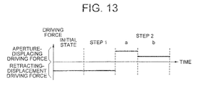
- FIG. 13 is a graph showing a driving force which acts on the diaphragm plate 20 a of the multiple-stage variable diaphragm according to the fourth embodiment, for displacing the diaphragm plate 20 a from the retracted position to the aperture position.
- a structure of the multiple-stage variable diaphragm according to the fourth embodiment being similar to the structure of the multiple-stage variable diaphragm 100 according to the first embodiment, the description in detail thereof is omitted.
- a case in which the diaphragm plate 20 a is displaced is described below, and a case of displacing the diaphragm plate 20 b or the diaphragm plate 20 c is the similar to the case described below.
- step 2 a In the method of driving the multiple-stage variable diaphragm according to the fourth embodiment, as shown in FIG. 13 , after a strong driving force is exerted once as the aperture-displacing driving force which is exerted to the diaphragm plate 20 a to be displaced from the retracted position to the aperture position (step 2 a ), a driving force weaker than the driving force in step 2 a is exerted (step 2 b ).
- the driving force of step 2 a is optimized by a force necessary for displacing the diaphragm plate 20 a from the retracted position to the aperture position, and an operating time is optimized by a time for displacement of the diaphragm plate 20 a from the aperture position to the retracted position.
- the driving force of step 2 b is optimized by the gravitational force, the impact from outside, and the acceleration etc. which is supposed to be acting on the diaphragm plate 20 a . In this manner, by reducing the aperture-displacing driving force according to the requirement, it is possible to reduce electric power consumption.
- FIG. 14 is a graph showing a driving force which acts on a diaphragm plate 20 a of the multiple-stage variable diaphragm according to the fifth embodiment, for displacing the diaphragm plate 20 a from the retracted position to the aperture position.
- a structure of the multiple-stage variable diaphragm according to the fifth embodiment being similar to the structure of the multiple-stage variable diaphragm 100 according to the first embodiment, the description in detail thereof is omitted.
- a driving force in the form of a sinusoidal wave is exerted as the aperture-displacing driving force which is exerted to the diaphragm plate 20 a to be displaced from the retracted position to the aperture position (step 2 a ).
- a driving force is exerted intermittently as the aperture-displacing driving force which maintains a state of the diaphragm plate 20 a after step 2 a (step 2 b ).
- a time-integration amount of the driving force at step 2 a is optimized by a force necessary for displacing the diaphragm plate 20 a from the aperture position to the retracted position
- the operating time at step 2 a is optimized by a time for displacement of the diaphragm plate 20 a from the aperture position to the retracted position.
- the aperture-displacing driving force to be exerted to the diaphragm plate 20 a is let to be in the form of a sine wave
- the aperture-displacing driving force may be let to be in the form of a triangular wave or in the saw tooth form, provided that the similar effect is achieved.
- the retracting-displacement driving force is exerted to all the diaphragm plates 20 a , 20 b , and 20 c at the time of putting ON a power supply of the apparatus, and the diaphragm plates 20 a , 20 b , and 20 c are displaced to the retracted position.
- the method of driving the light controlling apparatus according to the present invention is useful for a small-size image pickup equipment which includes a plurality of optical elements.
- a light controlling apparatus According to a light controlling apparatus, a control unit of light controlling apparatus, and a method of driving light controlling apparatus according to the present invention, there is shown an effect that it is possible to prevent an operation of the light controlling apparatus from becoming unstable due to an effect and interference of the plurality of optical elements.
Landscapes
- Physics & Mathematics (AREA)
- General Physics & Mathematics (AREA)
- Optics & Photonics (AREA)
- Diaphragms For Cameras (AREA)
Abstract
Description
Claims (22)
Applications Claiming Priority (3)
| Application Number | Priority Date | Filing Date | Title |
|---|---|---|---|
| JP2008-199377 | 2008-08-01 | ||
| JP2008199377A JP5307469B2 (en) | 2008-08-01 | 2008-08-01 | Light adjusting device driving method, light adjusting device control device, and light adjusting device |
| JPJP2008-199377 | 2008-08-01 |
Publications (2)
| Publication Number | Publication Date |
|---|---|
| US20100027094A1 US20100027094A1 (en) | 2010-02-04 |
| US8335030B2 true US8335030B2 (en) | 2012-12-18 |
Family
ID=41608059
Family Applications (1)
| Application Number | Title | Priority Date | Filing Date |
|---|---|---|---|
| US12/534,688 Active 2030-01-14 US8335030B2 (en) | 2008-08-01 | 2009-08-03 | Light controlling apparatus, control unit of light controlling apparatus, and method of driving light controlling apparatus |
Country Status (2)
| Country | Link |
|---|---|
| US (1) | US8335030B2 (en) |
| JP (1) | JP5307469B2 (en) |
Families Citing this family (5)
| Publication number | Priority date | Publication date | Assignee | Title |
|---|---|---|---|---|
| JP2013076900A (en) * | 2011-09-30 | 2013-04-25 | Olympus Corp | Light adjustment device |
| KR102635884B1 (en) * | 2018-10-31 | 2024-02-14 | 삼성전자주식회사 | A camera module including an aperture |
| JP7255189B2 (en) * | 2019-01-15 | 2023-04-11 | セイコーエプソン株式会社 | virtual image display |
| DE102020213648A1 (en) | 2020-10-29 | 2022-05-05 | Memetis Gmbh | Actuator and optics assembly with actuator |
| EP4314912A1 (en) * | 2021-03-30 | 2024-02-07 | BAE SYSTEMS plc | Projector |
Citations (4)
| Publication number | Priority date | Publication date | Assignee | Title |
|---|---|---|---|---|
| US3277772A (en) * | 1956-01-30 | 1966-10-11 | Perkin Elmer Corp | Optical scanning system |
| US5706128A (en) * | 1995-09-11 | 1998-01-06 | Edge Scientific Instrument Company Llc | Stereo microscope condenser |
| US6473217B2 (en) * | 2000-02-03 | 2002-10-29 | Seiko Precision Inc. | Diaphragm device |
| JP2006330314A (en) | 2005-05-26 | 2006-12-07 | Canon Electronics Inc | Light quantity adjusting device, imaging optical unit and imaging apparatus |
Family Cites Families (7)
| Publication number | Priority date | Publication date | Assignee | Title |
|---|---|---|---|---|
| JP3205714B2 (en) * | 1997-02-03 | 2001-09-04 | 日本電産コパル株式会社 | Imaging device |
| JP4131758B2 (en) * | 1998-05-21 | 2008-08-13 | 日本電産コパル株式会社 | Camera iris mechanism |
| JP2001215552A (en) * | 2000-01-31 | 2001-08-10 | Asahi Optical Co Ltd | Drive circuit for electromagnetic diaphragm |
| JP2002107792A (en) * | 2000-10-03 | 2002-04-10 | Canon Inc | Light control device |
| JP2003084183A (en) * | 2001-09-11 | 2003-03-19 | Canon Inc | Lens barrel and video camera equipped with the same |
| JP2006284733A (en) * | 2005-03-31 | 2006-10-19 | Matsushita Electric Ind Co Ltd | The camera module |
| JP4868899B2 (en) * | 2006-03-16 | 2012-02-01 | 株式会社リコー | Real-image observation optical system, imaging lens barrel unit, and imaging device |
-
2008
- 2008-08-01 JP JP2008199377A patent/JP5307469B2/en active Active
-
2009
- 2009-08-03 US US12/534,688 patent/US8335030B2/en active Active
Patent Citations (4)
| Publication number | Priority date | Publication date | Assignee | Title |
|---|---|---|---|---|
| US3277772A (en) * | 1956-01-30 | 1966-10-11 | Perkin Elmer Corp | Optical scanning system |
| US5706128A (en) * | 1995-09-11 | 1998-01-06 | Edge Scientific Instrument Company Llc | Stereo microscope condenser |
| US6473217B2 (en) * | 2000-02-03 | 2002-10-29 | Seiko Precision Inc. | Diaphragm device |
| JP2006330314A (en) | 2005-05-26 | 2006-12-07 | Canon Electronics Inc | Light quantity adjusting device, imaging optical unit and imaging apparatus |
Also Published As
| Publication number | Publication date |
|---|---|
| JP2010039030A (en) | 2010-02-18 |
| JP5307469B2 (en) | 2013-10-02 |
| US20100027094A1 (en) | 2010-02-04 |
Similar Documents
| Publication | Publication Date | Title |
|---|---|---|
| US11366333B2 (en) | Camera device having hand-shake correction function | |
| US11372260B2 (en) | Camera device having hand-shake correction function | |
| US11079565B2 (en) | Optical system | |
| CN104898347B (en) | Camera lens module | |
| EP3505985A1 (en) | Lens driving device, camera module, and camera-mounted device | |
| JP4923226B2 (en) | Lens driving device and coil winding method | |
| US8335030B2 (en) | Light controlling apparatus, control unit of light controlling apparatus, and method of driving light controlling apparatus | |
| JP2011039481A (en) | Lens drive device | |
| JP2012242801A (en) | Electromagnetically driven device | |
| JP2016020939A (en) | Lens driving device, camera module, and mobile terminal with camera | |
| JP5046304B2 (en) | Light control device | |
| TWM520206U (en) | Driving component and electronic device and electromagnetic driving module using the same | |
| JP5185088B2 (en) | Lens driving device and method of manufacturing lens driving device | |
| JP2024175108A (en) | Light quantity control device and mobile terminal | |
| JP2013186268A (en) | Lens driving device | |
| JP2013033186A (en) | Lens drive device, autofocus camera and portable terminal device | |
| KR20090080045A (en) | Blade Drives for Actuators and Cameras | |
| US20140169780A1 (en) | Light control apparatus | |
| JP2011013535A (en) | Light controlling apparatus and optical system | |
| JP2010204509A (en) | Lens drive device | |
| JP2010191331A (en) | Lens driving device | |
| JP2006350019A (en) | Lens drive device | |
| JP2015099274A (en) | Lens driving device | |
| JP2012008204A (en) | Lens driving device | |
| JP2011257705A (en) | Lens drive device |
Legal Events
| Date | Code | Title | Description |
|---|---|---|---|
| AS | Assignment |
Owner name: OLYMPUS CORPORATION,JAPAN Free format text: ASSIGNMENT OF ASSIGNORS INTEREST;ASSIGNOR:IDE, TAKAYUKI;REEL/FRAME:023046/0517 Effective date: 20090721 Owner name: OLYMPUS CORPORATION, JAPAN Free format text: ASSIGNMENT OF ASSIGNORS INTEREST;ASSIGNOR:IDE, TAKAYUKI;REEL/FRAME:023046/0517 Effective date: 20090721 |
|
| FEPP | Fee payment procedure |
Free format text: PAYOR NUMBER ASSIGNED (ORIGINAL EVENT CODE: ASPN); ENTITY STATUS OF PATENT OWNER: LARGE ENTITY |
|
| STCF | Information on status: patent grant |
Free format text: PATENTED CASE |
|
| FPAY | Fee payment |
Year of fee payment: 4 |
|
| AS | Assignment |
Owner name: OLYMPUS CORPORATION, JAPAN Free format text: CHANGE OF ADDRESS;ASSIGNOR:OLYMPUS CORPORATION;REEL/FRAME:039344/0502 Effective date: 20160401 |
|
| MAFP | Maintenance fee payment |
Free format text: PAYMENT OF MAINTENANCE FEE, 8TH YEAR, LARGE ENTITY (ORIGINAL EVENT CODE: M1552); ENTITY STATUS OF PATENT OWNER: LARGE ENTITY Year of fee payment: 8 |
|
| MAFP | Maintenance fee payment |
Free format text: PAYMENT OF MAINTENANCE FEE, 12TH YEAR, LARGE ENTITY (ORIGINAL EVENT CODE: M1553); ENTITY STATUS OF PATENT OWNER: LARGE ENTITY Year of fee payment: 12 |