US833482A - Self-condensing turbine. - Google Patents
Self-condensing turbine. Download PDFInfo
- Publication number
- US833482A US833482A US9682802A US1902096828A US833482A US 833482 A US833482 A US 833482A US 9682802 A US9682802 A US 9682802A US 1902096828 A US1902096828 A US 1902096828A US 833482 A US833482 A US 833482A
- Authority
- US
- United States
- Prior art keywords
- runner
- steam
- pump
- water
- turbine
- Prior art date
- Legal status (The legal status is an assumption and is not a legal conclusion. Google has not performed a legal analysis and makes no representation as to the accuracy of the status listed.)
- Expired - Lifetime
Links
- XLYOFNOQVPJJNP-UHFFFAOYSA-N water Substances O XLYOFNOQVPJJNP-UHFFFAOYSA-N 0.000 description 35
- 239000007788 liquid Substances 0.000 description 15
- 230000004048 modification Effects 0.000 description 11
- 238000012986 modification Methods 0.000 description 11
- 238000010276 construction Methods 0.000 description 8
- RLQJEEJISHYWON-UHFFFAOYSA-N flonicamid Chemical compound FC(F)(F)C1=CC=NC=C1C(=O)NCC#N RLQJEEJISHYWON-UHFFFAOYSA-N 0.000 description 8
- 230000005494 condensation Effects 0.000 description 6
- 238000009833 condensation Methods 0.000 description 6
- 239000012530 fluid Substances 0.000 description 5
- 230000001105 regulatory effect Effects 0.000 description 4
- 235000013405 beer Nutrition 0.000 description 3
- 150000001875 compounds Chemical class 0.000 description 3
- LTMHDMANZUZIPE-PUGKRICDSA-N digoxin Chemical compound C1[C@H](O)[C@H](O)[C@@H](C)O[C@H]1O[C@@H]1[C@@H](C)O[C@@H](O[C@@H]2[C@H](O[C@@H](O[C@@H]3C[C@@H]4[C@]([C@@H]5[C@H]([C@]6(CC[C@@H]([C@@]6(C)[C@H](O)C5)C=5COC(=O)C=5)O)CC4)(C)CC3)C[C@@H]2O)C)C[C@@H]1O LTMHDMANZUZIPE-PUGKRICDSA-N 0.000 description 3
- 102100034742 Rotatin Human genes 0.000 description 2
- 101710200213 Rotatin Proteins 0.000 description 2
- NAXKFVIRJICPAO-LHNWDKRHSA-N [(1R,3S,4R,6R,7R,9S,10S,12R,13S,15S,16R,18S,19S,21S,22S,24S,25S,27S,28R,30R,31R,33S,34S,36R,37R,39R,40S,42R,44R,46S,48S,50R,52S,54S,56S)-46,48,50,52,54,56-hexakis(hydroxymethyl)-2,8,14,20,26,32,38,43,45,47,49,51,53,55-tetradecaoxa-5,11,17,23,29,35,41-heptathiapentadecacyclo[37.3.2.23,7.29,13.215,19.221,25.227,31.233,37.04,6.010,12.016,18.022,24.028,30.034,36.040,42]hexapentacontan-44-yl]methanol Chemical compound OC[C@H]1O[C@H]2O[C@H]3[C@H](CO)O[C@H](O[C@H]4[C@H](CO)O[C@H](O[C@@H]5[C@@H](CO)O[C@H](O[C@H]6[C@H](CO)O[C@H](O[C@H]7[C@H](CO)O[C@@H](O[C@H]8[C@H](CO)O[C@@H](O[C@@H]1[C@@H]1S[C@@H]21)[C@@H]1S[C@H]81)[C@H]1S[C@@H]71)[C@H]1S[C@H]61)[C@H]1S[C@@H]51)[C@H]1S[C@@H]41)[C@H]1S[C@H]31 NAXKFVIRJICPAO-LHNWDKRHSA-N 0.000 description 2
- 230000001419 dependent effect Effects 0.000 description 2
- 230000003467 diminishing effect Effects 0.000 description 2
- 239000000463 material Substances 0.000 description 2
- 239000002184 metal Substances 0.000 description 2
- 230000037452 priming Effects 0.000 description 2
- PCLIRWBVOVZTOK-UHFFFAOYSA-M 2-(1-methylpyrrolidin-1-ium-1-yl)ethyl 2-hydroxy-2,2-diphenylacetate;iodide Chemical compound [I-].C=1C=CC=CC=1C(O)(C=1C=CC=CC=1)C(=O)OCC[N+]1(C)CCCC1 PCLIRWBVOVZTOK-UHFFFAOYSA-M 0.000 description 1
- 241001527902 Aratus Species 0.000 description 1
- 229910000760 Hardened steel Inorganic materials 0.000 description 1
- 235000008694 Humulus lupulus Nutrition 0.000 description 1
- 244000025221 Humulus lupulus Species 0.000 description 1
- 235000010627 Phaseolus vulgaris Nutrition 0.000 description 1
- 244000046052 Phaseolus vulgaris Species 0.000 description 1
- MWPLVEDNUUSJAV-UHFFFAOYSA-N anthracene Chemical compound C1=CC=CC2=CC3=CC=CC=C3C=C21 MWPLVEDNUUSJAV-UHFFFAOYSA-N 0.000 description 1
- 230000000052 comparative effect Effects 0.000 description 1
- 239000004020 conductor Substances 0.000 description 1
- 230000001276 controlling effect Effects 0.000 description 1
- 230000007547 defect Effects 0.000 description 1
- 230000003292 diminished effect Effects 0.000 description 1
- 238000007599 discharging Methods 0.000 description 1
- 239000000446 fuel Substances 0.000 description 1
- 239000011521 glass Substances 0.000 description 1
- 230000005484 gravity Effects 0.000 description 1
- 230000004941 influx Effects 0.000 description 1
- 238000000034 method Methods 0.000 description 1
- 238000005086 pumping Methods 0.000 description 1
- 238000009877 rendering Methods 0.000 description 1
- 230000035939 shock Effects 0.000 description 1
Images


Classifications
-
- F—MECHANICAL ENGINEERING; LIGHTING; HEATING; WEAPONS; BLASTING
- F03—MACHINES OR ENGINES FOR LIQUIDS; WIND, SPRING, OR WEIGHT MOTORS; PRODUCING MECHANICAL POWER OR A REACTIVE PROPULSIVE THRUST, NOT OTHERWISE PROVIDED FOR
- F03B—MACHINES OR ENGINES FOR LIQUIDS
- F03B3/00—Machines or engines of reaction type; Parts or details peculiar thereto
-
- F—MECHANICAL ENGINEERING; LIGHTING; HEATING; WEAPONS; BLASTING
- F04—POSITIVE - DISPLACEMENT MACHINES FOR LIQUIDS; PUMPS FOR LIQUIDS OR ELASTIC FLUIDS
- F04D—NON-POSITIVE-DISPLACEMENT PUMPS
- F04D17/00—Radial-flow pumps, e.g. centrifugal pumps; Helico-centrifugal pumps
- F04D17/08—Centrifugal pumps
- F04D17/16—Centrifugal pumps for displacing without appreciable compression
- F04D17/162—Double suction pumps
-
- Y—GENERAL TAGGING OF NEW TECHNOLOGICAL DEVELOPMENTS; GENERAL TAGGING OF CROSS-SECTIONAL TECHNOLOGIES SPANNING OVER SEVERAL SECTIONS OF THE IPC; TECHNICAL SUBJECTS COVERED BY FORMER USPC CROSS-REFERENCE ART COLLECTIONS [XRACs] AND DIGESTS
- Y02—TECHNOLOGIES OR APPLICATIONS FOR MITIGATION OR ADAPTATION AGAINST CLIMATE CHANGE
- Y02E—REDUCTION OF GREENHOUSE GAS [GHG] EMISSIONS, RELATED TO ENERGY GENERATION, TRANSMISSION OR DISTRIBUTION
- Y02E10/00—Energy generation through renewable energy sources
- Y02E10/20—Hydro energy
Definitions
- My invention relates to improvements in steam-turbines and the objects of myinvention are to produce a device ofthis character Y which may be driven at the very highest possible speeds dependent only on the tensile strength of the material, to practically do away with friction,to have'the runningparts accurately and automaticallybalanced,and to have them so arranged that when in rotation they will be supported on practically nothing but fluid.
- a further object is to have the apparatus self-condensing and free from torsional strains, the power which the apparatus pro- .duces being utilized as hereinafter described.
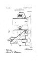
- Figure 1- represents a cross-section of a steam-turbine and a centrifugal pump combined.
- Fig. 2 is a side view ofthe same, glartly in section, the section being taken on t 1 fla modification, the rotating part of runner Fig. Sisagzross-se'dtiona I 'tatingpart'shown i'n-Fig'. 4.
- Fig. 6 isa'n end view of-the rotating part or runnerof the closed type, such asis. shown in Fig; 3.
- Fig. 8 is a cross-section of a modification, showing separate condensing means.
- Fig. 9 is a broken cross-section of a modifica- 5 0 tion, showing. 'a self-condensingsteam-tur binle, a puni a liquid-motor, and an electric generator, a l .inone structure; and
- Fig. 10 is a'detail view, partly vin-section, of one of the.' Fig.-'11 is a. cross-section of an- -.bearings. u other modification; andFig. 12 1s a bottom Specification of Letters Patent Applination filed March 5, 1902. Serial No. 96,828.
- Fig. 13 is a cross-section of another modification, showing a steam-' turbine and combined centripetal and contrifugal pump; and Fig. 14 is a detail view showing the means for supporting and ad-" justing the pressure-ring.
- a represents a shaft on which the rotating runner-is sup orted while atrest. so that there is very little friction between the shaft and the casing, or said shaft may be supported on water-bearin s, as shown in my even date, en-
- the casin own is the casing of one type of centrifuga pumps supported on a standard 70 and provided with. inlet-pipes l and 1a,.
- T is rotating part or runner 'scharges into a discharge-chamber n made in the form of a volute and showrfas largest at the bottom, where the discharge takes place, although I do not restrict myself to "this arrangement, either of suction or 'discharge, as the inlet-pipesmightcome in from .the side or the top and the dischargeeorifice may be placedin any desired osition.
- .rotatin part or runner secure to the shaft 0, 5 .in any. esired manner is composedoftwo op-' positely-coned portions '0 and p, which are united by two oppositely-coned portions g and 1', arranged at'right angles to the first coned, portions-and constituting a guidi'ng-vane.
- I can use as many rings of im- -.peller-blades (providedthe same number is used on the same sideof the central vane). and as many rings of reacting or diverting blades'as I desire, which latter series of rings will be fixed to the casing,'such arrangements being well known in steam tu'rbines. In this way I am enabled to obtain energy from I p the steam byimpact, reaction, expansion, 'or
- passages 3 4 Between the wings s and t and the casing are passages 3 4,
- 5 and '6 represent circular annular guide-plates secured to the casing and over la ping the inner peripheries of the ringss andv t, 'ut notifin contact t erewith,it being one of the essential features of my invention that'- the rotating part or runner shall be compelled to rotate entirely free from the casing, thereby diminishing friction .and ermitting no slip of the liquid column.
- the purpose of these guide-plates 5 and 6 is to direct the water coming in from the pipes l and m into the spaces between the rings .9 and t and the central vane.
- the side wings s and t are cut away, asshown at 7.
- This cut-away portion is in the form of a spiral, commeneingat the outer edge of one-of the arms8 and gradually depending until just behind the next succeeding arm, being a proximately in the form of a reversed spira the. deepest part being behind the runner-arm. at the point of vacuum, since the pressure-generated y each one of the arms is greatest at the point 9, and behind the arm 8 there is'a vacuum when the apparatus rotates in a liquid
- the centrifugal pump shown is of the closed runner typeethat is-to say, it has wings s and t,between which the central vane the Water passes.
- I may use, however, a rotatin 'partof the-open runner t e, as shown in igs', 4 and5, in which .the si e plates are eliminated and the rings of impeller-blades are attached directly to the m V
- the water grom being thrown out and condensing the "s'team'before it passesthrough the impeller blades the rings let into the casingwhich inclose the divertersblades .may'he made to overlap the rings. carrying the impellercally does awa withfriction of both air, li
- Fig. 7 isshown a side elevation of m combined steam-turbine and pump, which drives aPelton wheel or other water-motor,
- Fig. 7, 47 re resents a steam-turbine-of the construction a eady described andshown, for exam le, in Fig. 1.
- 48 represents a Pelton wheel or other desired form of water-- "motor.
- the steam turbine and wheel are connected by a pipe or waterway 49, which. 5 connects with the discharge-chamber of the steam turbine and delivers the impelli fluid to the motor 48.
- 'To the shaft 50 of the water-motor is coupled the shaft of a dynamo 5i. e If desired, however, this shaft 50 could be used to run any form of machinery in any of the usual ways.
- the means for goverm' the rate ofqspeed for the steam-turbine now be described.
- Fi 7 52 represents j s ber 53, from-w 'ch branch pipes 54' and 55 conduct the steam to the steam turbine'.
- a pipe 56 is connected with the dischargechamber of the centrifugal pump and at its other end is connected'wrth the casing 57, in which is a dia hrag'm or piston. This is conj nected to awailve in thecha-mber 53 andis-so arranged thatthe varying pressure in the pipes 5,4and 55 as esired.
- the variations me be adjusted as desired by a'hand screw an spring, asjcommonin pressure-regulators.
- Th1s is regulated in the usual-way b' meansof the va yes'58-a nd. 59, which eontro the fluideje'ts-jwhi hdrivethe' .-water-motor,-.which is preferably-,madewith/ double sets of buckets in the usual ways 1
- the speed'of the water-wheel can be regulated 3e roo i its.
- any usual form of governor such as a centrifugal governor. 1f the speed is increased above a certain limit, the amount of water passing through the jets is automatic- ]Ially diminished by this governor. This refsults in a greater pressure in the pipe or waterway 49, which in turn increases the presestablishes apositive and extremely closespeed regulation, dependent simply upon the speed to which the water-motor 48 is set.
- the steam is condensed and'carried with the is forced the the discharge-champump, 'awater niotor, andan elector.
- trio generator all one. unitary structure,- Fig. 10 showing details thereof.
- 80' represents a centrifugal pum of the closed-runner type, similar to that s own in Fig. 1, provided with curved impeller-arms, side wings, and rings of impeller blades mounted thereon.
- the casing of all these structures may be divided into either vertical or horizontal sections.
- 81 represents the upper part of the stationary casin which is cored out, leaving plates 82 83, wit a passage 84 therebetween.
- the part 86 is] cored out,- leaving passages 87, 88, and 89, the'passage 88 bein the water-inlet and the assages 84,87, am? 89 being the water-outets.
- the part 86 rests upon the stationary which base is also cored out to form passages, which are continuations of thepassages 87, 88, and 89.
- - Steam is admitted through a pipe 92 (shown in dotted lines) and through a passage cut in the casing 81- into an annular space 93, cut out in the casing 81, from whence it passes from between the diverterblades 94- and against the impeller-blades 95,
- a metal ring 97 Secured; aldjustably to the base 90, by means of bolts 96, is a metal ring 97, which supports the field-coils of an electric genera- In this'case' a generator of direct current isi1sed;. but I may of course use a gen- :erator of; alternating currents, if desired.
- Secured by. bolts l0l to' the ring-97 are one ormore bracket arms102, in which is-sup orted a sliding brush-supporting ring 103, w 'ch may befasten'ed in said brackets in any desired .position by screws 104..
- Brushes 105 are car- .ried in brush-holders 106, supported by the ring 103, and may be adjusted in a circle around the c mmutator as desired.
- the shell orcasin'g 108 is supported on ant1fi'1ct1onrollers 110, preferably mounted in'spacing-rings in the usual man- I ner .to form a ca e; These anfiiriction-rollers are sup'porte on a ring 111 preferably made of hardened steel annular in its general form, but thickest at the bottom, as'shown in Fig. 10, this rmg 11 1 being mounted on the stationary casing 81 86.
- this ring 114 On the inside of this ring 114 are mounted buckets arranged in a double series, so as to split up the current of water thrown against the same after its energy has been utilized and to divert it on elther sideinto the discharge-passages.
- buckets 116 are concavedand also curved reversely to each other, as shown in Fig. 9, coming to a line 117 in the center, which line is outside ofthe central vane of therunner and in the same plane.
- the admission of the water to the water-wheel may be controlled in any desired'way for exam-.
- The. pump-runner may be of multiplex.
- the meansfor driving the runner by means of steam may also be simple, compound, or
- the casing 1.08 a pulle inste'adof having it can-y thearmature-coi s. Power can also be taken from a' shaft torsionally by 'a slight.
- bins-wheel and pump-runner combined which I desire to run at very high speeds. It is not feasible or desirable that the casing carrying the armature-coils should be run at the same high speed, and by-a proper proportionin of the parts this will not be the case. It wil be understood that the speed of the turbinewheel and pump-runner may be anywhere from ten to one hundred times as fast as the s eed at which the armature is driven, thus i ustrating one of the important points of this invention, the flexibility of the transmitting medium rendering it possible to use very small amounts of water moved at a very high speed and pressure to obtain large amounts .of power. As already described in connection with Fig. 7, the speed to which the armature is set in the be inning may be used to govern the speed of the whole apparatus.
- FIGs. 11 and 12 I have shown still another modification of my ap aratus in which a vertical pump is-usedt at is to say, a pump .whose runner runs in a horizontal lane and whose axle ,if one were used, would be in a vertical plane.
- This modification like all vertical-centrifu al pumps, may, if desired, be submerged w en in use, thereby obviating the necessity of priming the pump.
- 118 represents the casing, which may be made either in the form of a' shell or in sections, if desired
- a steamway 119 is cored out connecting with a steam-pipe at any desired point.
- This delivers into a circular passage 120, which passage is connected by ports 121 with
- the regulation of the speed may be accomplished by variations-in t e pressure affecting the amount of steam conducted, as already described in connection with Fig. 7.
- the diverterblades 122 After passing through the parts 121 the steam impinges upon the diverterblades 122, which are curved in opposite di rections.
- These blades may be made in one piece or separate, as desired, and by means of said blades the steam is dividedinto two columns or continuous jets,which jets pass between the impeller-blades 123 and 124, se-
- the arms in the passage 126 serving to draw the liquid toward the center centripetally and the'arms in the passage 127 serving to throw the same out from the center centrifugally.
- the top of the pump runner is' curved upward, as shown at 129,
- a waterway 138 (or a separate pipe may be used, if desired,) which waterway or pipe is connected with the discharge'chamber or passage 130, the
- TlllS' arrangement furnishes a convenient and effective water bearin forthe combined puin -runner and tur inewheel, whereby sai combined structure is sup orted on fluid during its rotation, any
- Fig. 9 I have shown a water-motor directly coupled to the shaft of a dynamo. It is obvious that this shaft could be used in various other relations to transmit power. In some instances it is desirable to reverse the motion of the shaft, as in marine work. This reversal may be quickly and easilyefi'ected in thefollowing manner:
- the water-motor may be provided with two sets of buckets curved opposite directions and" with separate "sets of corresponding jet-nozzles.
- This valve located in the main watersupply pipe leading from the pump to the depends, as stated efore, on the pressure in the discharge-chamber of the pump. Moreover, by moving this valve so that itwill direct jets of varying and unequal power upon the oppositely-arranged sets of buckets the speed and direction of rotation of the motorshaft may be exactly and almost instanta neously regulated.
- This valve may of course be operated either pneumatically, hydraulically, elect1ically, or by any desired mechanical devices from a distant point.
- valve in the engine-room of a ship may be directly operated from the pilothouse thereof. This is an im 'ortant feature, inasmuch as the reversal. o the operatingshaft'does not necessitate the slowing down, stopping, and starting again of .the prime mover, as is the case with all motive devices known to me. Moreover, the prime mover is maintained atall times in its highest state of efficiency and readiness'to transmit its-en- 'ergyin my invention.-,
- My invention is especially designed to re; quiztoa the weight, space, cost, and vibration of the device and atthe same iii:
- Fig. 13 is shown a cross-section of a combined centrifugal and centripetal pump and steam-turbine.
- 139 represents the casing provided with a water-inlet 140, which is divided into two branches 141 and 14.2, which deliver to opposite sides of the pump-runner.
- 143 represents the discharge passage or chamber, preferably in the form of a volute largest at the bottom. I have shown the water-inlet pipes as coming from below and the discharge-passage at the bottom. It is obvious, however, that these passages may be located in any desired po-
- the upper part of the volute is provided with a passage into which is fitted a steam-ejector pipe used for priming the pump in the usual way, as has already been described in' connection with the other modifications.
- the pump-runner itself is provided with a central vane 144, made in the form of a This is-mounted upon a central part 145, which part is provided with extensions 146 and 147, in which the supporting-shafts are mounted These extensions are cut away, as shown at 148 and 149, for the reception of the hollow shafts, which are confined therein by nuts 150 and 151.
- the supporting shafts 152 and 153 are 7 hollow and provided with enlargements 1 54 and 155 at their inner ends.
- the passages 156 and 157 iii-said shafts are turned upward and inward at their inner ends, as shown at 158 and 159, for the purpose of discharging streams of-water upwardly and inwardly against the pump-runner to sustain the weight and overcome any lateral thrust thereof.
- These shafts pass through bearings 160 and 161, located in extensions in the casing, and into boxes 162 and 163, which are provided with removable heads 164 and 165,
- Lock-nuts 168 and 169 engage-these shafts, and bolts 170 and 171 secure these lock-nuts in position.
- the outer ends-of the shafts are squared, as shownat 172and 17 3, for the purpose of receiving the head of a wrench,-
- shafts may be. adujsted in orner.
- 174 and-175 represent pipesconnected wit-h 176 and '177 are valves volumeof the watertherein.
- 178 and 179 represent inlet-pipes for the steam, which passes between diverter blades .180 and .181 and thence intothe im eller-blades 182 and 183, whichare' mounte onthe pump-rimner.
- pump-runner itself is provided with wings 184 and 185, approximately parallel to the central vane 143. Between these wings and the central vane are curved impeller-vanes 186 and 187, so arranged as to drive the liquid out into the discharge-passage 143.
- Another set of curved arms 188 and 189 are mounted on the outer sides of the runner. These arms are curved in the opposite direction from the arms 186 and 187 and serve to draw in the liquid centrip'etally and deliver it into the pump-runner near the center, from whence it is discharged centrifugally. These arms of course do not extend up to the central portion of the runner, as'it is necessary to leave a passage there for the influx of the water.
- the runner itself is cut away from the center, as shown at 190 and 191, to aflord a free passage for the water or other liquid
- this construction I am enabled to run the apparatus at a very highspeed without using a separate pump to feed the centrifugal part of the runner, as is com mon'ln apparatus of this type, the vacuum being established and maintained at all times.
- passages 192 and 193 which connect 7 with the discharge-passage 143-loy narrower 'passages'194 and 195, the result being that the liquid thrown out by the-centrifugalaction of the pump-runner draws with it the steam after it has passed through the impeller-blades into the.
- This 196 may, however, be separated from, sai central vane, although located proximity thereto, and in Fig. 14 I have shown means for supporting and adjusting its 199 represents a rod passing through. the casing and provided with a hand-wheel 200. This rod is secured inposition by lock-nuts 201. I As many of these rods as desired may be used; but I prefer to use at least three, preferably spaced at equal distances apart, two below the center of the casing and one above it. .It may also, if desired, be supported eccentrically hpon lugs arranged in the volute, passage 143.
- This ring 196 may be adjusted so that it will be” eccentric to the central vane 144, preferably nearest to said vane at the bottom, the result being thatthe pressure of the discharged liquid being greatest at the bottom reacts against the runner, thereby overcoming its wei ht and the thrust due to its rotation.
- the runner can e determined whetherthe runner is runnm in its proper position by the means descri ed m connection .with the runner shown in Fig. 5 or in any other convenient way for example, by. having ports fitted, with glass covers cut in the casing at suitable points.
- a movable part or runner composed of a central portion, curved arms, wings substantially arallel thereto anid rings of vanes attached t ereto on either s1 e. v
- a rotating part or I runner consisting of a double-coned central portion, a double-coned vane secured thereto, curved arms, wings'substantially parallel to said arms, and rings of vanes or blades secured on the outer side of each of said wings.
Landscapes
- Engineering & Computer Science (AREA)
- Mechanical Engineering (AREA)
- General Engineering & Computer Science (AREA)
- Chemical & Material Sciences (AREA)
- Combustion & Propulsion (AREA)
- Structures Of Non-Positive Displacement Pumps (AREA)
Description
No. 833,482. 7 I PATENTED OCT. 16, 1906. R. S. PRINDLE. v
SELF QONDBNSING TURBINE.
APPLICATION FILED 11112.5, 1902.
8 SHEETS-SHEET 1.
Witnesses No. 833,482. PA'iBNTED 0GT.16, 190's.
R. s. PRTNDLE. I SELF counrmsme TURBINE.
APPLIUATIOK FILED HAB- 5, 1902.
I 8 SHEETS-SHEET 2.
luinntoz No. 833,482. 'PATENTED OCT. 16, 1906.
R. s. PRINDLB.
SELF GONDENSING TURBINE. APPLIOATION FILED 11mm, 1902.
8 SHEETS-SHEET 3.
PATENTED 00116, 1906,
R. s. PRINDLE. SELF GONDENSING TURBINE. APPLIOQTION'FILED HA3. 5, 1902.
witnaaau No. 833,482. PATENTED 0M. 16, 1906-.
- R. s. PRINDLE.
SELF GONDENSING TURBINE.
APPLICATION FILED nun. 5, 1902.
B SHEETS-BEBE! 5.
III?
gamut No. 833,482; v PATENTED OCT. 16, 190
R. s.- PBINDLE.
85m" GONDBNSING TURBINE.
APPLICATION rmm MAB. 5, 1902.
a sums-sum e.
Zjnoemtoz Wihwaoea PATENTED 0GT.16,1906.'
' R. s. PRINDLB.
. SELF GONDBNSING TURBINE.
APPLICATION FILED MIR. 5, 1902.
a SHEETS-SHEET 7.
"mun;
l y Y I 0 z: 14
PATEN'IED OCT. 16, 1906.
R. S.- PRINDLE. SELF GONDENSING TURBINE.
APPLICATION FILED MAR. 5, 1902.
8 SHEETS-SHEET 8- Y I i 1 X /W YAE 1 im Tsliowrr therein-being of "the o 11 type. viewoft e runner or ro- .UNITED STATES PATENT OFFICE;
ROSCOE S. PRINDLELQF NEW YORK, N. YQASSIGNOR OF ONE*HALF TO. CHARLES H. TOMPKINS AND VINCENT G. TOMI KINS, NEW 3 YQRK,' N. Y.
To all whom it may'concern:
Be it known that I, RosooE S.PRINDLE, a
. citizen of the United States, residing at New York,in the county of-New York and State 5 of New York,.have invented certain new and useful Improvements in Self-Condensing Turbines; and I do hereby declare the following to bea full, clear, andexactdescription of the invention, such as will enable others skilled in the art to which it appertains to make and use the same.
My invention relates to improvements in steam-turbines and the objects of myinvention are to produce a device ofthis character Y which may be driven at the very highest possible speeds dependent only on the tensile strength of the material, to practically do away with friction,to have'the runningparts accurately and automaticallybalanced,and to have them so arranged that when in rotation they will be supported on practically nothing but fluid. p
A further object is to have the apparatus self-condensing and free from torsional strains, the power which the apparatus pro- .duces being utilized as hereinafter described.
With these objects in view my invention consists in the constructions and combina-' tions of parts, as hereinafter described, and
particularly pointed out in the claims.
In the accompanying drawings, Figure 1- represents a cross-section of a steam-turbine and a centrifugal pump combined. Fig. 2 is a side view ofthe same, glartly in section, the section being taken on t 1 fla modification, the rotating part of runner Fig. Sisagzross-se'dtiona I 'tatingpart'shown i'n-Fig'. 4. Fig. 6 isa'n end view of-the rotating part or runnerof the closed type, such asis. shown in Fig; 3. Fig.
2.5. 7 isan elevation showing the means whereby power is taken from thesteam-turbine and utilized. Fig. 8 is a cross-section of a modification, showing separate condensing means. Fig. 9 is a broken cross-section of a modifica- 5 0 tion, showing. 'a self-condensingsteam-tur binle, a puni a liquid-motor, and an electric generator, a l .inone structure; and Fig. 10 is a'detail view, partly vin-section, of one of the.' Fig.-'11 is a. cross-section of an- -.bearings. u other modification; andFig. 12 1s a bottom Specification of Letters Patent Applination filed March 5, 1902. Serial No. 96,828.
companion application 0 titled Method of transmitting power. .This shaft'is mounted in boxes I) c, su. portedee difl'erent planes. r Fig. 3Vis aside view, partly in section, of the rotating part or runner, the section bein I taken in two planes. 4 isa side view 0 Substantially v and on either si e thereof are two s .s and t,
SELF-CONDENSINVG TURBINE. w
plan view, partly in section,. of the-runner shown in Fig. 11. Fig. 13 is a cross-section of another modification, showing a steam-' turbine and combined centripetal and contrifugal pump; and Fig. 14 is a detail view showing the means for supporting and ad-" justing the pressure-ring.
Referring to Fig. 1, a represents a shaft on which the rotating runner-is sup orted while atrest. so that there is very little friction between the shaft and the casing, or said shaft may be supported on water-bearin s, as shown in my even date, en-
in extensions upon the casing, sai boxeshaving removable heads d e, which are fastened thereto by bolts f. In each end of the shaft a set-screw g is inserted, and a washer 7 5 or spacing-block his held between the head of said screwand the end of the shaft. Another set-screw '5 passes throu h the head e and contacts with the-head o the screw By this arrangement the shaft may be a "justed or may be allowed a slight lateral play.
The casin own is the casing of one type of centrifuga pumps supported on a standard 70 and provided with. inlet-pipes l and 1a,.
which deliver to o 1plosite sides of the rotating art or runner. T is rotating part or runner 'scharges into a discharge-chamber n made in the form of a volute and showrfas largest at the bottom, where the discharge takes place, although I do not restrict myself to "this arrangement, either of suction or 'discharge, as the inlet-pipesmightcome in from .the side or the top and the dischargeeorifice may be placedin any desired osition. The
.rotatin part or runner secure to the shaft 0, 5 .in any. esired manner is composedoftwo op-' positely-coned portions '0 and p, which are united by two oppositely-coned portions g and 1', arranged at'right angles to the first coned, portions-and constituting a guidi'ng-vane.
arallel to this guidingevane and thewater dischar ed by therqtation ofthe runner passes throu the passages between the wings s and t an the vanes q and r; these. win sbeing of coursecut away at the center to a low the liquid tofreel'y enter the central and inclosed part of the runner. From points nearthe centralpart of the runner curved spiral webs a run to, the periphery of. no
In motion it is practica 1y balanced 65 i the runner., The parts of these webs which pass between the wings s and the central vane are enlarged and extended to form arms completely connecting the vane and 'side wings. I do not restrict myself, however, to the number of webs and arms shown, nor to having them made exactly inthe form of a true spiral, the number, pitch, and throw of the webs and arms depending upon the volumes, speeds, and powers of the combined turbine and pump. On each of the wings s and t and symmetrically arranged in regard to. the central vane are rings of im eller blades or vanes '12. In Fig. 1 I have s own these rings arranged about midway of the wings s and t; but it is obvious that they may be arranged either nearer the inner periphery or nearer the outer periphery thereof, as
' may be desired. These blades and vanes are number or position thereof. Steam may be i the casin if desired.
steam v to' the 'and, moreover, that different pressures of steam may be ap conveyedby an annular assage cored out of fact, any of the usual an well-known means for supplying impeller-blades maybe used,
so arrange the apparatus .plie'd todifi'erent parts of the rings of the impeller-blades, the pressures on ,either side of the runner being, however, balancedfi In this way-I am enabled to ractically support the'weight of the runner y the pressure of the steam used to drive it and also to cause the runner-to be automatically and perfectly balanced in the center of the casing. In this figure I have shown-on either side of the central vane a single rowof impeller blades and a single 'row' of diverting-vanes. It is obvious that I am notjrestricted to-such an ar-- 'rangement. I can use as many rings of im- -.peller-blades (providedthe same number is used on the same sideof the central vane). and as many rings of reacting or diverting blades'as I desire, which latter series of rings will be fixed to the casing,'such arrangements being well known in steam tu'rbines. In this way I am enabled to obtain energy from I p the steam byimpact, reaction, expansion, 'or
any combination thereof; Between the wings s and t and the casing are passages 3 4,
into which'the steam emerges afterpassing through the impeller-blades. Thesepassages 3,and 4 are contracted at their outer.
1 ends, the result being that when the rotating part is driven the water or other fluid passitggl out between the wings s and t andthe centr vane into the discharge-chamber n. draws along with it the steam through these narrow assages out of the passages 3 and 4 and con enses'it, also at the same time .drawing out any air that there may be in the casing or entrained in the steam. In this way the steam is jetted against a moving column of water, and condensation is practically in-- stantaneous. Moreover, there is a steady current of water passing'through the discharge-chamber in a circular direction, and
the exposure of the exhaust-steam to this moving column of water causes instant condensation, as in a jet;condenser, the result being that the water driven by the runner carries with it. the condensed steam and any air that may be present and discharges them all through the exhaust-opening. This, in
efiect, allows the rotating partor runner to run in a vacuum, renderingit possible to run the a paratus at'high speeds with a comparative y small quantity of steam This 1111,
stantaneous condensation greatly reduces the power necessary to operate the apparatus. 5 and '6 represent circular annular guide-plates secured to the casing and over la ping the inner peripheries of the ringss andv t, 'ut notifin contact t erewith,it being one of the essential features of my invention that'- the rotating part or runner shall be compelled to rotate entirely free from the casing, thereby diminishing friction .and ermitting no slip of the liquid column. The purpose of these guide-plates 5 and 6 is to direct the water coming in from the pipes l and m into the spaces between the rings .9 and t and the central vane.
As shown in Fig. 2, the side wings s and t are cut away, asshown at 7. This cut-away portion is in the form of a spiral, commeneingat the outer edge of one-of the arms8 and gradually depending until just behind the next succeeding arm, being a proximately in the form of a reversed spira the. deepest part being behind the runner-arm. at the point of vacuum, since the pressure-generated y each one of the arms is greatest at the point 9, and behind the arm 8 there is'a vacuum when the apparatus rotates in a liquid InFigs. 1, 2, and 3 the centrifugal pump shown is of the closed runner typeethat is-to say, it has wings s and t,between which the central vane the Water passes. I may use, however, a rotatin 'partof the-open runner t e, as shown in igs', 4 and5, in which .the si e plates are eliminated and the rings of impeller-blades are attached directly to the m V For the purpose of-preventihg the water grom being thrown out and condensing the "s'team'before it passesthrough the impeller blades the rings let into the casingwhich inclose the divertersblades .may'he made to overlap the rings. carrying the impellercally does awa withfriction of both air, li
blades, this arrangement being shown in Fig.
5, and the inclosing rings being numbered 10. Moreover, I prefer to make the impellerblades mounted upon the runner concaved,
so that the steam coming in strikes the bottom thereof and is thrown out at an an 1e .thereto, which angle, is directed toward t 1e not permitting the water to enter theimpact- 6 andverygreat advanta es.
space.
In Fig. 7 isshown a side elevation of m combined steam-turbine and pump, which drives aPelton wheel or other water-motor,
which motor in turn supplies power for any desired purpose-such, for instance, as the' shaft fora dynamo, to which in Fi 7 the shaft of. the water-motor is coup ed. In practice it wouldonotdo to couple a dynamoshaft directly to the axle of a turbine for several reasons. In the first place, very high speeds are necessary, to obtain the highest efflciency from a steam-turbine. Fifty thousand revolutions a minute is notan excessive number. i This is far in excess of any rate of speed at whichthe shafts of dynamos have up to the present time been driven. Commercial dynamos are never driven more than five thousand revolutions a minute, and the average is considerablyless than this. It is evident therefore that it is impracticable 'my'steam-turbine rrmner. Another reason is that I desire to make .the steam-turbine small in size and cheap inconstruction,which could not'be done if it were coupled directly to. the shaft of a dynamo, for which purpose, among others m improved apparatus has been designed. been driven commonly at much higher speed than other kinds of machine latter case the objection would Another reason is that if the dynamo were coupled directly to the shaft of therunner a torsional strain would be set up in said shaft,
which is oneofthe things Idesire-to avoid, since this strain wouldresultjn a tendency to destroy the balance of .thetu'rbine, deflecting the. Shaf and bindingfthe gears, and makingvery carefully arranged and elaborate bean ings necess Moreove r, iffsuch a torsional strain existe it would be exceedingly drflicult, if not impossible, to cause the combined turbine and runner to float upon the li 'uid-a t which is oneof theespecial ob ects'ofmy mvention and which results in special Inm construction the very lightr'es't- 'dof tur inej; compared with the amount of power obtained therefrom can be used on account of its ex ceedingly high speed and because it- PI'B-Cfi'.
apparatus. For these reasons I prefer to use motor the power fordriving the dynamo or asteam-inlet pi ewhich de vers into a'chamoreover, dynamos haveso that in the. be still greater.
Thus it will'be" seen thatthe pressure in the ,discharge-'chamber of the combined turbine? uid, and metal ic contact. Of course there 1s a slight amount of skin-friction of the liquid in the pumpybut this is so small compared with the amount of friction in ordinary tur-. 7o bines that it is practically negligible. In my construction nearly all the strains are practically applied at the oint of impact of the steam upon the impe r-blades and usually near the periphery, t e result being that 7 these strains are com ara,tively slight, are equally distributed wit out shock, and therefore do notinterfere with the working of my a small steamturbine,-as described, to run 80 that at a very high speed, and by means of the water dischar ed to run-a Pelton wheel or some other 'suita 1e. construction of watervmotor at a much lower speed, from which 5 other machinery isfdirectly obtained. By means hereinafter described the speed of the turbine itself and of the water-motor may be 4 I regulated as desired.
Fig. 7, 47 re resents a steam-turbine-of the construction a eady described andshown, for exam le, in Fig. 1. 48 represents a Pelton wheel or other desired form of water-- "motor. The steam turbine and wheel are connected by a pipe or waterway 49, which. 5 connects with the discharge-chamber of the steam turbine and delivers the impelli fluid to the motor 48. 'To the shaft 50 of the water-motor is coupled the shaft of a dynamo 5i. e If desired, however, this shaft 50 could be used to run any form of machinery in any of the usual ways. The means for goverm' the rate ofqspeed for the steam-turbine now be described. In Fi 7, 52 represents j s ber 53, from-w 'ch branch pipes 54' and 55 conduct the steam to the steam turbine'. A pipe 56 is connected with the dischargechamber of the centrifugal pump and at its other end is connected'wrth the casing 57, in which is a dia hrag'm or piston. This is conj nected to awailve in thecha-mber 53 andis-so arranged thatthe varying pressure in the pipes 5,4and 55 as esired. The variations me be adjusted as desired by a'hand screw an spring, asjcommonin pressure-regulators.
and pump automatically regulates the speed. Of'course the water-moter 48 is liabletorun Int-different speeds, according the. load is 1 increased or d minished. Th1s is regulated in the usual-way b' meansof the va yes'58-a nd. 59, which eontro the fluideje'ts-jwhi hdrivethe' .-water-motor,-.which is preferably-,madewith/ double sets of buckets in the usual ways 1 The speed'of the water-wheel can be regulated 3e roo i its.
any usual form of governor, such as a centrifugal governor. 1f the speed is increased above a certain limit, the amount of water passing through the jets is automatic- ]Ially diminished by this governor. This refsults in a greater pressure in the pipe or waterway 49, which in turn increases the presestablishes apositive and extremely closespeed regulation, dependent simply upon the speed to which the water-motor 48 is set.
In Fig. 8 another modification of my apbase 90, being united'therewith by bolts 91,
: paratus issh'o'wn, in which the condensation,
' is efiected by some other liquid than that which is discharged into the chamber n.
' In pumping beer, for example, it would not j-be desirable to hav'e-thesteam condensed. by v stream of beer, since this would dilute t 'e-beer too-much. In Fig. '8, therefore, the condensation is effected .by separate m'eans.-- The apparatus shown in this figure is practically the. same asshown in Fig. 1, with the exceptions hereinafter fmentioned. and filrepresent the steaminlet pipes, and 62 and 63 represent the inlet-pipes'for the water which is used tocon j dense the steam used as a motive power.
'mounted on the runner are other wings 66 and 67, nearly parallellto the wings 62, but sepa-' rated therefrom by passa es. The Wings'66 and 67are of considerab e less width than the rings's t, whereby open spaces69 and70 are formed). Orifices 71 and 72 connect the chambers 64 and 65 with these 0 en'spa ces 69 and '70. In this modification t e rings ,of the im eller-blades'are mounted on the wings 66 an 67 instead ofiupon the rings 8 t. 73 and 74 represent outlet pipes for the water after it has b'een'used to condense the steam; ;These' water-pipes connect with circular chambers 75 and 76, cut out of the casing,
there being a free passage between the rln'gs "s t and the wings66 and 67 into these chambers 75 and. 76 for the water used for condens- 1 ing purposes and .there being other passages from the spaces--78 and 79 just inside of the rings of impellenbladesfor the passage of 55 water coming in through the pipes 62 and 63 steam into the chambers 75 and '76. The
maybe under' considerable pressure,-if de sired. The result of this arrangement is that 60' water through the pipes 73 and 74 without I i el'llgl-mingled-with the beer or other liquid c. er
the steam is condensed and'carried with the is forced the the discharge-champump, 'awater niotor, andan elector.
trio generator, all one. unitary structure,- Fig. 10 showing details thereof. 80' represents a centrifugal pum of the closed-runner type, similar to that s own in Fig. 1, provided with curved impeller-arms, side wings, and rings of impeller blades mounted thereon. The casing of all these structures may be divided into either vertical or horizontal sections. 81 represents the upper part of the stationary casin which is cored out, leaving plates 82 83, wit a passage 84 therebetween.
' This fits u on another stationary part 86, be-
ing unite thereto-by bolts85. The part 86 is] cored out,- leaving passages 87, 88, and 89, the'passage 88 bein the water-inlet and the assages 84,87, am? 89 being the water-outets. The part 86 rests upon the stationary which base is also cored out to form passages, which are continuations of thepassages 87, 88, and 89.- Steam is admitted through a pipe 92 (shown in dotted lines) and through a passage cut in the casing 81- into an annular space 93, cut out in the casing 81, from whence it passes from between the diverterblades 94- and against the impeller-blades 95,
desired. Secured; aldjustably to the base 90, by means of bolts 96, is a metal ring 97, which supports the field-coils of an electric genera- In this'case' a generator of direct current isi1sed;. but I may of course use a gen- :erator of; alternating currents, if desired. The coils 98-are supported on cores 99 united I 'to the ring 97 by bolts-100. Secured by. bolts l0l to' the ring-97 are one ormore bracket arms102, in which is-sup orted a sliding brush-supporting ring 103, w 'ch may befasten'ed in said brackets in any desired .position by screws 104.. Brushes 105 are car- .ried in brush-holders 106, supported by the ring 103, and may be adjusted in a circle around the c mmutator as desired. The
. U5 mounted on the shell or casing 108, which commutator 'lu/ is of the usual type and also be compounded .or usedin multiple, if
supports-the armature-coils 109, made in the usual way. These coils of'course revolve in close proximity to the field-coils, but do not touch them. The shell orcasin'g 108 is supported on ant1fi'1ct1onrollers 110, preferably mounted in'spacing-rings in the usual man- I ner .to form a ca e; These anfiiriction-rollers are sup'porte on a ring 111 preferably made of hardened steel annular in its general form, but thickest at the bottom, as'shown in Fig. 10, this rmg 11 1 being mounted on the stationary casing 81 86. The fact, an eccentric'bearingan by means of a screw-bolt 112 and hand-wheel 113 this fill may be adjusted around the peri 'hery of t e casing 81 86, thereby-adjusting t e armature structure in relation to the field-coils and pumprunner. The object of this adustment is to vary the reaction-pressure from the buckets 116 upon the pump-runner 80, sothat when runnin this pump-runner will be automatically baFanced, the line 117 'being' eccentric to the central vane ofthe pump-runner 80, as already described in connection with Fig. 4. After this adjustment ing 108 is a ring 114, .cut away on each side,
as shown at 115, for the reception of the part 82 of the statlonary casing. On the inside of this ring 114 are mounted buckets arranged in a double series, so as to split up the current of water thrown against the same after its energy has been utilized and to divert it on elther sideinto the discharge-passages.
These buckets 116 are concavedand also curved reversely to each other, as shown in Fig. 9, coming to a line 117 in the center, which line is outside ofthe central vane of therunner and in the same plane. The admission of the water to the water-wheel may be controlled in any desired'way for exam-.
ple, by means similar to that shown in Fig. '7 or any of the common ways of controlling volume and angle of impact of the stream of water. Moreover, I do not restrict myself in any way-to theexact details of construction. The. pump-runner, for example, may be of multiplex.
theopen type instead'of the closed type. It
may be. simple, compound, or emultiplex.
The meansfor driving the runner by means of steam may also be simple, compound, or
The articular shape and-arrangement of the uckets against which the water 1s thrown by the centrifu' a1 pump may also be varied. Instead of'a irect-current generator an alternating-currentgenerator maybe used, and, in fact, all the details may be varied greatly, the central idea of. n this form of the invention being the making of a steam. turbine, a. pump, and motor driven by said pump, and an electric generator allin one unitary structure. Moreover,
this ap aratuscan be used-directl. as an en- .g'ine,"a that is. nccessary'to doibeing to take ofifthe field;coils, commutators, &c., making.
, the casing 1.08 a pulle inste'adof having it can-y thearmature-coi s. Power can also be taken from a' shaft torsionally by 'a slight.
' I modification.
the diverter-blades.
bins-wheel and pump-runner combined which I desire to run at very high speeds. It is not feasible or desirable that the casing carrying the armature-coils should be run at the same high speed, and by-a proper proportionin of the parts this will not be the case. It wil be understood that the speed of the turbinewheel and pump-runner may be anywhere from ten to one hundred times as fast as the s eed at which the armature is driven, thus i ustrating one of the important points of this invention, the flexibility of the transmitting medium rendering it possible to use very small amounts of water moved at a very high speed and pressure to obtain large amounts .of power. As already described in connection with Fig. 7, the speed to which the armature is set in the be inning may be used to govern the speed of the whole apparatus.
In Figs. 11 and 12 I have shown still another modification of my ap aratus in which a vertical pump is-usedt at is to say, a pump .whose runner runs in a horizontal lane and whose axle ,if one were used, would be in a vertical plane. This modification, like all vertical-centrifu al pumps, may, if desired, be submerged w en in use, thereby obviating the necessity of priming the pump.-
- would be necessary before starting the pump,
as'is usual. 118 represents the casing, which may be made either in the form of a' shell or in sections, if desired In one part of the casing a steamway 119 is cored out connecting with a steam-pipe at any desired point. This delivers into a circular passage 120, which passage is connected by ports 121 with The regulation of the speed may be accomplished by variations-in t e pressure affecting the amount of steam conducted, as already described in connection with Fig. 7. After passing through the parts 121 the steam impinges upon the diverterblades 122, which are curved in opposite di rections. These blades may be made in one piece or separate, as desired, and by means of said blades the steam is dividedinto two columns or continuous jets,which jets pass between the impeller- blades 123 and 124, se-
cured oneither side ofthe diverter-blades 122, said impeller-blades being mounted on. .the central vane 125 of the pump-runner. These blades are shown as ex osed to the moving column-0f water on their outer edges after'impa'ct, as described in connection with the open type of runner, (see 5,) or, if desired, they may be housed, as in the closed t e of runner. s1 es of the central vane 125 in the runner is located an inlet-passage 126 and an outlet passage 127, Wh'lOh passages are joinedto- (Shown in Fig. 1.) On the gether by a continuous open space .128,
tending around the central-portion of the .t -runner. In these passages 126 and n 127 are located reversely-covered arms, as
shown in Fig. 12, the arms in the passage 126 serving to draw the liquid toward the center centripetally and the'arms in the passage 127 serving to throw the same out from the center centrifugally. The top of the pump runner is' curved upward, as shown at 129,
approximately in the form of a cone, and this top is provided with curved arms, which a1d in drawing the liquid up through the discharge-passage 130, 131 representing the inlet, which is a continuous orifice with the exception of the arms 132 and 133, which are supported on the base-plate 134. The lower central portion of the pump-runner is cut away, as'shown at 135, and outside of this cut-away portion is an enlargement or .boss
136, located in a correspondingly-shaped de-' ression 137 in the base, whereby a hearing or the pump-runner is formed. Connecting with the depression 137 is a waterway 138, (or a separate pipe may be used, if desired,) which waterway or pipe is connected with the discharge'chamber or passage 130, the
result being that after the runner is set-in I motion water is forced through the pipe or way 138 into the depression 137 and around the boss 136, after which the water passes out between one side of the pump-runner and the base. TlllS' arrangement furnishes a convenient and effective water bearin forthe combined puin -runner and tur inewheel, whereby sai combined structure is sup orted on fluid during its rotation, any
ten ency to wabble or oscillate being'corrected by the balanced columns of water and.
steam which act upon the combined turbinewheel and pump -runner. Moreover, the outfiowing current betweenthe lower side of the. um -runner and the base will tend to stea y t e pum -runner in its rotation, requiring very litt e initial pressure on account of the large area exposed to overcome anywith 7. If the pump is to be used'submerged, the inlet pipes or wa s for the steam are made double to avoi condensation, there be' an air-space between the ipes or a suithlfie non-conducting material eing 7 placedbetween'said pipes.
While I have showninl igs. 11 and 12 a combined centrifugal and centripetal pump,
.it is obvious that I could use acentrifugal i pum alone, acen'tri etal pump alone, or any com ination there'o and, further, that the water inlets and outlets may be placed in any desired position within or without the casln cases where it is desirable the steam turbine may be mounted separately from the pump-runner-for example, where the pumprunner is submergedand yet furnish a stream of water whereby the pump itself may be driven, as already illustrated in connection with the water-motor, as shown inFig. 7, which water is conveyed by impact to the pump-runner itself.
In several of the modifications the casing is shown as stationary and the runner rotatable therein. It is obvious that this arrangement could be reversed and that the easing could be made rotatable and the inner part stationary.
In Fig. 9 I have shown a water-motor directly coupled to the shaft of a dynamo. It is obvious that this shaft could be used in various other relations to transmit power. In some instances it is desirable to reverse the motion of the shaft, as in marine work. This reversal may be quickly and easilyefi'ected in thefollowing manner: The water-motor may be provided with two sets of buckets curved opposite directions and" with separate "sets of corresponding jet-nozzles. A
balanced valve located in the main watersupply pipe leading from the pump to the depends, as stated efore, on the pressure in the discharge-chamber of the pump. Moreover, by moving this valve so that itwill direct jets of varying and unequal power upon the oppositely-arranged sets of buckets the speed and direction of rotation of the motorshaft may be exactly and almost instanta neously regulated. This valve may of course be operated either pneumatically, hydraulically, elect1ically, or by any desired mechanical devices from a distant point. For
example, the valve in the engine-room of a ship may be directly operated from the pilothouse thereof. This is an im 'ortant feature, inasmuch as the reversal. o the operatingshaft'does not necessitate the slowing down, stopping, and starting again of .the prime mover, as is the case with all motive devices known to me. Moreover, the prime mover is maintained atall times in its highest state of efficiency and readiness'to transmit its-en- 'ergyin my invention.-,
My invention is especially designed to re; ducetoa the weight, space, cost, and vibration of the device and atthe same iii:
sition.
time to increase its simplicity and durability and economy in the use of fuel. In marine work it furnishes a central power-station for alllli uses to which power is applied on board s p.
In Fig. 13 is shown a cross-section of a combined centrifugal and centripetal pump and steam-turbine. In this figure, 139 represents the casing provided with a water-inlet 140, which is divided into two branches 141 and 14.2, which deliver to opposite sides of the pump-runner.. 143 represents the discharge passage or chamber, preferably in the form of a volute largest at the bottom. I have shown the water-inlet pipes as coming from below and the discharge-passage at the bottom. It is obvious, however, that these passages may be located in any desired po- The upper part of the volute is provided with a passage into which is fitted a steam-ejector pipe used for priming the pump in the usual way, as has already been described in' connection with the other modifications. The pump-runner itself is provided with a central vane 144, made in the form of a This is-mounted upon a central part 145, which part is provided with extensions 146 and 147, in which the supporting-shafts are mounted These extensions are cut away, as shown at 148 and 149, for the reception of the hollow shafts, which are confined therein by nuts 150 and 151. The supporting shafts 152 and 153 are 7 hollow and provided with enlargements 1 54 and 155 at their inner ends. The passages 156 and 157 iii-said shafts are turned upward and inward at their inner ends, as shown at 158 and 159, for the purpose of discharging streams of-water upwardly and inwardly against the pump-runner to sustain the weight and overcome any lateral thrust thereof. These shafts pass through bearings 160 and 161, located in extensions in the casing, and into boxes 162 and 163, which are provided with removable heads 164 and 165,
secured to'said boxes by bolts 166 and 167.'
Lock- nuts 168 and 169 engage-these shafts, and bolts 170 and 171 secure these lock-nuts in position. The outer ends-of the shafts are squared, as shownat 172and 17 3, for the purpose of receiving the head of a wrench,-
whereby said shafts may be. adujsted in orner.
f to
der to perfectly balance the pump-runner: 174 and-175 represent pipesconnected wit-h 176 and '177 are valves volumeof the watertherein. 178 and 179 represent inlet-pipes for the steam, which passes between diverter blades .180 and .181 and thence intothe im eller- blades 182 and 183, whichare' mounte onthe pump-rimner. I
havaBho wn one ring of impel-ler blades and v a perfect'balance.
compound, or multiplex, as desired. The
pump-runner itself is provided with wings 184 and 185, approximately parallel to the central vane 143. Between these wings and the central vane are curved impeller-vanes 186 and 187, so arranged as to drive the liquid out into the discharge-passage 143.
Another set ofcurved arms 188 and 189 are mounted on the outer sides of the runner. These arms are curved in the opposite direction from the arms 186 and 187 and serve to draw in the liquid centrip'etally and deliver it into the pump-runner near the center, from whence it is discharged centrifugally. These arms of course do not extend up to the central portion of the runner, as'it is necessary to leave a passage there for the influx of the water. Moreover, the runner itself is cut away from the center, as shown at 190 and 191, to aflord a free passage for the water or other liquid By this construction I am enabled to run the apparatus at a very highspeed without using a separate pump to feed the centrifugal part of the runner, as is com mon'ln apparatus of this type, the vacuum being established and maintained at all times. Between the wings 18 4 and and the easing are passages 192 and 193, which connect 7 with the discharge-passage 143-loy narrower 'passages'194 and 195, the result being that the liquid thrown out by the-centrifugalaction of the pump-runner draws with it the steam after it has passed through the impeller-blades into the. discharge-passage 143, where said steam-is condensed, the app tus thus acting as a most efficient self-con denser.- Moreover, any air that there may be in the apparatus or that is brought inalong with the steam is also'drawn out and discharged in the same way. This form of the apparatus, like the other forms, is self-balanc.
ing', owing to the reason that it is built symmetrically and thatthe moving'columns of liquid and gas impinge upon its opposite sides with equal pressure, thereby I To aidinthjs action, especially if on account of'the defects of the material the plane of gravity should not exactly'coincide with the plane of'rotation or .for other reasons, the'cen'tral vane 144 18.
made large enough so asito extend some-dis,
'tance into the d1schargepasjs age 143' tendency 'to-wabble or oscillate be au-- tomatically corrected by reasons of the variations in liquid-pressure which'fwoul'd To still'further aid in and insure this auto:
'be caused by theoscillation of thisvane thrown out I discharge-passage 143 is divided temporarily matic. balancing action in reference to the weight or running thrust of the runner itself, a ring 1 96 is m'ountedon the outer rim of the vane .144. This ring is provided with two oppositely-arranged curved faces 197 and -198,' whereby by means of the central vane and the rin attached thereto vthe liquid y centrifugal action. into the into two moving columns or streams. Any tendency of the -runner to vary from its proper-position of rotationby settling, for example-will'nsult in diminishing the area! of the water-passage and will immediately diminish the pressure at that point and increase-the pressureat the opposite side of the runner, whereby this tendency will be automatically corrected. This results from the fact that the stream of water is divided into four difierent moving streams or columns,
two on each side of the central vane, through the different inlets and outlets common toeach set. This 196 may, however, be separated from, sai central vane, although located proximity thereto, and in Fig. 14 I have shown means for supporting and adjusting its 199 represents a rod passing through. the casing and provided with a hand-wheel 200. This rod is secured inposition by lock-nuts 201. I As many of these rods as desired may be used; but I prefer to use at least three, preferably spaced at equal distances apart, two below the center of the casing and one above it. .It may also, if desired, be supported eccentrically hpon lugs arranged in the volute, passage 143. This ring 196 may be adjusted so that it will be" eccentric to the central vane 144, preferably nearest to said vane at the bottom, the result being thatthe pressure of the discharged liquid being greatest at the bottom reacts against the runner, thereby overcoming its wei ht and the thrust due to its rotation. It
can e determined whetherthe runner is runnm in its proper position by the means descri ed m connection .with the runner shown in Fig. 5 or in any other convenient way for example, by. having ports fitted, with glass covers cut in the casing at suitable points.
While I have thus described my invention, I wish it to be distinctlyunderstood that I do not limit myself inthe slightest degree to the details of construction shown and de scribed. The motive fluid, for instance,
The main point of my inwithout vibration or wear, and with practically' no friction. Moreover, in this way I am enabled to get the highest possible speeds unitary structure and including pump-vanes and turbine-vanes located symmetrically with respect to a central bined structure being prov1ded with steamvanes and pump-vanes on each side of said lane, said com- 9 central plane, whereby a perfect balance is maintained.
2. The combination of a casing, a steamv turbine, and a centrifugal pum said casing being provided With'steam an water inlets and outlets, the'steam-turbine' wheel and pump-runner being made in a single unitary structure, said structure being provided on each side of .a central plane with curved pum -vanes, and a ring of steam-vanes locate outside of said pump-vanes, whereby a perfect balance is mamtamed.
'3. In a steam-turbine, a movable part or runner, composed of a central portion, curved arms, wings substantially arallel thereto anid rings of vanes attached t ereto on either s1 e. v
4. In a steam-tubule, the combination of a steam-turbine wheel and runner, made in a single unitary structure, and a casing surrounding the same, passages being left between saidfstructure and said casing, whereby the water discharged by the runner exhausts the steamand condenses it and also entiains any air within the casing along wit it.
too
5. In a steam-turbine, a rotating part or I runner, consisting of a double-coned central portion, a double-coned vane secured thereto, curved arms, wings'substantially parallel to said arms, and rings of vanes or blades secured on the outer side of each of said wings.
6. The combination of a casing, having rings of blades or vanes, steam-inlets therefor, a combined steam-turbine wheel and centrifugal pump-rlmner, supported within said caslng and made in oneunitary structure, said structurebeing adapted to rotate freely in said casing without touching it and 12b circular guide-plates secured to said casing
Priority Applications (1)
| Application Number | Priority Date | Filing Date | Title |
|---|---|---|---|
| US9682802A US833482A (en) | 1902-03-05 | 1902-03-05 | Self-condensing turbine. |
Applications Claiming Priority (1)
| Application Number | Priority Date | Filing Date | Title |
|---|---|---|---|
| US9682802A US833482A (en) | 1902-03-05 | 1902-03-05 | Self-condensing turbine. |
Publications (1)
| Publication Number | Publication Date |
|---|---|
| US833482A true US833482A (en) | 1906-10-16 |
Family
ID=2901959
Family Applications (1)
| Application Number | Title | Priority Date | Filing Date |
|---|---|---|---|
| US9682802A Expired - Lifetime US833482A (en) | 1902-03-05 | 1902-03-05 | Self-condensing turbine. |
Country Status (1)
| Country | Link |
|---|---|
| US (1) | US833482A (en) |
Cited By (1)
| Publication number | Priority date | Publication date | Assignee | Title |
|---|---|---|---|---|
| US2988266A (en) * | 1959-01-19 | 1961-06-13 | Hughes John Wesley | Self-cooled radial rotor |
-
1902
- 1902-03-05 US US9682802A patent/US833482A/en not_active Expired - Lifetime
Cited By (1)
| Publication number | Priority date | Publication date | Assignee | Title |
|---|---|---|---|---|
| US2988266A (en) * | 1959-01-19 | 1961-06-13 | Hughes John Wesley | Self-cooled radial rotor |
Similar Documents
| Publication | Publication Date | Title |
|---|---|---|
| US1334461A (en) | Centrifugal pump | |
| US1032828A (en) | Centrifugal pump. | |
| US833482A (en) | Self-condensing turbine. | |
| US888654A (en) | Means for transmitting power. | |
| US1094836A (en) | Centrifugal, turbine, and similar pump. | |
| US1530326A (en) | Centrifugal pump | |
| US1681711A (en) | Hydbatilic powee system | |
| US1199359A (en) | Hydraulic device for transmitting power. | |
| US1024982A (en) | Power-transmission mechanism. | |
| US1823624A (en) | Hydraulic apparatus | |
| US845816A (en) | Centripetal-centrifugal pump and condenser. | |
| US1398124A (en) | Turbine | |
| US1530569A (en) | Hydraulic pump | |
| US879059A (en) | Rotary or centrifugal pump operating with auxiliary turbines. | |
| US687852A (en) | Water-impelling apparatus. | |
| US1089770A (en) | Centrifugal pump. | |
| US717877A (en) | Pump. | |
| US1129038A (en) | Centrifugal pump. | |
| US862017A (en) | Compound centrifugal pump. | |
| US1740066A (en) | Hydraulic machine | |
| US1354129A (en) | Combined centrifugal pump and motor | |
| US1159776A (en) | Condenser-pump. | |
| US1140828A (en) | Bored-well-pumping apparatus. | |
| US745181A (en) | Centrifugal pump. | |
| GB191401037A (en) | An Improved Centrifugal Pump. |