US8332613B1 - Methods and systems for managing I/O requests to minimize disruption required for data encapsulation and de-encapsulation - Google Patents
Methods and systems for managing I/O requests to minimize disruption required for data encapsulation and de-encapsulation Download PDFInfo
- Publication number
- US8332613B1 US8332613B1 US11/863,745 US86374507A US8332613B1 US 8332613 B1 US8332613 B1 US 8332613B1 US 86374507 A US86374507 A US 86374507A US 8332613 B1 US8332613 B1 US 8332613B1
- Authority
- US
- United States
- Prior art keywords
- volume
- physical volume
- virtualization layer
- physical
- state
- Prior art date
- Legal status (The legal status is an assumption and is not a legal conclusion. Google has not performed a legal analysis and makes no representation as to the accuracy of the status listed.)
- Active, expires
Links
- 238000000034 method Methods 0.000 title claims description 104
- 238000005538 encapsulation Methods 0.000 title claims description 103
- 238000013500 data storage Methods 0.000 claims abstract description 18
- 238000011156 evaluation Methods 0.000 claims abstract description 9
- 238000012360 testing method Methods 0.000 claims description 13
- 230000008676 import Effects 0.000 claims description 3
- 238000005516 engineering process Methods 0.000 abstract description 2
- 230000008569 process Effects 0.000 description 71
- 230000007704 transition Effects 0.000 description 28
- 238000010586 diagram Methods 0.000 description 21
- 238000007726 management method Methods 0.000 description 21
- 238000004891 communication Methods 0.000 description 13
- 230000005012 migration Effects 0.000 description 9
- 238000013508 migration Methods 0.000 description 9
- 230000008901 benefit Effects 0.000 description 5
- 230000008859 change Effects 0.000 description 4
- 238000013507 mapping Methods 0.000 description 3
- 230000001419 dependent effect Effects 0.000 description 2
- 239000004744 fabric Substances 0.000 description 2
- 239000000835 fiber Substances 0.000 description 2
- 238000012545 processing Methods 0.000 description 2
- 229920006309 Invista Polymers 0.000 description 1
- 230000006978 adaptation Effects 0.000 description 1
- 238000004590 computer program Methods 0.000 description 1
- 230000006870 function Effects 0.000 description 1
- 230000000977 initiatory effect Effects 0.000 description 1
- 238000009434 installation Methods 0.000 description 1
- 230000007246 mechanism Effects 0.000 description 1
- 238000012986 modification Methods 0.000 description 1
- 230000004048 modification Effects 0.000 description 1
- 230000037361 pathway Effects 0.000 description 1
- 230000010076 replication Effects 0.000 description 1
Images


Classifications
-
- G—PHYSICS
- G06—COMPUTING; CALCULATING OR COUNTING
- G06F—ELECTRIC DIGITAL DATA PROCESSING
- G06F13/00—Interconnection of, or transfer of information or other signals between, memories, input/output devices or central processing units
- G06F13/38—Information transfer, e.g. on bus
- G06F13/382—Information transfer, e.g. on bus using universal interface adapter
- G06F13/385—Information transfer, e.g. on bus using universal interface adapter for adaptation of a particular data processing system to different peripheral devices
-
- G—PHYSICS
- G06—COMPUTING; CALCULATING OR COUNTING
- G06F—ELECTRIC DIGITAL DATA PROCESSING
- G06F3/00—Input arrangements for transferring data to be processed into a form capable of being handled by the computer; Output arrangements for transferring data from processing unit to output unit, e.g. interface arrangements
- G06F3/06—Digital input from, or digital output to, record carriers, e.g. RAID, emulated record carriers or networked record carriers
- G06F3/0601—Interfaces specially adapted for storage systems
- G06F3/0602—Interfaces specially adapted for storage systems specifically adapted to achieve a particular effect
- G06F3/0614—Improving the reliability of storage systems
- G06F3/0617—Improving the reliability of storage systems in relation to availability
-
- G—PHYSICS
- G06—COMPUTING; CALCULATING OR COUNTING
- G06F—ELECTRIC DIGITAL DATA PROCESSING
- G06F3/00—Input arrangements for transferring data to be processed into a form capable of being handled by the computer; Output arrangements for transferring data from processing unit to output unit, e.g. interface arrangements
- G06F3/06—Digital input from, or digital output to, record carriers, e.g. RAID, emulated record carriers or networked record carriers
- G06F3/0601—Interfaces specially adapted for storage systems
- G06F3/0628—Interfaces specially adapted for storage systems making use of a particular technique
- G06F3/0662—Virtualisation aspects
- G06F3/0664—Virtualisation aspects at device level, e.g. emulation of a storage device or system
-
- G—PHYSICS
- G06—COMPUTING; CALCULATING OR COUNTING
- G06F—ELECTRIC DIGITAL DATA PROCESSING
- G06F3/00—Input arrangements for transferring data to be processed into a form capable of being handled by the computer; Output arrangements for transferring data from processing unit to output unit, e.g. interface arrangements
- G06F3/06—Digital input from, or digital output to, record carriers, e.g. RAID, emulated record carriers or networked record carriers
- G06F3/0601—Interfaces specially adapted for storage systems
- G06F3/0668—Interfaces specially adapted for storage systems adopting a particular infrastructure
- G06F3/067—Distributed or networked storage systems, e.g. storage area networks [SAN], network attached storage [NAS]
Definitions
- the present invention generally relates to the field of modifying the management of data within a computer system.
- Many computer systems include one or more host computers, and one or more storage systems that store data used by the host computers.
- the storage systems 3 , 4 include a plurality of disk drives ( 5 a , 5 b or 6 a , 6 b ) and a plurality of disk controllers ( 7 a , 7 b or 8 a , 8 b ) that respectively control access to the disk drives.
- a plurality of storage bus directors ( 9 , 10 ) control communication with host computer 1 over communication buses ( 17 , 18 ).
- Each storage system 3 , 4 further includes a cache 11 , 12 to provide improved storage system performance.
- the storage system may service the read from its cache 11 , 12 (when the data is stored in the cache) rather than from one of the disk drives 5 a , 5 b or 6 a , 6 b to execute the read more efficiently.
- the host computer 1 executes a write to one of the storage systems 3 , 4
- corresponding storage bus directors 9 , 10 can execute the write to the cache 11 , 12 .
- the data can be de-staged asynchronously in a manner transparent to the host computer 1 to the appropriate one of the disk drives 5 a , 5 b , 6 a , 6 b .
- storage systems 3 , 4 include internal buses 13 , 14 over which storage bus directors 9 , 10 , disk controllers 7 a , 7 b , 8 a , 8 b and caches 11 , 12 communicate.
- the host computer 1 includes a processor 16 and one or more host bus adapters 15 that each controls communication between the processor 16 and one of the storage systems 3 , 4 via a corresponding one of the communication buses 17 , 18 . It should be appreciated that rather than a single processor 16 , host computer 1 can include multiple processors. Each bus 17 , 18 can be any of a number of different types of communication links, with the host bus adapter 15 and storage bus directors 9 , 10 being adapted to communicate using an appropriate protocol via the communication buses 17 , 18 coupled there between.
- each of the communication buses 17 , 18 can be implemented as a SCSI bus with the storage bus directors 9 , 10 and adapters 15 each being a SCSI driver.
- communication between the host computer 1 and the storage systems 3 , 4 can be performed over a Fibre Channel fabric.
- the storage systems 3 , 4 make storage resources available to the host computer for assignment to entities therein, such as a file system, a database manager, or a logical volume manager. If the storage systems are so-called “dumb” storage systems, the storage resources that are made available to the host computer will correspond in a one-to-one relationship to physical storage devices within the storage systems. However, when the storage systems are intelligent storage systems, they will present logical volumes of storage to the host computer 1 that need not necessarily correspond in a one-to-one relationship to any physical storage devices within the storage system. Instead, the intelligent storage systems may map each logical volume of storage presented to the host across one or more physical storage devices.
- the source discovery step includes identification of the physical locations (e.g., the storage system and logical unit) at which the data set is stored.
- the target provisioning step includes identification and configuration of the storage resources (typically logical volumes of storage presented by another storage system) to which the data set will be moved.
- the synchronization step involves moving or copying the data set from the source locations to the target locations.
- the switch to target step typically involves reconfiguring the computer system so that applications using the data set recognize the target locations as the new storage location for the data set.
- Administrators of computer systems like that depicted in FIG. 1 may want to encapsulate a physical volume of data.
- One common reason is that this speeds up the process of transitioning a storage volume into network virtualized storage by avoiding data copies.
- Other common reasons include avoiding the need for additional storage during the migration process.
- the act of transitioning storage from array-based storage to network virtualized storage allows that storage to gain the benefits provided by network virtualized storage including inter-array replication, application transparent data mobility, and flexibility in the quality of service provided for a volume.
- Encapsulations and de-encapsulations may be complicated and problematic exercises. Administrators may be required to take offline any applications executing on the host that use the physical volume. Taking applications offline may lead to a loss of productivity, and opportunity costs associated with not having the data available for important business functions. Encapsulations and de-encapsulations typically are manual labor-intensive efforts, and are therefore error-prone, costly, and labor-intensive.
- the inventors recognized that when encapsulating data in a physical volume with a virtual volume or when de-encapsulating that data, it would be desirable for a host to be able to access the relevant data throughout the process, or at least for as much of the process as possible.
- the inventors recognized that the appropriate management of input/output (I/O) requests during the encapsulation or de-encapsulation process can be used to render the process less disruptive to a host that has data stored in the physical volume.
- the inventors further recognized that the possibility of errors or other problems during the encapsulation or de-encapsulation process can be minimized by implementing controls over input/output requests during this process and applying these controls in a particular sequence.
- the inventors recognized that the technology designed to enable less disruptive data migration can be leveraged to enable less disruptive encapsulation and de-encapsulation of data.
- the inventors further recognized that the involvement of a virtualization layer in the encapsulation and/or de-encapsulation, and its capabilities, may present challenges and opportunities not encountered with other types of data migration.
- capabilities such as a virtualization layer's ability to migrate data in a way that is transparent to the host, must be considered to minimize disruption in the encapsulation and/or de-encapsulation process.
- the virtualization layer itself may be used to protect data during the encapsulation and/or de-encapsulation process.
- One possible benefit of the use of methods and systems consistent with features and principles of the invention during encapsulation or de-encapsulation is the capability of switching back and forth between a physical volume and a virtual volume before committing to the virtual volume during an encapsulation process or before committing to the physical volume during a de-encapsulation process.
- Other possible benefits of management of I/O requests consistent with features and principles of the invention during the encapsulation or de-encapsulation process include the capability of preventing another user from modifying the configuration of a physical volume during the encapsulation process.
- a further possible benefit of appropriate management of I/O requests is the capability of preventing access to physical volumes and related virtual volumes at the same time.
- One embodiment consistent with principles of the invention is a method for enabling the evaluation of the encapsulation of a physical volume in a virtual volume before committing to the virtual volume that comprises a logical representation of the physical volume.
- the method includes preventing access to the physical volume through the virtualization layer before presenting the virtual volume to a host.
- the method further includes preventing the virtualization layer from moving data on the physical volume while redirecting to the virtual volume a first plurality of I/O requests that were directed to the physical volume.
- Another embodiment consistent with principles of the invention is a method for enabling evaluation of direct access to a physical volume used as data storage for a virtual volume before committing to the direct access.
- the virtual volume comprises a logical representation of the physical volume.
- the method includes preventing direct access to the physical volume before presenting the physical volume directly to a host.
- the method further includes preventing the virtualization layer from moving data on the physical volume while redirecting to the physical volume a first plurality of I/O requests that were directed to the virtual volume. This method can be used, for example, as part of the process of de-encapsulating an encapsulated physical volume.
- Another embodiment consistent with principles of the invention is a method for enabling evaluation of a physical volume used as data storage for a virtualization layer before committing to direct access to the physical volume.
- the virtual volume comprises a logical representation of the physical volume.
- the method includes preventing direct access to the physical volume before presenting the physical volume directly to a host; and preventing the virtualization layer from moving data on the physical volume while redirecting to the physical volume a first plurality of I/O requests that were directed to the virtual volume.
- Another embodiment consistent with principles of the invention is system comprising a host computer and a virtualization layer in signal communication with a physical volume, either directly or via the virtualization layer.
- the system is configured with instructions to perform one of the foregoing methods.
- Another embodiment consistent with principles of the invention is a computer-readable medium including instructions to configure a system to execute one of the foregoing methods.
- the medium includes a program for installation and execution on a host computer and/or a virtualization layer associated with one or more volumes of data.
- FIG. 1 is an exemplary computer system prior to encapsulation of a volume of data, consistent with an embodiment of the present invention
- FIG. 2 is an exemplary software architecture for managing I/O request during encapsulation and/or de-encapsulation, consistent with an embodiment of the present invention
- FIG. 3A is exemplary system architecture associated with the encapsulation and/or de-encapsulation process, consistent with an embodiment of the present invention
- FIG. 3B is an exemplary architecture for a layer providing network-based block storage virtualization used to encapsulate a physical volume, consistent with an embodiment of the present invention
- FIG. 4 is a diagram of exemplary states in an encapsulation process, consistent with an embodiment of the present invention.
- FIG. 5 is a diagram of an exemplary flow of I/O requests during an initial state of encapsulation, consistent with an embodiment of the present invention
- FIG. 6A is a diagram of an exemplary flow of I/O requests during a set up state of encapsulation, consistent with an embodiment of the present invention
- FIG. 6B is a diagram of an exemplary flow of I/O requests during a transition state of encapsulation, consistent with an embodiment of the present invention
- FIG. 7 is a diagram of an exemplary flow of I/O requests during a source selected state of encapsulation, consistent with an embodiment of the present invention
- FIG. 8 is a diagram of an exemplary flow of I/O requests during a target selected state of encapsulation, consistent with an embodiment of the present invention
- FIG. 9 is a diagram of an exemplary flow of I/O requests during a committed state of encapsulation, consistent with an embodiment of the present invention.
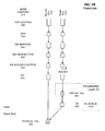
- FIG. 10 is a diagram of an exemplary flow of I/O requests during a final state of encapsulation, consistent with an embodiment of the present invention.
- FIG. 11 is diagram of exemplary states in a de-encapsulation process, consistent with an embodiment of the present invention.
- FIG. 12 is diagram of an exemplary flow of I/O requests at the completion of a set up state of de-encapsulation, consistent with an embodiment of the present invention.
- the inventors of the present invention recognized that the present invention may be implemented, among other ways, as a filter driver in the I/O stack.
- the POWERPATH tool available by EMC Corporation of Hopkinton, Mass., is an example of an I/O filter driver.
- the invention is implemented as an extension to the POWERPATH tool.
- filter driver 40 can conceptually be considered to be placed between OS 43 and at least one host bus adapter 45 , such as host bus adapter 15 in FIG. 1 .
- a data storage system such as storage system 3 in FIG. 1 , presents volumes of data storage to the host computer for assignment to various resources therein, such as to provide storage space for a file system, an LVM, or a database. Volumes are presented via signals arriving at the collection of host bus adapters 45 on the host. These signals are processed by filter driver 40 , which creates a volume representation 60 . Functionality may be attributed to the volume representation.
- Filter driver 40 of FIG. 2 may be thought of conceptually as having the form of a “C” clamp with a top horizontal arm 47 , a bottom horizontal arm 49 , and a vertical connector 51 between the arms.
- Horizontal arm 47 may be, for example, an interface to any operating system (OS) such as Sun's SOLARIS, LINUX, and Microsoft's WINDOWS NT.
- Bottom horizontal arm 49 includes platform-dependent code comprising an interface 48 to relevant host bus adapters.
- Vertical connector 51 comprises a series of common Application Programming Interfaces (APIs).
- APIs Application Programming Interfaces
- An extension stack 53 is enveloped between arms 47 and 49 .
- a DM extension 59 is added in the embodiment of FIG. 2 to manage I/O requests during a data encapsulation or de-encapsulation process.
- DM extension 59 can consist of a plurality of extensions.
- DM extension 59 , or portions thereof, may also be used during a data migration process.
- the software architecture of virtualization layer 70 can be viewed as consisting of a SCSI virtualization layer 71 , a volume virtualization layer 72 , and a back-end services layer 73 .
- SCSI virtualization layer 71 is responsible for presenting virtual storage volumes, such as volume 74 to the at least one host bus adaptor 45 via an interface 75 .
- Volume virtualization layer 72 creates virtual volumes by composing at least one storage element 76 .
- Back-end services layer 73 imports physical storage and creates the at least one storage element 76 .
- FIG. 3A illustrates exemplary architecture for managing I/O requests during encapsulation or de-encapsulation.
- FIG. 3A includes at least one host computer 1 , a boot device 110 , a network 150 , a physical volume 300 and a virtual volume 350 that may be presented to host computer 1 .
- Physical volume 300 provides data storage. Physical volume 300 may be anything from a simple data storage device to a complex system that provides data storage, such as a FAStT data storage system from IBM, a TagmaStore data storage system from HDS, or a CLARIION or SYMMETRIX data storage system from EMC Corporation.
- Network 150 enables communication between host computer 1 , physical volume 300 , and virtual volume 350 .
- Network 150 may also enable communication between host computer 1 and boot device 110 .
- Network 150 may be, for example, a Fibre Channel fabric.
- network 150 may include, among other components, SCSI buses 17 , 18 and SCSI drivers 9 , 10 , 15 all of FIG. 1 .
- Host computer 1 uses physical volume 300 to store data. Physical volume 300 , including the data contained therein, can be encapsulated in virtual volume 350 . Prior to encapsulation of physical volume 300 , host 1 uses link 310 to access data on volume 300 . Links 320 and 330 in FIG. 3A may not exist. After encapsulation, host 1 uses link 320 in FIG. 3A to access data on physical volume 300 only via virtual volume 350 and link 330 . Link 310 in FIG. 3A may not exist.
- Virtualization layer 70 can present virtual volume 350 with storage provided by physical volume 300 to host 1 .
- host computer 1 can store data about the state and/or status of the process in boot device 110 .
- This metadata may be stored in the boot device 110 , for example, as kernel metadata or user metadata. Storing kernel and/or user metadata can enable the process to resume in the same state after either a crash or a graceful shutdown and restart during the encapsulation or de-encapsulation process.
- boot device 110 must be the first device the host computer accesses during the host boot process. Accordingly, the host computer 1 may enable the kernel state of the process to be restored during a reboot.
- FIG. 3B illustrates an exemplary block storage virtualization layer 70 in the context of the exemplary architecture of FIG. 3A .
- Virtualization Layer 70 is interposed between host 1 and physical volume 300 when physical volume 300 is encapsulated.
- Virtualization layer 70 includes a switch 356 , a storage processor 354 , and metadata storage 358 .
- Switch 356 can be, for example, a Brocade AP7420 or a Cisco MDS 9500 series switch.
- Storage processor 354 controls switch 356 , for example, using data stored on metadata storage 358 and virtualization software.
- the virtualization software may be, for example, INVISTA software available from EMC Corporation of Hopkinton, Mass.
- Metadata storage 358 may be any memory device capable of storing data about the characteristics of physical volume 300 and its presentation to host 1 .
- block storage virtualization layer 70 may be implemented as described in U.S. Pat. No. 7,206,863, entitled “System And Method For Managing Storage Networks And Providing Virtualization Of Resources In Such A Network” and issued on Apr. 17, 2007 to assignee EMC Corp.
- FIG. 4 is a diagram 400 of exemplary states in a process for encapsulating a physical volume in a virtual volume, consistent with an embodiment of the present invention.
- host applications access data in the physical volume with a source user device name.
- a user can control transitions between different stages in the encapsulation process, using among other things a program running in user space and filter driver 40 .
- the stages are referred to as “states.” Changing from one state to another state is referred to as a “state transition.”
- arrows represent possible state transitions that may occur during encapsulation.
- Initial state 410 of FIG. 4 is a state that exists prior to any encapsulation operation.
- Setup state 420 is reached after the user issues a command, such as a SETUP command, to begin the encapsulation process.
- a command such as a SETUP command
- all preparation required before encapsulation of a physical logical unit as a target virtual logical unit is completed.
- Setup state 420 may also be reached as a result of aborting an encapsulation. From setup state 420 , the user has the choice of continuing to a source selected state 440 , or returning to an initial state 410 , which eliminates the state changes that were made to reach setup state 420 .
- an intermediate state 430 that enables a target volume to synchronize with a source volume may exist between the setup state 420 and the source selected state 440 .
- DM extension 59 may confirm that the target volume and the source volume store the same data before transitioning to a source selected state 440 .
- the source selected state 440 in the encapsulation process is reached after the user issues a command, such as a SYNC command, to initiate a transition from the setup state 420 to the next state in the encapsulation process.
- a command such as a SYNC command
- data in the physical volume may only be accessed via the source logical unit.
- the user may choose to return to setup state 420 .
- the user may issue a command to move to a target selected state 450 .
- Target selected state 450 is reached after the user issues a command, such as a SELECT TARGET command, to initiate a transition from the source selected state 440 to the next state in the encapsulation process.
- a command such as a SELECT TARGET command
- data in the physical volume may only be accessed via the virtual volume.
- the user may choose to return to source selected state 440 or to setup state 420 .
- the user may issue a command to move to a committed state 460 .
- committed state 460 is reached after the user issues a command, such as a COMMIT command, to initiate a transition from the target selected state 450 to the next state in the encapsulation process.
- a command such as a COMMIT command
- data in the physical volume may no longer be accessed directly via the physical volume.
- the encapsulation process cannot be aborted from committed state 460 .
- the user may issue the commit command after he is satisfied with an evaluation of the virtual volume.
- Final state 470 is reached after the user issues a command, such as a CLEANUP command, to initiate a transition from the committed state 460 to the next state in the encapsulation process.
- a command such as a CLEANUP command
- the system verifies that the physical volume is no longer accessible to the host. If it finds that it is still accessible, the cleanup will fail and the encapsulation process will remain in the committed state.
- the committed state access to the source volume is prevented by the DM extension. This access control must remain in place until the source volume has been physically removed from the host.
- various commands may be issued by the user to transition from one state to another. State transitions can be initiated by additional commands available to the user. For example, a user may issue a command, such as the SELECT SOURCE command, to initiate the transition from target selected state 450 to source selected state 440 . Furthermore, a user may issue a command to initiate the transition from any state in FIG. 4 except committed state 460 and final state 470 back to setup state 420 . A transition back to setup state 420 may be considered an abort of the encapsulation process.
- a command such as the SELECT SOURCE command
- the encapsulation process states illustrated in FIG. 4 can be related to links conceptually illustrated in FIG. 3A .
- link 310 makes data on physical volume 300 accessible to the host 1 , but links 320 and 330 do not exist.
- links 320 and 330 make data on physical volume 300 accessible to host 1 , but link 310 does not exist.
- the links are configured and checked while I/O requests are managed to protect the data on physical volume 300 and minimize the disruption required by the encapsulation process.
- the system architecture may alternatively include a direct connection of links 310 and 320 to host 1 and not through SAN 150 .
- Table 1 summarizes exemplary management of I/O requests in various layers during various states in the encapsulation process identified in FIG. 4 .
- the first two rows of Table 1 refer to management in host computer 1 , which may be implemented in filter driver 40 .
- the last row of Table 1 refers to management in virtualization layer 70 .
- FIGS. 5-10 elaborate on Table 1 and illustrate exemplary flows of I/O requests during various states identified in FIG. 4 .
- FIGS. 5-11 each illustrate the same levels in the flow of I/O requests. Each of the illustrated levels, however, may not be relevant to any single state.
- FIG. 5 is a flow diagram conceptually illustrating exemplary management of I/O requests at various layers in initial state 410 of FIG. 4 , consistent with an embodiment of the present invention.
- source user device 512 represents one or more ways that physical volume 300 may be addressed by a host I/O request.
- physical volume 300 may be addressed with a native name or a pseudo name.
- U.S. patent application Ser. No. 11/427,889 which is entitled “Methods And Systems For Migrating Data With Minimal Disruption” and which was filed on Jun. 30, 2006, naming M. Bappe and H. Raizen as inventors—discloses methods and systems whereby I/O requests can reach a data storage volume using a pseudo name.
- Layers 520 , 530 , and 570 in FIG. 5 are each managed by one or more existing extensions 61 , 57 of the extension stack 53 shown in FIG. 2 in this exemplary embodiment.
- Layer 520 of FIG. 5 represents a first layer at which I/O requests addressed to a physical volume 300 may be suspended. Suspended I/O requests may be queued so that they can be executed when an appropriate state has been reached.
- Layer 530 of FIG. 5 represents a mapping layer.
- Layer 530 in initial state 410 may map a pseudo and/or native name—used by a host application in level 510 to access data on physical volume 300 —to an inherent device identifier of a data storage volume or of a physical connection to a data storage volume.
- Layer 530 enables host 1 to address physical volume 300 with a pseudo name and/or native names.
- Layers 540 , 550 , and 560 may be managed by DM extension 59 of FIG. 2 in the exemplary embodiment. To increase the processing speed, I/O requests need not flow through layers 540 , 550 , and 560 prior to the initiation of an encapsulation process.
- Layer 570 in FIG. 5 represents a multipath layer.
- layer 570 maps I/O requests that were on paths addressed by a native or pseudo name to physical volume 300 .
- layer 570 routes I/O requests that were on paths addressed by a native or pseudo name to physical volume 300 .
- a physical volume 300 is illustrated.
- FIG. 6A is a flow diagram conceptually illustrating exemplary management of I/O requests at various layers in set up state 420 of FIG. 4 , consistent with an embodiment of the present invention.
- a physical volume 300 is illustrated with a potential I/O request pathway via virtual volume 350 .
- virtualization layer 70 has been configured to prepare for host access to data on the physical volume 300 via virtual volume 350 .
- the portion of the flow diagram labeled “Virtualization Layer” is not part of the host, but may be, for example, block storage virtualization layer 70 .
- Setup state 420 is reached, for example, after a SET UP command, which is initiated by a user, initializes an encapsulation operation.
- physical volume 300 and virtual volume 350 are identified.
- a representation of physical volume 300 is imported into the virtualization layer as a storage element 590 .
- the virtualization layer stores identifying information associated with storage element 590 such as its array identifier, its volume identifier, its capacity, and/or its firmware level.
- Storage element 590 logically references the volume, V, that it consumes without providing any additional data storage.
- Virtualization layer 70 may also associate a new attribute with storage element 590 and gives the attribute a protection value, such as NOT READY.
- a virtual volume V′ also referred to as virtual volume 350 , is created to encapsulate storage element 590 .
- virtual volume V′ is presented to host 1 as a target user device 516 .
- the system in set up state 420 is configured to prepare for the flow shown on the right side of FIG. 6A .
- target user device 516 represents one way that virtual volume 350 may be addressed by a host I/O request.
- virtual volume 350 may be addressed with a native name or a pseudo name.
- I/O requests in layers 510 , 520 , 530 , and 570 of FIG. 6A are managed similarly to I/O requests in layers 510 , 520 , 530 , and 570 of FIG. 5 .
- Layer 540 of FIG. 6A represents a second layer at which I/O requests addressed to a data storage volume may be suspended and later resumed.
- Layer 540 is used to transition between different states, such as initial state 410 and set up state 420 .
- a state change is initiated, for example, by issuing a state change command such as a SET UP command.
- Layer 540 allows I/O requests that are pending before a state change is initiated to execute. I/O requests that arrive after a state change is initiated, however, are queued in layer 540 so that they can be executed when an appropriate state has been reached. In any of the states such as setup state 420 , I/O requests are not suspended in layer 540 .
- Layer 550 of FIG. 6A represents a layer at which I/O requests may be redirected from one volume of data to another. In setup state 420 , I/O requests are not redirected in layer 550 .
- Layer 560 of FIG. 6A represents a layer at which I/O requests may be prevented from accessing a data storage volume.
- I/O requests may be prevented from accessing virtual volume 350 in layer 560 .
- Access control is useful to prevent the host from accessing data both through virtual volume 350 and physical volume 300 directly. If such situation does occur, the host operating system and applications may become confused.
- the protection state of the attribute associated with storage element 590 may also be used to prevent access to physical volume 300 via virtual volume 350 .
- host computer 1 Prior to transitioning to SETUP state 420 , host computer 1 confirms that the encapsulation process is ready to move forward. For example, the exemplary embodiment confirms that the array identifier, the volume identifier, the capacity, and/or the firmware level of the storage element 590 match that of physical volume 300 . The exemplary embodiment may further confirm that the value of the new attribute for the storage element is NOT READY. The exemplary embodiment may also confirm that virtual volume 350 is a one-to-one representation of the storage element 590 .
- FIG. 6B is a flow diagram conceptually illustrating exemplary management of I/O requests at various layers in optional transition state 430 of FIG. 4 , consistent with an embodiment of the present invention.
- I/O requests are prevented from accessing virtual volume 350 in layer 560 .
- the SE attribute of the volume has a TEST value.
- the TEST attribute value allows I/Os to be issued to the volume from the host, but prevents the addition of network virtualization features to the volume that would move data from the physical volume 300 . In other words, the data on physical volume 300 continues to reside there and cannot be moved during the encapsulation process while the SE is in TEST attribute value.
- FIG. 7 is a flow diagram conceptually illustrating exemplary management of I/O requests at various layers in source selected state 440 of FIG. 4 , consistent with an embodiment of the present invention.
- Source selected state 440 is reached, for example, after a SYNC command.
- the command to transition to source selected state 440 may initiate two changes: (1) it ensures that access control layer 560 prevents access to virtual volume 350 ; and (2) it causes virtualization layer 70 to set the SE attribute to the TEST value.
- one or more of the foregoing changes may be made prior to moving to source selected state 440 .
- I/O requests in source selected state 440 is illustrated beginning at layer 510 in FIG. 7 .
- I/O requests in most layers of FIG. 7 are managed similarly to I/O requests in the corresponding layers of FIG. 6A .
- access control layer 560 may or may not allow I/O requests in set up state 420 to proceed to virtual volume 350
- access control layer 560 does not allow I/O requests in source selected state 440 to proceed to virtual volume 350 .
- FIG. 8 is a flow diagram conceptually illustrating exemplary management of I/O requests at various layers in target selected state 450 of FIG. 4 , consistent with an embodiment of the present invention.
- the target selected state 450 illustrated in FIG. 8 can be reached, for example, after a SETUP command specifying encapsulation, a SYNC command, and a TARGET SELECT command are issued.
- I/O requests in layers 510 , 520 , 530 , 540 , and 570 of FIG. 8 are managed similarly to I/O requests in layers 510 , 520 , 530 , 540 , and 570 of FIG. 7 .
- I/O requests that had been directed to physical volume 300 such as by user device name 512
- any I/O requests that had been directed to virtual volume 350 such as by user device name 516
- no I/O requests should be directed to virtual volume 350 such cross-redirection in level 550 prevents accidental data corruption by enabling any such I/O requests to be easily handled in level 560 .
- I/O requests are prevented from accessing physical volume 300 .
- I/O requests following a path to virtual volume 350 in layer 540 of FIG. 8 are redirected in layer 550 , then prevented from accessing any logical unit in layer 560 .
- Layer 550 enables the transition—from direct access to access via virtual volume 350 —to be less disruptive to a host trying to encapsulate data stored in the physical volume 300 .
- FIG. 9 is a flow diagram conceptually illustrating exemplary management of I/O requests at various layers in committed state 460 of FIG. 4 , consistent with an embodiment of the present invention.
- committed state 460 illustrated in FIG. 9 the redirection that existed in layer 550 in target selected state 450 is eliminated.
- layer 530 maps source user device 512 to the device identifier of virtual volume 350 , which was previously mapped to target user device 516 .
- Layer 530 may also map target user device 516 to the device identifier of physical volume 300 , which was previously mapped to source user device 512 .
- Committed state 460 is reached after the user issues a command, such as a COMMIT command, to transition from the target selected state 450 to the next state in the encapsulation process.
- a command such as a COMMIT command
- the new attribute for storage element 590 in virtualization layer 70 is set to a NORMAL value.
- the NORMAL attribute value allows the virtualization layer 70 to move data from physical volume 300 to another physical volume.
- FIG. 10 is a flow diagram conceptually illustrating exemplary management of I/O requests at various layers in final state 470 of FIG. 4 , consistent with an embodiment of the present invention.
- Final state 470 is reached after the user issues a command, such as a CLEANUP command, to transition from committed state 460 to the next state in the encapsulation process.
- a command such as a CLEANUP command
- any physical connection to physical volume 300 at host 1 is eliminated. Any data or metadata from physical volume 300 that might be cached on the host and cause OS or application confusion or errors is removed from the host.
- Mapping of target user device 516 to the inherent device identifier of physical volume 300 in layer 530 is eliminated. Additionally, mapping in multipath layer 570 directly to physical volume 300 is eliminated.
- access control in level 560 can be disabled.
- FIG. 11 is a diagram 1100 of exemplary states in a process for de-encapsulating a physical volume 300 that is encapsulated with a virtual volume 350 , consistent with an embodiment of the present invention.
- Initial state 1110 of FIG. 11 is a state that exists before the de-encapsulation process has begun.
- a host accesses data in the physical volume 300 via the virtual volume 350 with a user device name 512 .
- arrows represent possible state transitions that may occur during de-encapsulation.
- the SE attribute of the SE underlying virtual volume 350 is NORMAL.
- Setup state 1120 is reached after a user issues a command, such as the SETUP command, to begin the de-encapsulation process. In the transition from the initial state 1110 to setup state 1120 , some preparation required to de-encapsulate the physical volume is done. Prior to setup state 1120 , the virtual volume 350 and physical volume 300 are identified. All data to be directly accessed on physical volume 300 at the completion of the de-encapsulation process must reside on that volume by the set-up state 1120 .
- FIG. 12 is a flow diagram conceptually illustrating exemplary management of I/O requests at various layers in set up state 1120 of FIG. 11 , consistent with an embodiment of the present invention.
- Embodiments of the present invention may include several intermediate phases between initial state 1110 and setup state 1120 .
- the virtual volume may be prepared for de-encapsulation.
- virtualization layer 70 may simply check that all of the data on virtual volume 350 is on a single physical volume 300 .
- virtualization layer 70 may move all of the data on virtual volume 350 onto a single physical volume 300 .
- virtualization layer 70 may prevent data on the single physical volume 300 from being moved to another physical volume. This may be done, for example as illustrated in FIG. 12 , by setting an attribute associated with storage element 590 in virtualization layer 70 to a TEST state.
- information about the physical volume 300 underlying virtual volume 350 may be collected by filter driver 40 from virtualization layer 70 .
- information about the physical volume 300 underlying virtual volume 350 may include information associated with storage element 590 such as its array identifier, its volume identifier, its capacity, and/or its firmware level.
- filter driver 40 may prevent direct access to physical volume 300 . This may be done, for example as illustrated in FIG. 12 , by setting an attribute in layer 560 that is associated with an identifier of physical volume to a protection value, thereby preventing I/O requests from accessing a physical volume 300 . Access control is useful to prevent the host from accessing data both through virtual volume 350 and physical volume 300 directly. If such situation does occur, the host operating system and applications may become confused. Controlling host access to physical volume 300 before direct access to physical volume 300 is even possible may avoid problems in the de-encapsulation process for which no means for avoidance have previously been presented.
- FIG. 12 illustrates the completed setup state 1120 .
- filter driver 40 chooses target user device 516 based on identifying information associated with storage element 590 .
- setup state 1120 the user has the choice of continuing to a virtual volume selected state 1140 , or returning to an initial state 1110 , which eliminates the state changes that were made to reach setup state 1120 . Additionally, setup state 1120 may also be reached as a result of aborting a de-encapsulation process.
- the virtual volume selected state 1140 is reached after a command initiates a transition from the setup state 1120 to the next state in the de-encapsulation process.
- the TEST state allows I/Os to be issued to the volume from the host, but prevents the prevents virtualization layer 70 from moving data from physical volume 300 to another physical volume.
- data in the encapsulated physical volume 300 is accessed via virtual volume 350 .
- the user may choose to return to setup state 1120 .
- the user may issue a command to move to a physical volume selected state 1150 .
- Physical volume selected state 1150 is reached after a command initiates a transition from virtual volume selected state 1140 to the next state in the de-encapsulation process. In physical volume selected state 1150 , data in the physical volume may only be accessed directly.
- the user may choose to return to virtual volume selected state 1140 or setup state 1120 .
- the user may issue a command to move to a committed state 1160 .
- the de-encapsulation process on the host sets the state of the attribute associated with storage element 590 to NOT READY.
- Committed state 1160 is reached after a command initiates a transition from physical volume selected state 1150 to the next state in the de-encapsulation process.
- committed state 1160 data in the physical volume may no longer be accessed via the virtual volume. Thus, the de-encapsulation process cannot be aborted from committed state 1160 .
- the user may issue the COMMIT command after he is satisfied with an evaluation of direct access to the physical volume.
- Final state 1170 in the de-encapsulation process 1100 is reached after a command, such as the CLEANUP command, initiates a transition from committed state 1160 to the next state in the de-encapsulation process.
- the CLEANUP command verifies that virtual volume 350 is not accessible to host 1 . If it is accessible, the CLEANUP command will fail and the de-encapsulation process will remain in the COMMITTED state. Being in the COMMITTED state includes preventing access to virtual volume 350 through the access control mechanism.
- storage element 590 in virtualization layer 70 and the associated attributes are eliminated.
- the de-encapsulation process states illustrated in FIG. 11 can be related to links conceptually illustrated in FIG. 3A .
- links 320 and 330 Prior to the initial state 1110 , links 320 and 330 make data on physical volume 300 accessible to host 1 , but link 310 does not exist.
- link 310 After the final state 1170 , link 310 makes data on physical volume 300 accessible to the host 1 but links 320 and 330 do not exist.
- the links are configured and checked while I/O requests are managed to protect the data on physical volume 300 and minimize the disruption required by the de-encapsulation process.
- the system architecture may alternatively include a direct connection of links 310 and 320 to host 1 and not through SAN 150 .
- Table 2 summarizes exemplary management of I/O requests in various layers during states in the de-encapsulation process identified in FIG. 11 .
- the first two rows of Table 1 refer to management in host computer 1 , which may be implemented in filter driver 40 .
- the last row of Table 1 refers to management in virtualization layer 70 .
- Programs based on the written description and methods of this invention are within the skill of an experienced developer.
- the various programs or program modules can be created using any of the techniques known to one skilled in the art or can be designed in connection with existing software.
- program sections or program modules can be designed in or by means of Java, C, C++, HTML, XML, or HTML with included Java applets.
- One or more of such software sections or modules can be integrated into a computer system.
Abstract
Description
| TABLE 1 |
| Exemplary Management of I/O Requests |
| in Different States in the Encapsulation Process |
| Source | Target | ||||
| STATE | Setup | Selected | Selected | Committed | Final |
| Redirection | none | none | cross | none | none |
| (2-way) | |||||
| redirection | |||||
| Access Control | none | Virtual | Physical | Physical | none |
| Volume | volume | volume | |||
| SE Attribute | Not Ready | Test | Test | Normal | Normal |
| TABLE 2 |
| Exemplary Management of I/O Requests |
| in Different States in the De-Encapsulation Process |
| Virtual | Physical | |||||
| Vol. | Vol. | Com- | ||||
| STATE | Initial | Setup | Selected | Selected | mitted | Final |
| Redirection | none | none | none | cross | none | none |
| (2-way) | ||||||
| redirection | ||||||
| Access | none | physical | physical | virtual | virtual | none |
| Control | vol. | vol. | volume | volume | ||
| SE | Normal | Test | Test | Test | Not | N/A |
| Attribute | Ready | |||||
Claims (11)
Priority Applications (1)
| Application Number | Priority Date | Filing Date | Title |
|---|---|---|---|
| US11/863,745 US8332613B1 (en) | 2006-09-29 | 2007-09-28 | Methods and systems for managing I/O requests to minimize disruption required for data encapsulation and de-encapsulation |
Applications Claiming Priority (2)
| Application Number | Priority Date | Filing Date | Title |
|---|---|---|---|
| US11/536,995 US7809912B1 (en) | 2006-09-29 | 2006-09-29 | Methods and systems for managing I/O requests to minimize disruption required for data migration |
| US11/863,745 US8332613B1 (en) | 2006-09-29 | 2007-09-28 | Methods and systems for managing I/O requests to minimize disruption required for data encapsulation and de-encapsulation |
Related Parent Applications (1)
| Application Number | Title | Priority Date | Filing Date |
|---|---|---|---|
| US11/536,995 Continuation-In-Part US7809912B1 (en) | 2006-09-29 | 2006-09-29 | Methods and systems for managing I/O requests to minimize disruption required for data migration |
Publications (1)
| Publication Number | Publication Date |
|---|---|
| US8332613B1 true US8332613B1 (en) | 2012-12-11 |
Family
ID=47289252
Family Applications (1)
| Application Number | Title | Priority Date | Filing Date |
|---|---|---|---|
| US11/863,745 Active 2029-10-29 US8332613B1 (en) | 2006-09-29 | 2007-09-28 | Methods and systems for managing I/O requests to minimize disruption required for data encapsulation and de-encapsulation |
Country Status (1)
| Country | Link |
|---|---|
| US (1) | US8332613B1 (en) |
Cited By (7)
| Publication number | Priority date | Publication date | Assignee | Title |
|---|---|---|---|---|
| US20130054846A1 (en) * | 2011-08-31 | 2013-02-28 | International Business Machines Corporation | Non-disruptive configuration of a virtualization cotroller in a data storage system |
| US8819307B1 (en) | 2011-12-29 | 2014-08-26 | Emc Corporation | Identification and use of preferred path groups in host computer based on differential performance |
| US8826041B1 (en) | 2011-03-30 | 2014-09-02 | Emc Corporation | In-band detection mechanism for detecting intermediate layer in a storage I/O driver stack |
| US20150127861A1 (en) * | 2013-11-06 | 2015-05-07 | International Business Machines Corporation | Dynamic Data Collection Communication Between Adapter Functions |
| US10032041B2 (en) | 2015-05-30 | 2018-07-24 | Apple Inc. | Storage volume protection using restricted resource classes |
| WO2019150287A1 (en) * | 2018-01-30 | 2019-08-08 | Encapsa Technology Llc | Method and system for encapsulating and storing information from multiple disparate data sources |
| US20200034240A1 (en) * | 2018-07-30 | 2020-01-30 | EMC IP Holding Company LLC | Network block device based continuous replication for kubernetes container management systems |
Citations (22)
| Publication number | Priority date | Publication date | Assignee | Title |
|---|---|---|---|---|
| US5742792A (en) | 1993-04-23 | 1998-04-21 | Emc Corporation | Remote data mirroring |
| US6564336B1 (en) | 1999-12-29 | 2003-05-13 | General Electric Company | Fault tolerant database for picture archiving and communication systems |
| US20030226059A1 (en) | 2002-05-30 | 2003-12-04 | Braun Richard A. | Systems and methods for remote tracking of reboot status |
| US20040080558A1 (en) | 2002-10-28 | 2004-04-29 | Blumenau Steven M. | Method and apparatus for monitoring the storage of data in a computer system |
| US6745306B1 (en) * | 1999-07-29 | 2004-06-01 | Microsoft Corporation | Method and system for restricting the load of physical address translations of virtual addresses |
| US6845403B2 (en) * | 2001-10-31 | 2005-01-18 | Hewlett-Packard Development Company, L.P. | System and method for storage virtualization |
| US6857059B2 (en) * | 2001-01-11 | 2005-02-15 | Yottayotta, Inc. | Storage virtualization system and methods |
| US20050235132A1 (en) * | 2003-11-26 | 2005-10-20 | Veritas Operating Corporation | System and method for dynamic LUN mapping |
| US7076690B1 (en) | 2002-04-15 | 2006-07-11 | Emc Corporation | Method and apparatus for managing access to volumes of storage |
| US7080221B1 (en) | 2003-04-23 | 2006-07-18 | Emc Corporation | Method and apparatus for managing migration of data in a clustered computer system environment |
| US7080225B1 (en) | 2002-12-10 | 2006-07-18 | Emc Corporation | Method and apparatus for managing migration of data in a computer system |
| US7093088B1 (en) | 2003-04-23 | 2006-08-15 | Emc Corporation | Method and apparatus for undoing a data migration in a computer system |
| US7281102B1 (en) * | 2004-08-12 | 2007-10-09 | Vmware, Inc. | Restricting memory access to protect data when sharing a common address space |
| US7281124B2 (en) * | 2004-06-17 | 2007-10-09 | Intel Corporation | Establishing a virtual drive accessible to pre-boot and operating system runtime phases |
| US20080155169A1 (en) * | 2006-12-21 | 2008-06-26 | Hiltgen Daniel K | Implementation of Virtual Machine Operations Using Storage System Functionality |
| US7478221B1 (en) * | 2005-05-03 | 2009-01-13 | Symantec Operating Corporation | System and method for using consistent virtual addresses to communicate in cooperative multi-layer virtualization environments |
| US7770059B1 (en) * | 2004-03-26 | 2010-08-03 | Emc Corporation | Failure protection in an environment including virtualization of networked storage resources |
| US7774514B2 (en) * | 2005-05-16 | 2010-08-10 | Infortrend Technology, Inc. | Method of transmitting data between storage virtualization controllers and storage virtualization controller designed to implement the method |
| US7818517B1 (en) * | 2004-03-26 | 2010-10-19 | Emc Corporation | Architecture for virtualization of networked storage resources |
| US7849262B1 (en) * | 2000-06-30 | 2010-12-07 | Emc Corporation | System and method for virtualization of networked storage resources |
| US7937700B1 (en) * | 2004-05-11 | 2011-05-03 | Advanced Micro Devices, Inc. | System, processor, and method for incremental state save/restore on world switch in a virtual machine environment |
| US8074045B2 (en) * | 2008-05-30 | 2011-12-06 | Vmware, Inc. | Virtualization with fortuitously sized shadow page tables |
-
2007
- 2007-09-28 US US11/863,745 patent/US8332613B1/en active Active
Patent Citations (24)
| Publication number | Priority date | Publication date | Assignee | Title |
|---|---|---|---|---|
| US5742792A (en) | 1993-04-23 | 1998-04-21 | Emc Corporation | Remote data mirroring |
| US6745306B1 (en) * | 1999-07-29 | 2004-06-01 | Microsoft Corporation | Method and system for restricting the load of physical address translations of virtual addresses |
| US6564336B1 (en) | 1999-12-29 | 2003-05-13 | General Electric Company | Fault tolerant database for picture archiving and communication systems |
| US7849262B1 (en) * | 2000-06-30 | 2010-12-07 | Emc Corporation | System and method for virtualization of networked storage resources |
| US6857059B2 (en) * | 2001-01-11 | 2005-02-15 | Yottayotta, Inc. | Storage virtualization system and methods |
| US6845403B2 (en) * | 2001-10-31 | 2005-01-18 | Hewlett-Packard Development Company, L.P. | System and method for storage virtualization |
| US7076690B1 (en) | 2002-04-15 | 2006-07-11 | Emc Corporation | Method and apparatus for managing access to volumes of storage |
| US20030226059A1 (en) | 2002-05-30 | 2003-12-04 | Braun Richard A. | Systems and methods for remote tracking of reboot status |
| US20040080558A1 (en) | 2002-10-28 | 2004-04-29 | Blumenau Steven M. | Method and apparatus for monitoring the storage of data in a computer system |
| US7080225B1 (en) | 2002-12-10 | 2006-07-18 | Emc Corporation | Method and apparatus for managing migration of data in a computer system |
| US7080221B1 (en) | 2003-04-23 | 2006-07-18 | Emc Corporation | Method and apparatus for managing migration of data in a clustered computer system environment |
| US7093088B1 (en) | 2003-04-23 | 2006-08-15 | Emc Corporation | Method and apparatus for undoing a data migration in a computer system |
| US20050235132A1 (en) * | 2003-11-26 | 2005-10-20 | Veritas Operating Corporation | System and method for dynamic LUN mapping |
| US7818517B1 (en) * | 2004-03-26 | 2010-10-19 | Emc Corporation | Architecture for virtualization of networked storage resources |
| US7770059B1 (en) * | 2004-03-26 | 2010-08-03 | Emc Corporation | Failure protection in an environment including virtualization of networked storage resources |
| US7984253B1 (en) * | 2004-03-26 | 2011-07-19 | Emc Corporation | Architecture for virtualization of networked storage resources |
| US7992038B1 (en) * | 2004-03-26 | 2011-08-02 | Emc Corporation | Failure protection in an environment including virtualization of networked storage resources |
| US7937700B1 (en) * | 2004-05-11 | 2011-05-03 | Advanced Micro Devices, Inc. | System, processor, and method for incremental state save/restore on world switch in a virtual machine environment |
| US7281124B2 (en) * | 2004-06-17 | 2007-10-09 | Intel Corporation | Establishing a virtual drive accessible to pre-boot and operating system runtime phases |
| US7281102B1 (en) * | 2004-08-12 | 2007-10-09 | Vmware, Inc. | Restricting memory access to protect data when sharing a common address space |
| US7478221B1 (en) * | 2005-05-03 | 2009-01-13 | Symantec Operating Corporation | System and method for using consistent virtual addresses to communicate in cooperative multi-layer virtualization environments |
| US7774514B2 (en) * | 2005-05-16 | 2010-08-10 | Infortrend Technology, Inc. | Method of transmitting data between storage virtualization controllers and storage virtualization controller designed to implement the method |
| US20080155169A1 (en) * | 2006-12-21 | 2008-06-26 | Hiltgen Daniel K | Implementation of Virtual Machine Operations Using Storage System Functionality |
| US8074045B2 (en) * | 2008-05-30 | 2011-12-06 | Vmware, Inc. | Virtualization with fortuitously sized shadow page tables |
Non-Patent Citations (8)
| Title |
|---|
| EMC Corporation, EMC Invista Deployment Scenarios, by M. Waxman and B. Carr, EMC World Boston 2006, 31 pages. |
| EMC Corporation, Non-disruptive Data Migration with PowerPath Migration Enabler-a breakthrough technology from EMC, by J. Crum and H. Raizen, EMC World Boston 2006, 26 pages. |
| U.S. Appl. No. 10/211,469. |
| U.S. Appl. No. 10/351,791. |
| U.S. Appl. No. 10/353,322. |
| U.S. Appl. No. 11/536,995, filed Sep. 29, 2006. |
| U.S. Appl. No. 11/536,995, Helen S. Raizen, et al., filed Sep. 29, 2006. |
| U.S. Appl. No. 11/607,067, Michael E. Bappe et al., filed Dec. 1, 2006. |
Cited By (15)
| Publication number | Priority date | Publication date | Assignee | Title |
|---|---|---|---|---|
| US8826041B1 (en) | 2011-03-30 | 2014-09-02 | Emc Corporation | In-band detection mechanism for detecting intermediate layer in a storage I/O driver stack |
| US20130054846A1 (en) * | 2011-08-31 | 2013-02-28 | International Business Machines Corporation | Non-disruptive configuration of a virtualization cotroller in a data storage system |
| US8713218B2 (en) * | 2011-08-31 | 2014-04-29 | International Business Machines Corporation | Non-disruptive configuration of a virtualization controller in a data storage system |
| US8996758B2 (en) | 2011-08-31 | 2015-03-31 | International Business Machines Corporation | Non-disruptive configuration of a virtualization controller in a data storage system |
| US9262087B2 (en) | 2011-08-31 | 2016-02-16 | International Business Machines Corporation | Non-disruptive configuration of a virtualization controller in a data storage system |
| US8819307B1 (en) | 2011-12-29 | 2014-08-26 | Emc Corporation | Identification and use of preferred path groups in host computer based on differential performance |
| US20150347347A1 (en) * | 2013-11-06 | 2015-12-03 | International Business Machines Corporation | Dynamic Data Collection Communication Between Adapter Functions |
| US20150127861A1 (en) * | 2013-11-06 | 2015-05-07 | International Business Machines Corporation | Dynamic Data Collection Communication Between Adapter Functions |
| US9514087B2 (en) * | 2013-11-06 | 2016-12-06 | International Business Machines Corporation | Dynamic data collection communication between adapter functions |
| US9552324B2 (en) * | 2013-11-06 | 2017-01-24 | International Business Machines Corporation | Dynamic data collection communication between adapter functions |
| US10032041B2 (en) | 2015-05-30 | 2018-07-24 | Apple Inc. | Storage volume protection using restricted resource classes |
| WO2019150287A1 (en) * | 2018-01-30 | 2019-08-08 | Encapsa Technology Llc | Method and system for encapsulating and storing information from multiple disparate data sources |
| US11507556B2 (en) * | 2018-01-30 | 2022-11-22 | Encapsa Technology Llc | Method and system for encapsulating and storing information from multiple disparate data sources |
| US20200034240A1 (en) * | 2018-07-30 | 2020-01-30 | EMC IP Holding Company LLC | Network block device based continuous replication for kubernetes container management systems |
| US10908999B2 (en) * | 2018-07-30 | 2021-02-02 | EMC IP Holding Company LLC | Network block device based continuous replication for Kubernetes container management systems |
Similar Documents
| Publication | Publication Date | Title |
|---|---|---|
| US7809912B1 (en) | Methods and systems for managing I/O requests to minimize disruption required for data migration | |
| US9645764B2 (en) | Techniques for migrating active I/O connections with migrating servers and clients | |
| US7624262B2 (en) | Apparatus, system, and method for booting using an external disk through a virtual SCSI connection | |
| US9928091B2 (en) | Techniques for streaming virtual machines from a server to a host | |
| US8719817B2 (en) | Virtualization intermediary/virtual machine guest operating system collaborative SCSI path management | |
| US9460028B1 (en) | Non-disruptive and minimally disruptive data migration in active-active clusters | |
| US9116737B2 (en) | Conversion of virtual disk snapshots between redo and copy-on-write technologies | |
| US7770053B1 (en) | Systems and methods for maintaining data integrity during a migration | |
| US7519696B2 (en) | Method and apparatus for dynamically modifying a computer system configuration | |
| US7904681B1 (en) | Methods and systems for migrating data with minimal disruption | |
| US8073674B2 (en) | SCSI device emulation in user space facilitating storage virtualization | |
| US8843917B1 (en) | Techniques for parallel drive upgrade while maintaining host accessibility | |
| US8332613B1 (en) | Methods and systems for managing I/O requests to minimize disruption required for data encapsulation and de-encapsulation | |
| EP3673366B1 (en) | Virtual application delivery using synthetic block devices | |
| US20030074523A1 (en) | System and method for migrating data | |
| US20130152083A1 (en) | Virtual computer system and control method of migrating virtual computer | |
| US9063661B1 (en) | Automated updating of parameters and metadata in a federated storage environment | |
| US11853234B2 (en) | Techniques for providing access of host-local storage to a programmable network interface component while preventing direct host CPU access | |
| US11023134B1 (en) | Addition of data services to an operating system running a native multi-path input-output architecture | |
| US11567752B2 (en) | Meta data driven upgrades | |
| US10579277B1 (en) | Non-disruptive insertion of virtualized storage appliance | |
| US11003357B2 (en) | Managing single path communication between a host and a storage system | |
| US20220012208A1 (en) | Configuring a file server | |
| US9641613B2 (en) | Volume hierarchy download in a storage area network | |
| US11922043B2 (en) | Data migration between storage systems |
Legal Events
| Date | Code | Title | Description |
|---|---|---|---|
| AS | Assignment |
Owner name: EMC CORPORATION, MASSACHUSETTS Free format text: ASSIGNMENT OF ASSIGNORS INTEREST;ASSIGNORS:RAIZEN, HELEN S.;GLADE, BRADFORD B.;WAXMAN, MATTHEW D.;AND OTHERS;SIGNING DATES FROM 20070927 TO 20070928;REEL/FRAME:019895/0635 |
|
| STCF | Information on status: patent grant |
Free format text: PATENTED CASE |
|
| FPAY | Fee payment |
Year of fee payment: 4 |
|
| AS | Assignment |
Owner name: CREDIT SUISSE AG, CAYMAN ISLANDS BRANCH, AS COLLATERAL AGENT, NORTH CAROLINA Free format text: SECURITY AGREEMENT;ASSIGNORS:ASAP SOFTWARE EXPRESS, INC.;AVENTAIL LLC;CREDANT TECHNOLOGIES, INC.;AND OTHERS;REEL/FRAME:040134/0001 Effective date: 20160907 Owner name: THE BANK OF NEW YORK MELLON TRUST COMPANY, N.A., AS NOTES COLLATERAL AGENT, TEXAS Free format text: SECURITY AGREEMENT;ASSIGNORS:ASAP SOFTWARE EXPRESS, INC.;AVENTAIL LLC;CREDANT TECHNOLOGIES, INC.;AND OTHERS;REEL/FRAME:040136/0001 Effective date: 20160907 Owner name: CREDIT SUISSE AG, CAYMAN ISLANDS BRANCH, AS COLLAT Free format text: SECURITY AGREEMENT;ASSIGNORS:ASAP SOFTWARE EXPRESS, INC.;AVENTAIL LLC;CREDANT TECHNOLOGIES, INC.;AND OTHERS;REEL/FRAME:040134/0001 Effective date: 20160907 Owner name: THE BANK OF NEW YORK MELLON TRUST COMPANY, N.A., A Free format text: SECURITY AGREEMENT;ASSIGNORS:ASAP SOFTWARE EXPRESS, INC.;AVENTAIL LLC;CREDANT TECHNOLOGIES, INC.;AND OTHERS;REEL/FRAME:040136/0001 Effective date: 20160907 |
|
| AS | Assignment |
Owner name: EMC IP HOLDING COMPANY LLC, MASSACHUSETTS Free format text: ASSIGNMENT OF ASSIGNORS INTEREST;ASSIGNOR:EMC CORPORATION;REEL/FRAME:040203/0001 Effective date: 20160906 |
|
| AS | Assignment |
Owner name: THE BANK OF NEW YORK MELLON TRUST COMPANY, N.A., T Free format text: SECURITY AGREEMENT;ASSIGNORS:CREDANT TECHNOLOGIES, INC.;DELL INTERNATIONAL L.L.C.;DELL MARKETING L.P.;AND OTHERS;REEL/FRAME:049452/0223 Effective date: 20190320 Owner name: THE BANK OF NEW YORK MELLON TRUST COMPANY, N.A., TEXAS Free format text: SECURITY AGREEMENT;ASSIGNORS:CREDANT TECHNOLOGIES, INC.;DELL INTERNATIONAL L.L.C.;DELL MARKETING L.P.;AND OTHERS;REEL/FRAME:049452/0223 Effective date: 20190320 |
|
| AS | Assignment |
Owner name: THE BANK OF NEW YORK MELLON TRUST COMPANY, N.A., TEXAS Free format text: SECURITY AGREEMENT;ASSIGNORS:CREDANT TECHNOLOGIES INC.;DELL INTERNATIONAL L.L.C.;DELL MARKETING L.P.;AND OTHERS;REEL/FRAME:053546/0001 Effective date: 20200409 |
|
| MAFP | Maintenance fee payment |
Free format text: PAYMENT OF MAINTENANCE FEE, 8TH YEAR, LARGE ENTITY (ORIGINAL EVENT CODE: M1552); ENTITY STATUS OF PATENT OWNER: LARGE ENTITY Year of fee payment: 8 |
|
| AS | Assignment |
Owner name: WYSE TECHNOLOGY L.L.C., CALIFORNIA Free format text: RELEASE BY SECURED PARTY;ASSIGNOR:CREDIT SUISSE AG, CAYMAN ISLANDS BRANCH;REEL/FRAME:058216/0001 Effective date: 20211101 Owner name: SCALEIO LLC, MASSACHUSETTS Free format text: RELEASE BY SECURED PARTY;ASSIGNOR:CREDIT SUISSE AG, CAYMAN ISLANDS BRANCH;REEL/FRAME:058216/0001 Effective date: 20211101 Owner name: MOZY, INC., WASHINGTON Free format text: RELEASE BY SECURED PARTY;ASSIGNOR:CREDIT SUISSE AG, CAYMAN ISLANDS BRANCH;REEL/FRAME:058216/0001 Effective date: 20211101 Owner name: MAGINATICS LLC, CALIFORNIA Free format text: RELEASE BY SECURED PARTY;ASSIGNOR:CREDIT SUISSE AG, CAYMAN ISLANDS BRANCH;REEL/FRAME:058216/0001 Effective date: 20211101 Owner name: FORCE10 NETWORKS, INC., CALIFORNIA Free format text: RELEASE BY SECURED PARTY;ASSIGNOR:CREDIT SUISSE AG, CAYMAN ISLANDS BRANCH;REEL/FRAME:058216/0001 Effective date: 20211101 Owner name: EMC IP HOLDING COMPANY LLC, TEXAS Free format text: RELEASE BY SECURED PARTY;ASSIGNOR:CREDIT SUISSE AG, CAYMAN ISLANDS BRANCH;REEL/FRAME:058216/0001 Effective date: 20211101 Owner name: EMC CORPORATION, MASSACHUSETTS Free format text: RELEASE BY SECURED PARTY;ASSIGNOR:CREDIT SUISSE AG, CAYMAN ISLANDS BRANCH;REEL/FRAME:058216/0001 Effective date: 20211101 Owner name: DELL SYSTEMS CORPORATION, TEXAS Free format text: RELEASE BY SECURED PARTY;ASSIGNOR:CREDIT SUISSE AG, CAYMAN ISLANDS BRANCH;REEL/FRAME:058216/0001 Effective date: 20211101 Owner name: DELL SOFTWARE INC., CALIFORNIA Free format text: RELEASE BY SECURED PARTY;ASSIGNOR:CREDIT SUISSE AG, CAYMAN ISLANDS BRANCH;REEL/FRAME:058216/0001 Effective date: 20211101 Owner name: DELL PRODUCTS L.P., TEXAS Free format text: RELEASE BY SECURED PARTY;ASSIGNOR:CREDIT SUISSE AG, CAYMAN ISLANDS BRANCH;REEL/FRAME:058216/0001 Effective date: 20211101 Owner name: DELL MARKETING L.P., TEXAS Free format text: RELEASE BY SECURED PARTY;ASSIGNOR:CREDIT SUISSE AG, CAYMAN ISLANDS BRANCH;REEL/FRAME:058216/0001 Effective date: 20211101 Owner name: DELL INTERNATIONAL, L.L.C., TEXAS Free format text: RELEASE BY SECURED PARTY;ASSIGNOR:CREDIT SUISSE AG, CAYMAN ISLANDS BRANCH;REEL/FRAME:058216/0001 Effective date: 20211101 Owner name: DELL USA L.P., TEXAS Free format text: RELEASE BY SECURED PARTY;ASSIGNOR:CREDIT SUISSE AG, CAYMAN ISLANDS BRANCH;REEL/FRAME:058216/0001 Effective date: 20211101 Owner name: CREDANT TECHNOLOGIES, INC., TEXAS Free format text: RELEASE BY SECURED PARTY;ASSIGNOR:CREDIT SUISSE AG, CAYMAN ISLANDS BRANCH;REEL/FRAME:058216/0001 Effective date: 20211101 Owner name: AVENTAIL LLC, CALIFORNIA Free format text: RELEASE BY SECURED PARTY;ASSIGNOR:CREDIT SUISSE AG, CAYMAN ISLANDS BRANCH;REEL/FRAME:058216/0001 Effective date: 20211101 Owner name: ASAP SOFTWARE EXPRESS, INC., ILLINOIS Free format text: RELEASE BY SECURED PARTY;ASSIGNOR:CREDIT SUISSE AG, CAYMAN ISLANDS BRANCH;REEL/FRAME:058216/0001 Effective date: 20211101 |
|
| AS | Assignment |
Owner name: SCALEIO LLC, MASSACHUSETTS Free format text: RELEASE OF SECURITY INTEREST IN PATENTS PREVIOUSLY RECORDED AT REEL/FRAME (040136/0001);ASSIGNOR:THE BANK OF NEW YORK MELLON TRUST COMPANY, N.A., AS NOTES COLLATERAL AGENT;REEL/FRAME:061324/0001 Effective date: 20220329 Owner name: EMC IP HOLDING COMPANY LLC (ON BEHALF OF ITSELF AND AS SUCCESSOR-IN-INTEREST TO MOZY, INC.), TEXAS Free format text: RELEASE OF SECURITY INTEREST IN PATENTS PREVIOUSLY RECORDED AT REEL/FRAME (040136/0001);ASSIGNOR:THE BANK OF NEW YORK MELLON TRUST COMPANY, N.A., AS NOTES COLLATERAL AGENT;REEL/FRAME:061324/0001 Effective date: 20220329 Owner name: EMC CORPORATION (ON BEHALF OF ITSELF AND AS SUCCESSOR-IN-INTEREST TO MAGINATICS LLC), MASSACHUSETTS Free format text: RELEASE OF SECURITY INTEREST IN PATENTS PREVIOUSLY RECORDED AT REEL/FRAME (040136/0001);ASSIGNOR:THE BANK OF NEW YORK MELLON TRUST COMPANY, N.A., AS NOTES COLLATERAL AGENT;REEL/FRAME:061324/0001 Effective date: 20220329 Owner name: DELL MARKETING CORPORATION (SUCCESSOR-IN-INTEREST TO FORCE10 NETWORKS, INC. AND WYSE TECHNOLOGY L.L.C.), TEXAS Free format text: RELEASE OF SECURITY INTEREST IN PATENTS PREVIOUSLY RECORDED AT REEL/FRAME (040136/0001);ASSIGNOR:THE BANK OF NEW YORK MELLON TRUST COMPANY, N.A., AS NOTES COLLATERAL AGENT;REEL/FRAME:061324/0001 Effective date: 20220329 Owner name: DELL PRODUCTS L.P., TEXAS Free format text: RELEASE OF SECURITY INTEREST IN PATENTS PREVIOUSLY RECORDED AT REEL/FRAME (040136/0001);ASSIGNOR:THE BANK OF NEW YORK MELLON TRUST COMPANY, N.A., AS NOTES COLLATERAL AGENT;REEL/FRAME:061324/0001 Effective date: 20220329 Owner name: DELL INTERNATIONAL L.L.C., TEXAS Free format text: RELEASE OF SECURITY INTEREST IN PATENTS PREVIOUSLY RECORDED AT REEL/FRAME (040136/0001);ASSIGNOR:THE BANK OF NEW YORK MELLON TRUST COMPANY, N.A., AS NOTES COLLATERAL AGENT;REEL/FRAME:061324/0001 Effective date: 20220329 Owner name: DELL USA L.P., TEXAS Free format text: RELEASE OF SECURITY INTEREST IN PATENTS PREVIOUSLY RECORDED AT REEL/FRAME (040136/0001);ASSIGNOR:THE BANK OF NEW YORK MELLON TRUST COMPANY, N.A., AS NOTES COLLATERAL AGENT;REEL/FRAME:061324/0001 Effective date: 20220329 Owner name: DELL MARKETING L.P. (ON BEHALF OF ITSELF AND AS SUCCESSOR-IN-INTEREST TO CREDANT TECHNOLOGIES, INC.), TEXAS Free format text: RELEASE OF SECURITY INTEREST IN PATENTS PREVIOUSLY RECORDED AT REEL/FRAME (040136/0001);ASSIGNOR:THE BANK OF NEW YORK MELLON TRUST COMPANY, N.A., AS NOTES COLLATERAL AGENT;REEL/FRAME:061324/0001 Effective date: 20220329 Owner name: DELL MARKETING CORPORATION (SUCCESSOR-IN-INTEREST TO ASAP SOFTWARE EXPRESS, INC.), TEXAS Free format text: RELEASE OF SECURITY INTEREST IN PATENTS PREVIOUSLY RECORDED AT REEL/FRAME (040136/0001);ASSIGNOR:THE BANK OF NEW YORK MELLON TRUST COMPANY, N.A., AS NOTES COLLATERAL AGENT;REEL/FRAME:061324/0001 Effective date: 20220329 |
|
| AS | Assignment |
Owner name: SCALEIO LLC, MASSACHUSETTS Free format text: RELEASE OF SECURITY INTEREST IN PATENTS PREVIOUSLY RECORDED AT REEL/FRAME (045455/0001);ASSIGNOR:THE BANK OF NEW YORK MELLON TRUST COMPANY, N.A., AS NOTES COLLATERAL AGENT;REEL/FRAME:061753/0001 Effective date: 20220329 Owner name: EMC IP HOLDING COMPANY LLC (ON BEHALF OF ITSELF AND AS SUCCESSOR-IN-INTEREST TO MOZY, INC.), TEXAS Free format text: RELEASE OF SECURITY INTEREST IN PATENTS PREVIOUSLY RECORDED AT REEL/FRAME (045455/0001);ASSIGNOR:THE BANK OF NEW YORK MELLON TRUST COMPANY, N.A., AS NOTES COLLATERAL AGENT;REEL/FRAME:061753/0001 Effective date: 20220329 Owner name: EMC CORPORATION (ON BEHALF OF ITSELF AND AS SUCCESSOR-IN-INTEREST TO MAGINATICS LLC), MASSACHUSETTS Free format text: RELEASE OF SECURITY INTEREST IN PATENTS PREVIOUSLY RECORDED AT REEL/FRAME (045455/0001);ASSIGNOR:THE BANK OF NEW YORK MELLON TRUST COMPANY, N.A., AS NOTES COLLATERAL AGENT;REEL/FRAME:061753/0001 Effective date: 20220329 Owner name: DELL MARKETING CORPORATION (SUCCESSOR-IN-INTEREST TO FORCE10 NETWORKS, INC. AND WYSE TECHNOLOGY L.L.C.), TEXAS Free format text: RELEASE OF SECURITY INTEREST IN PATENTS PREVIOUSLY RECORDED AT REEL/FRAME (045455/0001);ASSIGNOR:THE BANK OF NEW YORK MELLON TRUST COMPANY, N.A., AS NOTES COLLATERAL AGENT;REEL/FRAME:061753/0001 Effective date: 20220329 Owner name: DELL PRODUCTS L.P., TEXAS Free format text: RELEASE OF SECURITY INTEREST IN PATENTS PREVIOUSLY RECORDED AT REEL/FRAME (045455/0001);ASSIGNOR:THE BANK OF NEW YORK MELLON TRUST COMPANY, N.A., AS NOTES COLLATERAL AGENT;REEL/FRAME:061753/0001 Effective date: 20220329 Owner name: DELL INTERNATIONAL L.L.C., TEXAS Free format text: RELEASE OF SECURITY INTEREST IN PATENTS PREVIOUSLY RECORDED AT REEL/FRAME (045455/0001);ASSIGNOR:THE BANK OF NEW YORK MELLON TRUST COMPANY, N.A., AS NOTES COLLATERAL AGENT;REEL/FRAME:061753/0001 Effective date: 20220329 Owner name: DELL USA L.P., TEXAS Free format text: RELEASE OF SECURITY INTEREST IN PATENTS PREVIOUSLY RECORDED AT REEL/FRAME (045455/0001);ASSIGNOR:THE BANK OF NEW YORK MELLON TRUST COMPANY, N.A., AS NOTES COLLATERAL AGENT;REEL/FRAME:061753/0001 Effective date: 20220329 Owner name: DELL MARKETING L.P. (ON BEHALF OF ITSELF AND AS SUCCESSOR-IN-INTEREST TO CREDANT TECHNOLOGIES, INC.), TEXAS Free format text: RELEASE OF SECURITY INTEREST IN PATENTS PREVIOUSLY RECORDED AT REEL/FRAME (045455/0001);ASSIGNOR:THE BANK OF NEW YORK MELLON TRUST COMPANY, N.A., AS NOTES COLLATERAL AGENT;REEL/FRAME:061753/0001 Effective date: 20220329 Owner name: DELL MARKETING CORPORATION (SUCCESSOR-IN-INTEREST TO ASAP SOFTWARE EXPRESS, INC.), TEXAS Free format text: RELEASE OF SECURITY INTEREST IN PATENTS PREVIOUSLY RECORDED AT REEL/FRAME (045455/0001);ASSIGNOR:THE BANK OF NEW YORK MELLON TRUST COMPANY, N.A., AS NOTES COLLATERAL AGENT;REEL/FRAME:061753/0001 Effective date: 20220329 |