US8330604B2 - Handheld salinity analyzer - Google Patents
Handheld salinity analyzer Download PDFInfo
- Publication number
- US8330604B2 US8330604B2 US12/725,312 US72531210A US8330604B2 US 8330604 B2 US8330604 B2 US 8330604B2 US 72531210 A US72531210 A US 72531210A US 8330604 B2 US8330604 B2 US 8330604B2
- Authority
- US
- United States
- Prior art keywords
- salinity
- switch
- circuit board
- cell block
- body cover
- Prior art date
- Legal status (The legal status is an assumption and is not a legal conclusion. Google has not performed a legal analysis and makes no representation as to the accuracy of the status listed.)
- Active - Reinstated, expires
Links
- 230000000994 depressogenic effect Effects 0.000 claims abstract description 12
- 235000013305 food Nutrition 0.000 claims description 43
- 239000012780 transparent material Substances 0.000 claims description 4
- 239000003086 colorant Substances 0.000 claims description 3
- 238000005259 measurement Methods 0.000 description 5
- 238000010411 cooking Methods 0.000 description 3
- 238000000034 method Methods 0.000 description 3
- 238000007792 addition Methods 0.000 description 1
- 238000012790 confirmation Methods 0.000 description 1
- 230000003111 delayed effect Effects 0.000 description 1
- 238000013461 design Methods 0.000 description 1
- 230000002708 enhancing effect Effects 0.000 description 1
- 230000004634 feeding behavior Effects 0.000 description 1
- 238000003780 insertion Methods 0.000 description 1
- 230000037431 insertion Effects 0.000 description 1
- 238000000691 measurement method Methods 0.000 description 1
- 238000012986 modification Methods 0.000 description 1
- 230000004048 modification Effects 0.000 description 1
- 150000003839 salts Chemical class 0.000 description 1
- 230000001953 sensory effect Effects 0.000 description 1
- 235000014347 soups Nutrition 0.000 description 1
- 238000006467 substitution reaction Methods 0.000 description 1
- 238000012360 testing method Methods 0.000 description 1
Images


Classifications
-
- G—PHYSICS
- G01—MEASURING; TESTING
- G01N—INVESTIGATING OR ANALYSING MATERIALS BY DETERMINING THEIR CHEMICAL OR PHYSICAL PROPERTIES
- G01N33/00—Investigating or analysing materials by specific methods not covered by groups G01N1/00 - G01N31/00
- G01N33/02—Food
-
- G—PHYSICS
- G01—MEASURING; TESTING
- G01N—INVESTIGATING OR ANALYSING MATERIALS BY DETERMINING THEIR CHEMICAL OR PHYSICAL PROPERTIES
- G01N33/00—Investigating or analysing materials by specific methods not covered by groups G01N1/00 - G01N31/00
Definitions
- the present invention relates to a handheld salinity analyzer, and more particularly to a handheld salinity analyzer which is conveniently portable, does not consume power of a battery unnecessarily, rapidly and correctly measures the temperature of a food sample, and simply judges whether or not measured salinity of the food sample is less than or more than a set value.
- Salt is an essential flavoring enhancing the taste of food.
- the taste of food is generally measured through a sensory test by a person in charge of cooking of food in the kitchen.
- a pulsating current flowing through a salinity analyzer is amplified and charges an integral condenser, integral current of the condenser is applied to one terminal of a comparator for a designated time and amplified current detected by a temperature sensor is applied to the other terminal of the comparator so as to obtain a temperature-compensated salinity current at an output terminal of the comparator, output of the comparator is converted into a digital value by an A/D converter through a buffer, and the digital value is displayed as a digit value by an LCD module.
- FIG. 1 is a schematic front view of such a conventional salinity analyzer so as to describe problems of the conventional salinity analyzer.
- a conventional salinity analyzer includes a case assembly 1 including a front case and a rear case, in which plural parts are mounted.
- Two electrodes 2 to measure salinity of a food sample are protruded from the lower portion of the case assembly 1 , and a temperature sensor (not shown) to measure temperature of the sample is installed within the electrodes 2 .
- the conventional salinity analyzer is not provided with any tool or means to allow a user to carry it, the user cannot safely and conveniently carry the salinity analyzer but carries the salinity analyzer under the condition the salinity analyzer together with other articles is contained in a bag or a case, thereby causing damage to main parts of the salinity analyzer.
- the conventional salinity analyzer is provided with an ON/OFF switch (not shown).
- the user presses the ON/OFF switch so as to apply power to a circuit board, and then after measurement of salinity, the user re-presses the ON/OFF switch so as to cut off power to the circuit board.
- the user frequently stores or carries the conventional salinity analyzer under the condition that the power of the salinity analyzer is not turned off through user's carelessness after the measurement of salinity of the food sample. In this case, power of a battery is continuously consumed, and thus the battery may be easily discharged.
- the temperature sensor to measure the temperature of a food sample is installed within the electrodes 2 of the conventional salinity analyzer. Therefore, in order to measure the temperature of the food sample, heat of the food sample is firstly transmitted to the electrode 2 , and then the heat of the electrodes 2 is transmitted again to the temperature sensor.
- the temperature sensor cannot directly measure the temperature of the food sample, but can measure the temperature of the food sample via the electrode 2 , sensing of the temperature of the food sample by the temperature sensor is considerably delayed, and thus correct and rapid measurement of the temperature of the food sample is difficult.
- the present invention has been made in view of the above problems, and it is an object of the present invention to provide a handheld salinity analyzer which is conveniently and safely portable.
- a handheld salinity analyzer comprising a body formed in a hollow shape, and provided with a pressing part on the front surface thereof, a through hole formed at one side of the pressing part, a clip fixing part formed on the rear surface thereof, and a battery cover detachably provided at one side of the clip fixing part, a clip provided with one end connected to the clip fixing part of the body and the other end inserted into clothes or a bag, a circuit board installed within the body, and provided with a button formed thereon so as to be opposite to the pressing part and a display part connected thereto so as to be opposite to the through hole, a battery installed in the body at a position within the battery cover and connected to the circuit board, a cell block provided with one end inserted into one end of the body so as to be opposite to one end of the circuit board and the other end on which a projecting part and a depressed part are formed, a salinity sensor hole connected to the circuit board being formed
- the depressed part of the cell block may include a first depression part, in which a pressing end of the operating piece is located, when the body cover is connected to the cell block, and a second depression part, in which one end of the temperature sensor, protruding to the outside, is located, and inclined at one side of the first depression part so as to prevent interference between the end of the temperature sensor and the pressing end, when the pressing end of the operating piece is located in the first depression part.
- the light emitting lamp may emit light of different colors when the measured salinity of the food sample is less than a set value and when the measured salinity of the food sample is more than the set value.
- the body cover may be made of a transparent material, and a plurality of diffused reflection protrusions to diffuse light when the light emitting lamp emits light may be formed on the inner surface of the body cover.
- the operating piece of the body cover may be fixed to the body cover such that the operating piece occupies a space corresponding to half of the inner space of the body cover so as to secure an entrance space, which the projecting part of the cell block and the salinity sensor enter, when the body cover is connected to the end of the body, at which the ON/OFF switch is located, the pressing end of the operating piece may press the ON/OFF switch to operate the ON/OFF switch, when the body cover is separated from the end of the body, the pressing of the ON/OFF switch by the pressing end of the operating piece may be released, and when the body cover is connected to the other end of the body, at which the sensors are located, the pressing end of the operating piece may be located in the first depression part of the cell block.
- FIG. 1 is a schematic front view of a conventional salinity analyzer
- FIG. 2 is a schematic perspective view of a handheld salinity analyzer in accordance with the present invention.
- FIG. 3 is a schematic side sectional view of the handheld salinity analyzer
- FIG. 4 is a schematic front sectional view of the handheld salinity analyzer
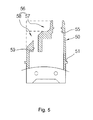
- FIG. 5 is a schematic sectional view of a cell block extracted from the handheld salinity analyzer
- FIG. 6 is a schematic front sectional view illustrating the handheld salinity analyzer in use under the condition that a body cover is taken off and then is connected to an end of a body provided with an ON/OFF switch;
- FIG. 7 is a schematic perspective view illustrating the inside of the body cover.
- FIG. 2 is a schematic perspective view of a handheld salinity analyzer in accordance with the present invention
- FIG. 3 is a schematic side sectional view of the handheld salinity analyzer
- FIG. 4 is a schematic front sectional view of the handheld salinity analyzer
- FIG. 5 is a schematic sectional view of a cell block extracted from the handheld salinity analyzer
- FIG. 6 is a schematic front sectional view illustrating the handheld salinity analyzer in use under the condition that a body cover is taken off and then is connected to an end of a body provided with an ON/OFF switch
- FIG. 7 is a schematic perspective view illustrating the inside of the body cover.
- the handheld salinity analyzer in accordance with the present invention includes a body 10 , a clip 20 , a circuit board 30 , a battery 40 , a cell block 50 , a salinity sensor 60 , a temperature sensor 70 , an ON/OFF switch 80 , a light emitting lamp 90 , and a body cover 100 .
- the body 10 is formed in a hollow shape, and is provided with a pressing part 11 on the front surface thereof, and a through hole 12 formed at one side of the pressing part 11 .
- a clip fixing part 13 is formed on the rear surface of the body 10 , and a battery cover 14 is detachably provided at one side of the clip fixing part 13 .
- Attachable and detachable grooves 15 are formed on the outer surface of one end of the body 10 such that attachable and detachable protrusions 101 are attached to and detached from the attachable and detachable grooves 15 , and attachable and detachable protrusions 16 are protruded from the inner surface of the other end of the body 10 such that the attachable and detachable protrusions 16 are attached to and detached from first attachable and detachable grooves 52 of the cell block 50 , which will be described later.
- the clip 20 is provided with one end connected to the clip fixing part 13 of the body 10 and the other end such as clothes or a bag.
- a user may conveniently carry the handheld salinity analyzer of the present invention on clothes or a pocket of a bag just like a writing instrument.
- the circuit board 30 is installed within the body 10 , and is provided with a button 31 formed thereon so as to be opposite to the pressing part 11 and a display part 32 connected thereto so as to be opposite to the through hole 12 of the body 10 . Therefore, when the user presses the pressing part 11 of the body 10 , the button 31 is pressed and data is input to the circuit board 30 . Further, a measured salinity value is displayed through the display part 32 such that the user may read the measured salinity value.
- the battery 40 is installed in the body 10 at a position within the battery cover 14 , and is connected to the circuit board 30 so as to supply power to the circuit board 30 .
- the cell block 50 is provided with one end inserted into one end of the body 10 so as to be opposite to one end of the circuit board 30 , and is provided with the other end exposed to the outside of the body 10 .
- a projecting part 54 and a depressed part 56 are formed on the other end of the cell block 50 .
- a salinity sensor hole 55 connected to the circuit board 30 is formed through the projecting part 54
- a temperature sensor hole 59 connected to the circuit board 30 is formed through the depressed part 56 .
- the first attachable and detachable grooves 52 connected to the attachable and detachable protrusions 16 of the body 10 and second attachable and detachable grooves 53 connected to the attachable and detachable protrusions 101 of the body cover 100 are formed on the outer surface of the cell block 50 .
- a flange 51 which is supported by the end of the body 10 to restrict the insertion of the cell block 50 when the cell block 50 is inserted into the end of the body 10 , is formed around the outer surface of the cell block 50 between the first attachable and detachable grooves 52 and the second attachable and detachable grooves 53 .
- the depressed part 56 includes a first depression part 57 and a second depression part 58 .
- a pressing end 104 of an operating piece 103 is located in the first depression part 57 , when the body cover 100 is connected to the other end of the body 10 provided with the cell block 50 .
- One end of the temperature sensor 70 protruding to the outside, is located in the second depression part 58 , and the second depression part 58 is inclined at one side of the first depression part 57 so as to prevent interference between the end of the temperature sensor 70 and the pressing end 104 , when the pressing end 104 of the operating piece 103 is located in the first depression part 57 .
- the salinity sensor 60 is inserted into the salinity sensor hole 55 of the cell block 50 , and one end of the salinity sensor 60 is connected to the circuit board 30 and the other end of the salinity sensor 60 contacts a food sample to measure salinity of the food sample.
- the temperature sensor 70 is inserted into the temperature sensor hole 59 of the cell block 50 , and one end of the temperature sensor 70 is connected to the circuit board 30 and the other end of the temperature sensor 70 is exposed to the outside of the second depression part 58 and thus directly contacts the food sample.
- the ON/OFF switch 80 is installed on the end of the body 10 in opposite to the cell block 50 and is connected to the circuit board 30 and the battery 40 , and one end of the ON/OFF switch 80 is protruded to the outside of the end of the body 10 .
- the ON/OFF switch 80 When external force is applied to the end of the ON/OFF switch 80 , power of the battery 40 is supplied to the circuit board 30 and thus the salinity analyzer is operated, and when the external force is removed from the ON/OFF switch 80 , the ON/OFF switch 80 is turned off and thus power supplied to the circuit board 30 is cut off.
- the light emitting lamp 90 is installed at one side of the ON/OFF switch 80 , and is connected to the circuit board 30 .
- the light emitting lamp 90 emits light of different colors, if the measured salinity of the food sample is less than a set value and if the measured salinity of the food sample is more than the set value.
- the light emitting lamp 90 will be described in more detail.
- a blue LED (not shown) and a red LED (not shown) are installed in the light emitting lamp 90 , and are connected to the circuit board 30 .
- a reference salinity value is set in the circuit board 30 of the handheld salinity analyzer. Further, the circuit board 30 is programmed such that salinity of a food sample is measured, and when the measured salinity is less than the set value, the blue LED is turned on, and when the measured salinity is more than the set value, the red LED is turned on.
- the light emitting lamp 90 when the measured salinity of the food sample is less than the set value, the light emitting lamp 90 emits blue light, and when the measured salinity of the food sample is more than the set value, the light emitting lamp 90 emits red light.
- the body cover 100 is connected to the end of the body 10 provided with the ON/OFF switch 80 or to the cell block 50 .
- the body cover 100 is provided with the operating piece 103 formed therein so as to apply force to the ON/OFF switch 80 , when the body cover 100 is connected to the end of the body 10 provided with the ON/OFF switch 80 , and to remove the force from the ON/OFF switch 80 , when the body cover 100 is separated from the end of the body 10 .
- Such a body cover 100 is made of a transparent material, and a plurality of diffused reflection protrusions 102 to diffuse light emitted from the light emitting lamp 90 when the light emitting lamp 90 is turned on is formed on the inner surface of the body cover 100 . Further, the attachable and detachable protrusions 101 , which are connected to the attachable and detachable grooves 15 of the body 10 or the second attachable and detachable grooves 53 of the cell block 50 , protrude from the inner surface of an entrance of the body cover 100 .
- the operating piece 103 of the body cover 100 is fixed to the body cover 100 such that the operating piece 103 occupies a space corresponding to half of the inner space of the body cover 100 so as to secure an entrance space 105 , which the projecting part 54 of the cell block 50 and the salinity sensor 60 enter.
- the pressing end 104 of the operating piece 103 presses the ON/OFF switch 80 to operate the ON/OFF switch 80 , and when the body cover 100 is separated from the end of the body 10 , the pressing of the ON/OFF switch 80 by the pressing end 104 of the operating piece 103 is released. Further, when the body cover 100 is connected to the other end of the body 10 , at which the sensors are located, the pressing end 104 of the operating piece 103 is located in the first depression part 57 of the cell block 50 .
- the above-described handheld salinity analyzer of the present invention is carried by a user such that the clip 20 is inserted into a pocket of clothes or a bag under the condition that the body cover 100 is connected to the cell block 50 .
- the attachable and detachable protrusions 16 of the body cover 100 are connected to the second attachable and detachable grooves of the cell block 50
- the pressing end 104 of the operating piece 103 is located in the first depression part 57 of the cell block 50 .
- the end of the temperature sensor 70 is located in the second depression part 58
- the projecting part 54 of the cell block 50 and the salinity sensor 60 are located in the entrance space 105 of the body cover 100 .
- the body cover 100 is separated from the cell block 50 , and then is inserted into the end of the body 10 provided with the ON/OFF switch 80 .
- the attachable and detachable protrusions 101 of the body cover 100 are connected to the attachable and detachable grooves 15 of the body 10 .
- the pressing end 104 of the operating piece 103 presses the ON/OFF switch 80 , as shown in FIG. 7 , and thereby the ON/OFF switch 80 is turned on and the handheld salinity analyzer is operated.
- the handheld salinity analyzer is operated, the salinity sensor 60 and the temperature sensor 70 are dipped in a food sample so as to measure salinity of the food sample.
- the salinity sensor 60 , the temperature sensor 70 , and the cell block 50 which were dipped in the food sample, are washed, the body cover 100 is separated from the end of the body 10 provided with the ON/OFF switch 80 , and the separated body cover 100 is connected to the other end of the body 100 provided with the cell block 50 .
- the pressing of the ON/OFF switch 80 by the pressing end 104 of the operating piece 103 is released, and the ON/OFF switch 80 is turned off, thereby cutting-off power of the battery 40 .
- the handheld salinity analyzer of the present invention has advantages, as follows.
- one end of the clip 20 is fixed to the rear surface of the body 10 .
- the user may conveniently and safely carry the handheld salinity analyzer of the present invention just like a pen, and easily use the handheld salinity analyzer at any place.
- the pressing end 104 of the operating piece 103 presses the ON/OFF switch 80 , and thus the handheld salinity analyzer is operated.
- the pressing of the ON/OFF switch 80 by the pressing end 104 of the operating piece 103 is released, and the ON/OFF switch 80 is turned off. Therefore, since, when the body cover 100 is connected to the cell block 50 so as to keep the salinity sensor after use, the ON/OFF switch 80 is automatically turned off, it is possible to solve the conventional problem, i.e., unnecessary consumption of power of the battery 40 as the salinity sensor is kept under the condition that the ON/OFF switch 80 is not turned off.
- the end of the temperature sensor 70 is protruded toward the second depression part 58 . Therefore, when the end of the cell block 50 is dipped in a food sample, the end of the temperature sensor 70 exposed to the outside directly contacts the sample, thereby rapidly and correctly measuring a temperature of the sample.
- the light emitting lamp 90 when the measured salinity of the food sample is less than a set value, the light emitting lamp 90 emits blue light through the blue LED, and when the measured salinity of the food sample is more than the set value, the light emitting lamp 90 emits red light through the red LED. Therefore, a user can easily judge whether or not the salinity of the food sample is less than or more than the proper set value without the confirmation of numbers displayed on the display part 32 .
- the body cover 100 is made of a transparent material, and a plurality of diffused reflection protrusions 102 to diffuse light emitted from the light emitting lamp 90 when the light emitting lamp 90 is turned on is formed on the inner surface of the body cover 100 . Therefore, the light emitted from the light emitting lamp is diffused due to collision with the plurality of diffused reflection protrusions 102 , and thus is diffused throughout the end of the body cover 100 , thereby improving the design of the handheld salinity analyzer in use and allowing the user to correctly confirm the light emitted from the light emitting lamp 90 .
Landscapes
- Health & Medical Sciences (AREA)
- Life Sciences & Earth Sciences (AREA)
- Chemical & Material Sciences (AREA)
- Engineering & Computer Science (AREA)
- Food Science & Technology (AREA)
- Physics & Mathematics (AREA)
- Medicinal Chemistry (AREA)
- Analytical Chemistry (AREA)
- Biochemistry (AREA)
- General Health & Medical Sciences (AREA)
- General Physics & Mathematics (AREA)
- Immunology (AREA)
- Pathology (AREA)
- Investigating Or Analysing Materials By Optical Means (AREA)
- Investigating Or Analyzing Materials By The Use Of Electric Means (AREA)
Abstract
Description
Claims (5)
Applications Claiming Priority (3)
| Application Number | Priority Date | Filing Date | Title |
|---|---|---|---|
| KR10-2009-0066472 | 2009-07-21 | ||
| KR10-2009-66472 | 2009-07-21 | ||
| KR1020090066472A KR101047964B1 (en) | 2009-07-21 | 2009-07-21 | Pocket Salty Sensor |
Publications (2)
| Publication Number | Publication Date |
|---|---|
| US20110018725A1 US20110018725A1 (en) | 2011-01-27 |
| US8330604B2 true US8330604B2 (en) | 2012-12-11 |
Family
ID=43496814
Family Applications (1)
| Application Number | Title | Priority Date | Filing Date |
|---|---|---|---|
| US12/725,312 Active - Reinstated 2031-06-09 US8330604B2 (en) | 2009-07-21 | 2010-03-16 | Handheld salinity analyzer |
Country Status (2)
| Country | Link |
|---|---|
| US (1) | US8330604B2 (en) |
| KR (1) | KR101047964B1 (en) |
Families Citing this family (10)
| Publication number | Priority date | Publication date | Assignee | Title |
|---|---|---|---|---|
| JP5612141B2 (en) * | 2012-02-10 | 2014-10-22 | 孫 允縞Yun−Ho SON | Salinity meter with built-in impact switch |
| WO2013130798A1 (en) * | 2012-02-29 | 2013-09-06 | Nomiku Inc. | Apparatus and system for low-temperature cooking |
| US9826855B2 (en) * | 2013-12-03 | 2017-11-28 | Anova Applied Electronics, Inc. | Circulator cooker with alarm system |
| USRE49267E1 (en) * | 2013-02-14 | 2022-11-01 | Anova Applied Electronics, Inc. | Circulator cooker with alarm system |
| KR101600368B1 (en) | 2014-05-22 | 2016-03-07 | 길주형 | Selective Ion Meter For Test Strip |
| US20160192801A1 (en) * | 2015-01-02 | 2016-07-07 | Jeff Wu | Circulator cooker |
| KR102488774B1 (en) * | 2016-03-28 | 2023-01-13 | 엘지전자 주식회사 | Hanger-type cooking information provision device |
| US10952412B2 (en) * | 2017-07-14 | 2021-03-23 | King Abdullah University Of Science And Technology | Compliant, lightweight, non-invasive, standalone tagging system for marine exploration and method |
| CN109115837B (en) * | 2018-08-28 | 2024-04-30 | 东莞市盛山电子科技有限公司 | Intelligent correction anti-interference high-precision salinity detector |
| USD922700S1 (en) | 2018-12-28 | 2021-06-15 | Samsung Electronics Co., Ltd. | Dryer |
Citations (4)
| Publication number | Priority date | Publication date | Assignee | Title |
|---|---|---|---|---|
| US4331923A (en) * | 1979-08-06 | 1982-05-25 | Akers Jr Raymond F | Salts monitoring device |
| US4918391A (en) * | 1988-03-17 | 1990-04-17 | Enseal, Inc. | Sodium content monitor having a unitary housing |
| US20060139037A1 (en) * | 2004-12-28 | 2006-06-29 | Hughes William C | Soil probe device and method of making same |
| US20070048224A1 (en) * | 2004-12-20 | 2007-03-01 | Howell Thomas A | Method and apparatus to sense hydration level of a person |
Family Cites Families (3)
| Publication number | Priority date | Publication date | Assignee | Title |
|---|---|---|---|---|
| KR20060014154A (en) * | 2004-08-10 | 2006-02-15 | (주)바이오텔 | Portable salinity measurement and alarm device using salinity meter and its method |
| KR100912714B1 (en) | 2007-07-25 | 2009-08-19 | 대윤계기산업 주식회사 | Salinity meter |
| KR101030302B1 (en) * | 2008-10-16 | 2011-04-19 | 대윤계기산업 주식회사 | Salinity meter |
-
2009
- 2009-07-21 KR KR1020090066472A patent/KR101047964B1/en active Active
-
2010
- 2010-03-16 US US12/725,312 patent/US8330604B2/en active Active - Reinstated
Patent Citations (5)
| Publication number | Priority date | Publication date | Assignee | Title |
|---|---|---|---|---|
| US4331923A (en) * | 1979-08-06 | 1982-05-25 | Akers Jr Raymond F | Salts monitoring device |
| US4918391A (en) * | 1988-03-17 | 1990-04-17 | Enseal, Inc. | Sodium content monitor having a unitary housing |
| US20070048224A1 (en) * | 2004-12-20 | 2007-03-01 | Howell Thomas A | Method and apparatus to sense hydration level of a person |
| US20060139037A1 (en) * | 2004-12-28 | 2006-06-29 | Hughes William C | Soil probe device and method of making same |
| US7183779B2 (en) * | 2004-12-28 | 2007-02-27 | Spectrum Technologies, Inc. | Soil probe device and method of making same |
Also Published As
| Publication number | Publication date |
|---|---|
| US20110018725A1 (en) | 2011-01-27 |
| KR20110008913A (en) | 2011-01-27 |
| KR101047964B1 (en) | 2011-07-12 |
Similar Documents
| Publication | Publication Date | Title |
|---|---|---|
| US8330604B2 (en) | Handheld salinity analyzer | |
| US11073482B2 (en) | Multi-functional precious stone testing apparatus and method thereof | |
| US10203288B2 (en) | Multi-functional precious stone testing apparatus and method thereof | |
| US8947111B2 (en) | Multi-functional precious stone testing apparatus and method thereof | |
| US9395350B2 (en) | Gem tester | |
| US8749253B2 (en) | Gem tester | |
| WO2016082620A1 (en) | Article storage device | |
| US11243170B2 (en) | Multi-functional precious stone testing apparatus and method thereof | |
| US20050083991A1 (en) | Probe cover storage system for ear thermometer | |
| US20050085733A1 (en) | Ear thermometer illumination system | |
| CN104700195A (en) | Article storage information display method and device | |
| JP2008079676A (en) | Blood flow sensor | |
| JP4955437B2 (en) | Biochemical measuring instrument stand that can display the status of the biochemical measuring instrument | |
| CN101458120A (en) | Hand-held optical power gauge | |
| CN211014670U (en) | Wall tester | |
| CN216669009U (en) | Infrared thermometer | |
| JP6184818B2 (en) | Component measuring device | |
| CN210720551U (en) | Test pencil | |
| CN215114930U (en) | Temperature-measuring and throat-detecting integrated device | |
| TWM570422U (en) | Temperature warning tableware structure | |
| CN102357032A (en) | Electric thermometer | |
| CN209026563U (en) | working lamp | |
| CN101354395A (en) | Females physiologic status electronic detector | |
| CN118377213A (en) | Intelligent watch for detecting female health | |
| CN102327112A (en) | Convenient thermometer |
Legal Events
| Date | Code | Title | Description |
|---|---|---|---|
| AS | Assignment |
Owner name: DAE YOON SCALE INDUSTRIAL CO., LTD., KOREA, REPUBL Free format text: ASSIGNMENT OF ASSIGNORS INTEREST;ASSIGNORS:YANG, GIL MO;CHO, EUN GI;LEE, KANG JIN;AND OTHERS;SIGNING DATES FROM 20100223 TO 20100224;REEL/FRAME:024089/0533 Owner name: REPUBLIC OF KOREA (MANAGEMENT: RURAL DEVELOPMENT A Free format text: ASSIGNMENT OF ASSIGNORS INTEREST;ASSIGNORS:YANG, GIL MO;CHO, EUN GI;LEE, KANG JIN;AND OTHERS;SIGNING DATES FROM 20100223 TO 20100224;REEL/FRAME:024089/0533 |
|
| AS | Assignment |
Owner name: REPUBLIC OF KOREA (MANAGEMENT: RURAL DEVELOPMENT A Free format text: ASSIGNMENT OF ASSIGNORS INTEREST;ASSIGNOR:DAE YOON SCALE INDUSTRIAL CO., LTD.;REEL/FRAME:029566/0446 Effective date: 20121221 |
|
| REMI | Maintenance fee reminder mailed | ||
| LAPS | Lapse for failure to pay maintenance fees | ||
| FP | Lapsed due to failure to pay maintenance fee |
Effective date: 20161211 |
|
| PRDP | Patent reinstated due to the acceptance of a late maintenance fee |
Effective date: 20170921 |
|
| FEPP | Fee payment procedure |
Free format text: SURCHARGE, PETITION TO ACCEPT PYMT AFTER EXP, UNINTENTIONAL. (ORIGINAL EVENT CODE: M2558); ENTITY STATUS OF PATENT OWNER: SMALL ENTITY Free format text: PETITION RELATED TO MAINTENANCE FEES GRANTED (ORIGINAL EVENT CODE: PMFG) Free format text: PETITION RELATED TO MAINTENANCE FEES FILED (ORIGINAL EVENT CODE: PMFP) |
|
| MAFP | Maintenance fee payment |
Free format text: PAYMENT OF MAINTENANCE FEE, 4TH YR, SMALL ENTITY (ORIGINAL EVENT CODE: M2551) Year of fee payment: 4 |
|
| STCF | Information on status: patent grant |
Free format text: PATENTED CASE |
|
| MAFP | Maintenance fee payment |
Free format text: PAYMENT OF MAINTENANCE FEE, 8TH YR, SMALL ENTITY (ORIGINAL EVENT CODE: M2552); ENTITY STATUS OF PATENT OWNER: SMALL ENTITY Year of fee payment: 8 |
|
| MAFP | Maintenance fee payment |
Free format text: PAYMENT OF MAINTENANCE FEE, 12TH YR, SMALL ENTITY (ORIGINAL EVENT CODE: M2553); ENTITY STATUS OF PATENT OWNER: SMALL ENTITY Year of fee payment: 12 |