US8328671B2 - Randomized chain sprocket and method for making a sprocket - Google Patents
Randomized chain sprocket and method for making a sprocket Download PDFInfo
- Publication number
- US8328671B2 US8328671B2 US12/700,906 US70090610A US8328671B2 US 8328671 B2 US8328671 B2 US 8328671B2 US 70090610 A US70090610 A US 70090610A US 8328671 B2 US8328671 B2 US 8328671B2
- Authority
- US
- United States
- Prior art keywords
- tooth gap
- sprocket
- tooth
- uniform
- random
- Prior art date
- Legal status (The legal status is an assumption and is not a legal conclusion. Google has not performed a legal analysis and makes no representation as to the accuracy of the status listed.)
- Expired - Fee Related, expires
Links
Images


Classifications
-
- F—MECHANICAL ENGINEERING; LIGHTING; HEATING; WEAPONS; BLASTING
- F16—ENGINEERING ELEMENTS AND UNITS; GENERAL MEASURES FOR PRODUCING AND MAINTAINING EFFECTIVE FUNCTIONING OF MACHINES OR INSTALLATIONS; THERMAL INSULATION IN GENERAL
- F16H—GEARING
- F16H55/00—Elements with teeth or friction surfaces for conveying motion; Worms, pulleys or sheaves for gearing mechanisms
- F16H55/02—Toothed members; Worms
- F16H55/30—Chain-wheels
-
- F—MECHANICAL ENGINEERING; LIGHTING; HEATING; WEAPONS; BLASTING
- F16—ENGINEERING ELEMENTS AND UNITS; GENERAL MEASURES FOR PRODUCING AND MAINTAINING EFFECTIVE FUNCTIONING OF MACHINES OR INSTALLATIONS; THERMAL INSULATION IN GENERAL
- F16H—GEARING
- F16H55/00—Elements with teeth or friction surfaces for conveying motion; Worms, pulleys or sheaves for gearing mechanisms
- F16H55/02—Toothed members; Worms
- F16H55/14—Construction providing resilience or vibration-damping
-
- F—MECHANICAL ENGINEERING; LIGHTING; HEATING; WEAPONS; BLASTING
- F16—ENGINEERING ELEMENTS AND UNITS; GENERAL MEASURES FOR PRODUCING AND MAINTAINING EFFECTIVE FUNCTIONING OF MACHINES OR INSTALLATIONS; THERMAL INSULATION IN GENERAL
- F16H—GEARING
- F16H7/00—Gearings for conveying rotary motion by endless flexible members
- F16H7/06—Gearings for conveying rotary motion by endless flexible members with chains
-
- F—MECHANICAL ENGINEERING; LIGHTING; HEATING; WEAPONS; BLASTING
- F16—ENGINEERING ELEMENTS AND UNITS; GENERAL MEASURES FOR PRODUCING AND MAINTAINING EFFECTIVE FUNCTIONING OF MACHINES OR INSTALLATIONS; THERMAL INSULATION IN GENERAL
- F16H—GEARING
- F16H55/00—Elements with teeth or friction surfaces for conveying motion; Worms, pulleys or sheaves for gearing mechanisms
- F16H55/02—Toothed members; Worms
- F16H55/30—Chain-wheels
- F16H2055/306—Chain-wheels with means providing resilience or vibration damping in chain sprocket wheels
-
- Y—GENERAL TAGGING OF NEW TECHNOLOGICAL DEVELOPMENTS; GENERAL TAGGING OF CROSS-SECTIONAL TECHNOLOGIES SPANNING OVER SEVERAL SECTIONS OF THE IPC; TECHNICAL SUBJECTS COVERED BY FORMER USPC CROSS-REFERENCE ART COLLECTIONS [XRACs] AND DIGESTS
- Y10—TECHNICAL SUBJECTS COVERED BY FORMER USPC
- Y10T—TECHNICAL SUBJECTS COVERED BY FORMER US CLASSIFICATION
- Y10T29/00—Metal working
- Y10T29/49—Method of mechanical manufacture
- Y10T29/49462—Gear making
- Y10T29/49467—Gear shaping
Definitions
- the invention relates to chain and sprocket drives, and more particularly, to a sprocket having reduced noise and vibrations.
- Timing chain drive systems which comprise a chain and sprockets.
- Example chain configurations known in the art include; inverted teeth (IT) chains, bush chains and roller chains. Due to the impact of the chain on the sprocket during meshing, the chain generates vibration and noise. Due to the uniform distribution of the sprocket teeth along the sprocket perimeter, vibration and noises occur at fundamental meshing frequency and this frequency is in positive integer multiples.
- the invention provides a chain and sprocket drive system using a chain with a constant pitch and a sprocket wherein some of the adjacent tooth gaps have different tooth gap radial locations. This provides a construction with reduced noise and vibration.
- a roller chain by varying the root radial locations of some of the adjacent roots, the time interval between contact of the roller and the sprocket is varied and hence the uniform pattern is broken.
- a set of four consecutive roots is employed where the middle two roots have different root radial locations than the other two roots.
- the four consecutive roots have at least two different link angles.
- One method for making the sprocket comprises forming a circle defined by the pitch radius of the sprocket; forming a polygon having sides which are equal to the chain pitch inside the circle; and then changing the shape of the polygon while maintaining the length of the sides of the polygon in order to arrive at different link angles.
- a preferred method for making the sprocket comprises forming a trapezoid with a base having a length equal to the distance between a center of a pin in a first tooth gap and a center of a pin in a fourth tooth gap of a set of four consecutive tooth gaps, the top and legs of the trapezoid having a length equal to the chain pitch; changing the shape of the trapezoid while maintaining the length of the sides of the trapezoid; and determining a tooth gap radial location for each tooth gap of the set of four consecutive tooth gaps based on assigning each vertex of the changed trapezoid as the center of a pin positioned in one of the tooth gaps of the set of four consecutive tooth gaps.
- the chain and sprocket drive of the invention include: a chain having pins interconnected by links, each of the pins having a central axis and a chain pitch defined as a distance between the central axis of adjacent pins, the chain pitch being constant.
- the chain configuration includes, but is not limited to, roller chains, bush chains and inverted teeth (IT) chains.
- a sprocket having teeth and tooth gaps is spaced about the periphery of the sprocket, one of each of the tooth gaps is located between adjacent teeth for receiving one of the rollers bushes or link teeth.
- Each of the tooth gaps has a tooth gap radial location defined as a distance between the center of the sprocket and a point located to the chain pin center of a fully seated link in a radial direction.
- At least one set of four consecutive tooth gaps is defined as a first tooth gap, a second tooth gap, a third tooth gap and a fourth tooth gap,
- the first tooth gap and the fourth tooth gap have the same tooth gap radial location
- the second tooth gap and the tooth gap root have a different tooth gap radial location from each other and from the first and the fourth root.
- the set of four consecutive tooth gaps has two different link angles, a first link angle defined by an angle between a first link center line and a second link center line and the second link angle defined as an angle between the second link center line and a third link center line.
- the first link center line is defined by the central axis of a pin in the first tooth gap and the central axis of a pin in the second tooth gap.
- the second link center line is defined by the central axis of a pin in the second tooth gap and the central axis of a pin in the third tooth gap.
- the third link center line is defined by the central axis of a pin in the third tooth gap and the central axis of a pinin the fourth tooth gap.
- One method of the invention for making a sprocket with reduced noise and vibration for a chain and sprocket drive broadly includes: selecting a uniform chain having pins interconnected by links, each of the pins having a central axis and a chain pitch defined as a distance between the central axis of adjacent pins, the chain pitch being constant. Next, a uniform sprocket is selected which has a plurality of uniform teeth and uniform tooth gaps spaced about the periphery of the sprocket, one of each of the uniform tooth gaps is located between adjacent uniform teeth.
- Each of the uniform tooth gaps has a tooth gap radial location defined as a distance between the center of the uniform sprocket and a point located at the chain pin center of a fully seated link in a radial direction, each uniform tooth gap having the same tooth gap radial location.
- a pitch circle having a radius defined as a distance between the center of the uniform sprocket and the central axis of a pin is drawn in one of the uniform tooth gaps.
- a uniform sprocket polygon is positioned inside the pitch circle, with every vertex of the polygon touching the pitch circle and each side of the polygon being equal to the chain pitch.
- a first random sprocket polygon is formed by altering the vertices between the sides of the uniform polygon while maintaining the length of each side.
- a first vertex angle is determined in a vertex of the first random polygon and a first supplementary angle of the first vertex angle.
- a second random sprocket polygon is formed that is different than the first random polygon, by altering the vertices between the sides of the uniform polygon while maintaining the length of each side.
- a second vertex angle is determined in a vertex of the second random polygon and a second supplementary angle of the second vertex angle.
- a random sprocket is made having random teeth and random tooth gaps spaced about the periphery of the random sprocket.
- Each of the random tooth gaps is located between adjacent random teeth.
- Each of the random tooth gaps has a tooth gap radial location defined as a distance between the center of the random sprocket and a point located at the chain pin center of a fully seated link in a radial direction.
- At least one set of four consecutive random tooth gaps is defined as a first tooth gap, a second tooth gap, a third tooth gap and a fourth tooth gap.
- the first tooth gap and the fourth tooth gap have the same tooth gap radial location, and the second tooth gap and the third tooth gap have a different tooth gap radial location from each other and from the first and the fourth tooth gap.
- the set of four consecutive random tooth gaps has two different link angles.
- a first link angle is defined by an angle between a first link center line and a second link center line and the second link angle is defined as an angle between the second link center line and a third link center line.
- the first link center line is defined by the central axis of a pin in the first tooth gap and the central axis of a pin in the second tooth gap.
- the second link center line is defined by the central axis of a pin in the second tooth gap and the central axis of a pin in the third tooth gap.
- the third link center line is defined by the central axis of a pin in the third tooth gap and the central axis of a pin in the fourth tooth gap.
- One of the two different link angles is equal to the first supplementary angle and the second of the two different link angles is equal to the second supplementary angle.
- Another method for making a sprocket includes: selecting a uniform chain having pins interconnected by links, each of the pins having a central axis and a chain pitch defined as a distance between the central axis of adjacent pins, the chain pitch being constant.
- a uniform sprocket is selected having a plurality of uniform teeth and uniform tooth gaps spaced about the periphery of the sprocket. One of each of the uniform tooth gaps is located between adjacent uniform teeth.
- Each of the uniform tooth gaps has a tooth gap radial location defined as a distance between the center of the uniform sprocket and a point located at the chain pin center of a fully seated link in a radial direction, each uniform tooth gap having the same tooth gap radial location.
- a uniform trapezoid is formed with a base having a length equal to the distance between a center of a pin in a first tooth gap and the center of a pin in a fourth uniform tooth gap of a set of four consecutive uniform tooth gaps of the uniform sprocket.
- the top and legs of the uniform trapezoid equal in length to the chain pitch.
- a quadrilateral is formed by moving vertices of the uniform trapezoid while maintaining the length of each side.
- a random sprocket is made having at least one set of four consecutive random tooth gaps by assigning each vertex of the quadrilateral to a center of one of four consecutive pins in the uniform chain and positioning the four consecutive pins in the four consecutive random tooth gaps.
- the two vertices of the trapezoid that form the ends of the base are not moved while the two vertices that form the ends of top of the trapezoid are moved.
- the sprocket of the present invention has a set of four consecutive random tooth gaps with a first tooth gap radial location and a fourth tooth gap radial location measuring the same, the second tooth gap radial location is less than the first tooth gap radial location and the third tooth gap radial location is greater than the first tooth gap radial location.
- the first and the fourth tooth gap radial locations are the same while the second tooth gap radial location is greater than the first tooth gap radial location and the third root radial location is less than the first root radial location.
- the sprocket of the present invention can also have more than one set of the four consecutive random tooth gaps.
- FIG. 1 illustrates the chain and sprocket drive assembly, including an example roller chain known in the art
- FIG. 2 illustrates in more detail the sprocket of the present invention for roller and bush chains
- FIG. 2 ′ illustrates in more detail the sprocket of the present invention for IT chains
- FIG. 3 illustrates the uniform and random polygon for designing the sprocket of the invention
- FIG. 4 illustrates the preferred method for making the sprocket using a trapezoid
- FIG. 5 illustrates a sprocket with a plurality of non-uniform tooth gap patterns for roller and bush chains
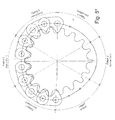
- FIG. 5 ′ illustrates a sprocket with a plurality of non-uniform tooth gap patterns for IT chains.
- FIG. 1 illustrates a roller chain drive system 10 which is rotated in the direction of arrow 11 .
- Roller chain drive system 10 has a drive sprocket 12 , a driven sprocket 14 , and roller chain 16 which interconnects the two sprockets.
- Each sprocket 12 and 14 has sprocket teeth 18 positioned around the periphery of the sprocket. Between each of the sprocket teeth 18 is a tooth gap 20 . Each tooth gap 20 has a tooth gap radial location 22 which is measured from center 24 of the sprocket to point 26 on the tooth gap closest to center 24 . This point 26 can conventionally be defined as the bottom of tooth gap 20 . Pitch radius 28 is defined as the distance between center 24 of the sprocket and center 38 of each roller 36 of chain 16 positioned in the tooth gap 20 .
- Chain 16 has inner links 30 and outer links 32 that interconnect rollers 36 .
- the links are interconnected by bushings or pins 34 .
- Rollers 36 are positioned between the links and are freely rotatable. Each roller 36 has a center of rotation 38 about which it rotates.
- Chain pitch 40 is a measurement between center 38 of adjacent rollers 36 .
- chain 16 has uniform or constant chain pitch. In other words, the distance between center 38 of adjacent rollers 36 is constant on chain 16 .
- FIG. 2 illustrates the four consecutive tooth gaps having different tooth gap radial locations and different link angles.
- first tooth gap 20 A is adjacent second tooth gap 20 B, which in turn is adjacent to third tooth gap 20 C which in turn is adjacent to fourth tooth gap 20 D.
- Each tooth gap 20 A, 20 B, 20 C, and 20 D have a respective tooth gap radial location labeled 22 A, 22 B, 22 C, and 22 D.
- Positioned in each tooth gap is a respective roller labeled 36 A, 36 B, 36 C, and 36 D.
- Each roller has a respective center labeled 38 A, 38 B, 38 C, and 38 D.
- first center line 50 is defined by center 38 A of roller 36 A and center 38 B of roller 36 B.
- Second center line 52 is defined by center 38 B of roller 36 B and center 38 C of roller 36 C.
- Third center line 54 is defined by center 38 C of roller 36 C and center 38 D of roller 36 D.
- link angle 56 is different than link angle 58 .
- tooth gap radial location 22 A and tooth gap radial location 22 D are the same while tooth gap radial location 22 B is less than tooth gap radial location 22 A and 22 D. Tooth gap radial location 22 C is greater than tooth gap radial location 22 A, 22 B, and 22 D.
- a sprocket made in accordance with FIG. 2 has rollers 36 hitting respective tooth gaps 20 at different time intervals thereby breaking the noise and vibrations.
- FIG. 2 ′ shows the sprocket for an IT chain.
- the pins 39 replace the rollers 36 of FIG. 2 . Otherwise, the basic concept of FIG. 2 applies equally to FIG. 2 ′.
- FIG. 3 illustrates a method for determining the different link angles to be used for the set of four consecutive tooth gaps.
- Pitch circle 60 has a radius 28 which is equal to the pitch radius of a desired sprocket.
- a uniform sprocket polygon 62 having each side equal in length to chain pitch 40 .
- Uniform sprocket polygon 62 has a vertex angle 66 and a supplementary angle 68 .
- Supplementary angle 68 equals the link angle and the link angle of this uniform sprocket has uniform tooth gap radial locations 22 .
- the uniform sprocket polygon is shifted to provide random sprocket polygon 64 .
- Random sprocket polygon 64 has the same side walls as uniform sprocket 62 , i.e. each side of random sprocket 64 has a length equal to chain pitch 40 .
- supplementary random angle 72 is determined from vertex angle 70 of random polygon 64 .
- the sprocket in altering the polygon to form random polygon 64 , the sprocket must be properly designed so that rollers fully seat in every root and that edges have equal lengths and the length being equal to the chain pitch so as to use a chain with constant chain pitch. By ensuring that this is met, proper chain meshing will be achieved during full sprocket rotation.
- FIG. 4 illustrates the preferred method for making a random sprocket.
- FIG. 4 illustrates a portion of a sprocket with teeth 74 and four consecutive roots 76 A, 76 B, 76 C, and 76 D.
- the center of rotation 78 A 0 0 , 78 A 0 1 , 78 A 0 2 , and 78 A 0 3 is shown for each roller.
- a uniform trapezoid has the vertices 78 A 0 0 , 78 A 0 1 , 78 A 0 2 , 78 A 0 3 with base 78 A 0 0 - 78 A 0 3 , top 78 A 0 1 - 78 A 0 2 , and sides or legs 78 A 0 0 - 78 A 0 1 and 78 A 0 2 - 78 A 0 3 .
- Base 78 A 0 0 - 78 A 0 3 is parallel to top 78 A 0 1 - 78 A 0 2 .
- the vertex 78 A 0 1 is moved to 78 A 1 and the vertex 78 A 0 2 is moved to 78 A 2 .
- Vertices 78 A 0 0 and 78 A 0 3 remain fixed.
- a quadrilateral is formed and labeled 78 A 0 , 78 A 1 , 78 A 2 , and 78 A 3 .
- the vertices of quadrilateral 78 A 0 , 78 A 1 , 78 A 2 , and 78 A 3 define the new center of rotation for rollers in tooth gaps 76 A, 76 B, 76 C, and 76 D. Since the rollers have the same diameters, the tooth gap radial location for tooth gaps 76 B and 76 C change to accommodate the new centers 78 A 1 and 78 A 2 .
- FIG. 5 illustrates a non-uniform sprocket 80 with rollers 82 , a plurality of non-uniform patterns, labeled Patterns 1 , 2 , and 3 , repeated several times at different locations around the periphery of sprocket 80 .
- Each pattern is different with the non-uniform tooth gap radial locations arrived at using the methods of the invention.
- the x's mark roller centers which are not uniform, away from pitch circle 84 .
- the centers marked with a solid circle are rollers 82 with centers of rotation on pitch circle 84 .
- Uniform patterns are shown where rollers 82 have a center of rotation on pitch circle 84 .
- Patterns 1 , 2 , and 3 are different, however, they can be the same.
- FIG. 5 ′ shows an IT chain sprocket with a number of non-uniform tooth gap patterns.
- a uniform tooth pattern is also provided, but is not mandatory.
- the centers of the tooth pins are indicated with a “x”. The patterns are determined based on the methods described in the present application.
- the embodiment shown in FIG. 2 is a specific embodiment of the present invention in that the first and the last tooth gaps are left at a uniform or the same tooth gap radial location while the second tooth gap is moved farther away from the uniform location in such a manner that it corresponds to a fully seated chain roller moving along an arc that has a radius equal to the chain pitch and centered on the center of the first tooth gap fully seated chain roller while the third tooth gap is moved more accordingly in order to maintain a uniform linear distance between the corresponding fully seated chain roller.
- a trapezoid also known as a trapezium, is a quadrilateral with two parallel sides of different length. The longer of two parallel sides is the base and the shorter of the two parallel sides is the top. As will be appreciated, in the uniform sprocket, the trapezoid is an isosceles trapezoid.
Landscapes
- Engineering & Computer Science (AREA)
- General Engineering & Computer Science (AREA)
- Mechanical Engineering (AREA)
- Gears, Cams (AREA)
- Devices For Conveying Motion By Means Of Endless Flexible Members (AREA)
Abstract
Description
v=(n engine/60)×z crank
wherein nengine is the engine angular velocity in rpm and zcrank is the crankshaft sprocket number of teeth.
α0=360°/z
α0 is the angle shown in
z is the number of teeth on the sprocket
0.5°≦δ≦5°
δ=deviation angle of the leg as shown in
β1=α0−δ
β1=angle shown in
- 10 chain roller drive system
- 11 arrow direction
- 12 drive sprocket
- 14 driven sprocket
- 16 roller chain
- 18 sprocket teeth
- 20 tooth gaps
- 20A first tooth gap
- 20B second tooth gap
- 20C third tooth gap
- 20D fourth tooth gap
- 22 tooth gap radial location
- 22A first tooth gap radial location
- 22B second tooth gap radial location
- 22C third tooth gap radial location
- 22D fourth tooth gap radial location
- 24 center of sprocket
- 26 point on root closest to center, bottom of root
- 28 pitch radius
- 30 inner links
- 32 outer links
- 34 pin
- 36 rollers
- 36A first rollers
- 36B second rollers
- 36C third rollers
- 36D fourth rollers
- 38 center of rotation of roller
- 39 pins
- 40 chain pitch
- 42 sprocket
- 50 first center line
- 52 second center line
- 54 third center line
- 56 link angle α1
- 58 link angle α2
- 60 pitch circle
- 62 uniform sprocket polygon
- 64 random sprocket polygon
- 66 vertex angle uniform polygon
- 68 supplementary angle uniform polygon
- 70 vertex angle random polygon
- 72 supplementary angle random polygon
- 74 teeth
- 76 tooth gaps
- 78 roller centers
- 80 non-uniform sprocket
- 82 rollers
- 84 pitch circle
Claims (7)
Priority Applications (2)
| Application Number | Priority Date | Filing Date | Title |
|---|---|---|---|
| US12/700,906 US8328671B2 (en) | 2009-02-06 | 2010-02-05 | Randomized chain sprocket and method for making a sprocket |
| US13/595,429 US8435145B2 (en) | 2009-02-06 | 2012-08-27 | Randomized chain sprocket and method for making a sprocket |
Applications Claiming Priority (2)
| Application Number | Priority Date | Filing Date | Title |
|---|---|---|---|
| US15047309P | 2009-02-06 | 2009-02-06 | |
| US12/700,906 US8328671B2 (en) | 2009-02-06 | 2010-02-05 | Randomized chain sprocket and method for making a sprocket |
Related Child Applications (1)
| Application Number | Title | Priority Date | Filing Date |
|---|---|---|---|
| US13/595,429 Division US8435145B2 (en) | 2009-02-06 | 2012-08-27 | Randomized chain sprocket and method for making a sprocket |
Publications (2)
| Publication Number | Publication Date |
|---|---|
| US20100203992A1 US20100203992A1 (en) | 2010-08-12 |
| US8328671B2 true US8328671B2 (en) | 2012-12-11 |
Family
ID=41818754
Family Applications (2)
| Application Number | Title | Priority Date | Filing Date |
|---|---|---|---|
| US12/700,906 Expired - Fee Related US8328671B2 (en) | 2009-02-06 | 2010-02-05 | Randomized chain sprocket and method for making a sprocket |
| US13/595,429 Expired - Fee Related US8435145B2 (en) | 2009-02-06 | 2012-08-27 | Randomized chain sprocket and method for making a sprocket |
Family Applications After (1)
| Application Number | Title | Priority Date | Filing Date |
|---|---|---|---|
| US13/595,429 Expired - Fee Related US8435145B2 (en) | 2009-02-06 | 2012-08-27 | Randomized chain sprocket and method for making a sprocket |
Country Status (5)
| Country | Link |
|---|---|
| US (2) | US8328671B2 (en) |
| KR (1) | KR101649772B1 (en) |
| CN (1) | CN102308123B (en) |
| DE (1) | DE112010000786B4 (en) |
| WO (1) | WO2010089367A1 (en) |
Cited By (1)
| Publication number | Priority date | Publication date | Assignee | Title |
|---|---|---|---|---|
| DE102023204832A1 (en) * | 2023-05-24 | 2024-11-28 | Catensys Germany Gmbh | Chain drive and sprocket with reversed teeth and a randomly or intentionally different circular tooth profile |
Families Citing this family (10)
| Publication number | Priority date | Publication date | Assignee | Title |
|---|---|---|---|---|
| US8766507B2 (en) * | 2010-02-10 | 2014-07-01 | Mando Corporation | Motor pulley |
| US20130294916A1 (en) * | 2012-05-02 | 2013-11-07 | Clipper Windpower, Llc | Inverted Tooth Silent Drive Chain for Wind Turbine Powertrain Applications |
| CN102886651B (en) * | 2012-10-22 | 2015-01-14 | 浙江安吉路遥金属制品有限公司 | Manufacturing process of round pipe steel of chain |
| EP3390864B1 (en) * | 2015-12-09 | 2023-06-07 | BorgWarner Inc. | Non-prevalent order random sprocket |
| CN106475753A (en) * | 2016-12-21 | 2017-03-08 | 无锡易通精密机械股份有限公司 | A kind of processing technology of bearing gear ring |
| GB201717436D0 (en) | 2017-07-13 | 2017-12-06 | Infigear Ltd | Power transmission chain |
| US11732782B2 (en) * | 2017-07-13 | 2023-08-22 | New Motion Labs Ltd. | Transmission system |
| SE543193C2 (en) | 2018-06-12 | 2020-10-20 | Husqvarna Ab | Sprocket arrangement for a saw chain, combination of a sprocket arrangement and a saw chain and a handheld power tool |
| JP7348720B2 (en) * | 2018-11-19 | 2023-09-21 | 株式会社椿本チエイン | transmission mechanism |
| DE102021131345A1 (en) | 2021-11-30 | 2023-06-01 | Catensys Germany Gmbh | Chain drive and sprocket with inverted teeth and an accidentally or intentionally different arcuate tooth profile |
Citations (7)
| Publication number | Priority date | Publication date | Assignee | Title |
|---|---|---|---|---|
| US6325734B1 (en) * | 1996-12-19 | 2001-12-04 | Cloyes Gear And Products, Inc. | Random engagement roller chain sprocket with staged meshing and flank relief to provide improved noise characteristics |
| US20020132689A1 (en) * | 1996-12-19 | 2002-09-19 | Young James D. | Roller chain sprocket with added chordal pitch reduction |
| US20030087714A1 (en) * | 2001-11-06 | 2003-05-08 | Borgwarner Inc. | Tension-reducing random sprocket |
| US20040185977A1 (en) * | 1996-12-19 | 2004-09-23 | Cloyes Gear And Products, Inc. | Random engagement roller chain sprocket and timing chain system including same |
| US20060135304A1 (en) * | 2004-12-17 | 2006-06-22 | Tsubakimoto Chain Co. | Sprocket for chain |
| US20070087878A1 (en) * | 2005-10-13 | 2007-04-19 | Tsubakimoto Chain Co. | Standard sprocket for chain |
| US7699733B2 (en) * | 2007-01-17 | 2010-04-20 | Tsubakimoto Chain Co. | Chain transmission device |
Family Cites Families (5)
| Publication number | Priority date | Publication date | Assignee | Title |
|---|---|---|---|---|
| CA2246131C (en) * | 1997-10-03 | 2007-06-05 | Borg-Warner Automotive, Inc. | Randomized sprocket for roller chain |
| US6213905B1 (en) * | 1999-07-01 | 2001-04-10 | Borgwarner Inc. | Roller chain sprockets oriented to minimize strand length variation |
| JP2002340142A (en) * | 2001-05-18 | 2002-11-27 | Akihisa Yamaguchi | Sprocket for roller chain |
| JP4318264B2 (en) * | 2006-12-27 | 2009-08-19 | 株式会社椿本チエイン | Engine timing chain transmission |
| US20100167857A1 (en) * | 2007-06-20 | 2010-07-01 | Borgwarner Inc. | Resonance tension reducing sprocket with combined radial variation and sprocket wrap |
-
2010
- 2010-02-05 DE DE112010000786.1T patent/DE112010000786B4/en not_active Expired - Fee Related
- 2010-02-05 KR KR1020117018329A patent/KR101649772B1/en active Active
- 2010-02-05 CN CN201080006863XA patent/CN102308123B/en not_active Expired - Fee Related
- 2010-02-05 US US12/700,906 patent/US8328671B2/en not_active Expired - Fee Related
- 2010-02-05 WO PCT/EP2010/051412 patent/WO2010089367A1/en not_active Ceased
-
2012
- 2012-08-27 US US13/595,429 patent/US8435145B2/en not_active Expired - Fee Related
Patent Citations (8)
| Publication number | Priority date | Publication date | Assignee | Title |
|---|---|---|---|---|
| US6325734B1 (en) * | 1996-12-19 | 2001-12-04 | Cloyes Gear And Products, Inc. | Random engagement roller chain sprocket with staged meshing and flank relief to provide improved noise characteristics |
| US20020132689A1 (en) * | 1996-12-19 | 2002-09-19 | Young James D. | Roller chain sprocket with added chordal pitch reduction |
| US20040185977A1 (en) * | 1996-12-19 | 2004-09-23 | Cloyes Gear And Products, Inc. | Random engagement roller chain sprocket and timing chain system including same |
| US20030087714A1 (en) * | 2001-11-06 | 2003-05-08 | Borgwarner Inc. | Tension-reducing random sprocket |
| US7654925B2 (en) * | 2001-11-06 | 2010-02-02 | Borgwarner Inc. | Tension-reducing random sprocket |
| US20060135304A1 (en) * | 2004-12-17 | 2006-06-22 | Tsubakimoto Chain Co. | Sprocket for chain |
| US20070087878A1 (en) * | 2005-10-13 | 2007-04-19 | Tsubakimoto Chain Co. | Standard sprocket for chain |
| US7699733B2 (en) * | 2007-01-17 | 2010-04-20 | Tsubakimoto Chain Co. | Chain transmission device |
Cited By (1)
| Publication number | Priority date | Publication date | Assignee | Title |
|---|---|---|---|---|
| DE102023204832A1 (en) * | 2023-05-24 | 2024-11-28 | Catensys Germany Gmbh | Chain drive and sprocket with reversed teeth and a randomly or intentionally different circular tooth profile |
Also Published As
| Publication number | Publication date |
|---|---|
| DE112010000786B4 (en) | 2021-03-25 |
| CN102308123B (en) | 2013-11-06 |
| CN102308123A (en) | 2012-01-04 |
| US8435145B2 (en) | 2013-05-07 |
| WO2010089367A1 (en) | 2010-08-12 |
| KR101649772B1 (en) | 2016-08-19 |
| US20120317812A1 (en) | 2012-12-20 |
| US20100203992A1 (en) | 2010-08-12 |
| DE112010000786T5 (en) | 2012-07-19 |
| KR20110126108A (en) | 2011-11-22 |
Similar Documents
| Publication | Publication Date | Title |
|---|---|---|
| US8328671B2 (en) | Randomized chain sprocket and method for making a sprocket | |
| US7691020B2 (en) | Chain transmission device | |
| US7125356B2 (en) | Tension-reducing random sprocket | |
| JP4994035B2 (en) | Non-circular rotating parts | |
| KR101679201B1 (en) | Multiple tension reducing sprockets in a chain and sprocket system | |
| US6905432B2 (en) | Chain drive arrangement | |
| KR101450678B1 (en) | Resonance tension reducing sprocket with combined radial variation and sprocket wrap | |
| GB2367109A (en) | Silent chain power transmitting apparatus | |
| US7500928B2 (en) | Randomized chain system |
Legal Events
| Date | Code | Title | Description |
|---|---|---|---|
| AS | Assignment |
Owner name: SCHAEFFLER TECHNOLOGIES GMBH & CO. KG, GERMANY Free format text: ASSIGNMENT OF ASSIGNORS INTEREST;ASSIGNOR:BOTEZ, LUCIAN;REEL/FRAME:023916/0361 Effective date: 20100208 |
|
| AS | Assignment |
Owner name: SCHAEFFLER TECHNOLOGIES AG & CO. KG, GERMANY Free format text: CHANGE OF NAME;ASSIGNOR:SCHAEFFLER TECHNOLOGIES GMBH & CO. KG;REEL/FRAME:028533/0036 Effective date: 20120119 |
|
| ZAAA | Notice of allowance and fees due |
Free format text: ORIGINAL CODE: NOA |
|
| ZAAB | Notice of allowance mailed |
Free format text: ORIGINAL CODE: MN/=. |
|
| STCF | Information on status: patent grant |
Free format text: PATENTED CASE |
|
| AS | Assignment |
Owner name: SCHAEFFLER TECHNOLOGIES GMBH & CO. KG, GERMANY Free format text: MERGER AND CHANGE OF NAME;ASSIGNORS:SCHAEFFLER TECHNOLOGIES AG & CO. KG;SCHAEFFLER VERWALTUNGS 5 GMBH;REEL/FRAME:037732/0228 Effective date: 20131231 Owner name: SCHAEFFLER TECHNOLOGIES AG & CO. KG, GERMANY Free format text: CHANGE OF NAME;ASSIGNOR:SCHAEFFLER TECHNOLOGIES GMBH & CO. KG;REEL/FRAME:037732/0347 Effective date: 20150101 |
|
| FPAY | Fee payment |
Year of fee payment: 4 |
|
| AS | Assignment |
Owner name: SCHAEFFLER TECHNOLOGIES AG & CO. KG, GERMANY Free format text: CORRECTIVE ASSIGNMENT TO CORRECT THE PROPERTY NUMBERS PREVIOUSLY RECORDED ON REEL 037732 FRAME 0347. ASSIGNOR(S) HEREBY CONFIRMS THE APP. NO. 14/553248 SHOULD BE APP. NO. 14/553258;ASSIGNOR:SCHAEFFLER TECHNOLOGIES GMBH & CO. KG;REEL/FRAME:040404/0530 Effective date: 20150101 |
|
| MAFP | Maintenance fee payment |
Free format text: PAYMENT OF MAINTENANCE FEE, 8TH YEAR, LARGE ENTITY (ORIGINAL EVENT CODE: M1552); ENTITY STATUS OF PATENT OWNER: LARGE ENTITY Year of fee payment: 8 |
|
| FEPP | Fee payment procedure |
Free format text: MAINTENANCE FEE REMINDER MAILED (ORIGINAL EVENT CODE: REM.); ENTITY STATUS OF PATENT OWNER: LARGE ENTITY |
|
| LAPS | Lapse for failure to pay maintenance fees |
Free format text: PATENT EXPIRED FOR FAILURE TO PAY MAINTENANCE FEES (ORIGINAL EVENT CODE: EXP.); ENTITY STATUS OF PATENT OWNER: LARGE ENTITY |
|
| STCH | Information on status: patent discontinuation |
Free format text: PATENT EXPIRED DUE TO NONPAYMENT OF MAINTENANCE FEES UNDER 37 CFR 1.362 |
|
| FP | Lapsed due to failure to pay maintenance fee |
Effective date: 20241211 |