US8325779B2 - Wide-range round-bottom hearth-brick compression system - Google Patents
Wide-range round-bottom hearth-brick compression system Download PDFInfo
- Publication number
- US8325779B2 US8325779B2 US12/700,721 US70072110A US8325779B2 US 8325779 B2 US8325779 B2 US 8325779B2 US 70072110 A US70072110 A US 70072110A US 8325779 B2 US8325779 B2 US 8325779B2
- Authority
- US
- United States
- Prior art keywords
- thrust
- hearth
- containment shell
- brick
- shell
- Prior art date
- Legal status (The legal status is an assumption and is not a legal conclusion. Google has not performed a legal analysis and makes no representation as to the accuracy of the status listed.)
- Active - Reinstated, expires
Links
Images


Classifications
-
- F—MECHANICAL ENGINEERING; LIGHTING; HEATING; WEAPONS; BLASTING
- F23—COMBUSTION APPARATUS; COMBUSTION PROCESSES
- F23M—CASINGS, LININGS, WALLS OR DOORS SPECIALLY ADAPTED FOR COMBUSTION CHAMBERS, e.g. FIREBRIDGES; DEVICES FOR DEFLECTING AIR, FLAMES OR COMBUSTION PRODUCTS IN COMBUSTION CHAMBERS; SAFETY ARRANGEMENTS SPECIALLY ADAPTED FOR COMBUSTION APPARATUS; DETAILS OF COMBUSTION CHAMBERS, NOT OTHERWISE PROVIDED FOR
- F23M5/00—Casings; Linings; Walls
- F23M5/04—Supports for linings
-
- F—MECHANICAL ENGINEERING; LIGHTING; HEATING; WEAPONS; BLASTING
- F27—FURNACES; KILNS; OVENS; RETORTS
- F27B—FURNACES, KILNS, OVENS OR RETORTS IN GENERAL; OPEN SINTERING OR LIKE APPARATUS
- F27B3/00—Hearth-type furnaces, e.g. of reverberatory type; Electric arc furnaces ; Tank furnaces
- F27B3/10—Details, accessories or equipment, e.g. dust-collectors, specially adapted for hearth-type furnaces
- F27B3/12—Working chambers or casings; Supports therefor
- F27B3/14—Arrangements of linings
-
- F—MECHANICAL ENGINEERING; LIGHTING; HEATING; WEAPONS; BLASTING
- F27—FURNACES; KILNS; OVENS; RETORTS
- F27D—DETAILS OR ACCESSORIES OF FURNACES, KILNS, OVENS OR RETORTS, IN SO FAR AS THEY ARE OF KINDS OCCURRING IN MORE THAN ONE KIND OF FURNACE
- F27D1/00—Casings; Linings; Walls; Roofs
- F27D1/0003—Linings or walls
- F27D1/0023—Linings or walls comprising expansion joints or means to restrain expansion due to thermic flows
-
- F—MECHANICAL ENGINEERING; LIGHTING; HEATING; WEAPONS; BLASTING
- F23—COMBUSTION APPARATUS; COMBUSTION PROCESSES
- F23M—CASINGS, LININGS, WALLS OR DOORS SPECIALLY ADAPTED FOR COMBUSTION CHAMBERS, e.g. FIREBRIDGES; DEVICES FOR DEFLECTING AIR, FLAMES OR COMBUSTION PRODUCTS IN COMBUSTION CHAMBERS; SAFETY ARRANGEMENTS SPECIALLY ADAPTED FOR COMBUSTION APPARATUS; DETAILS OF COMBUSTION CHAMBERS, NOT OTHERWISE PROVIDED FOR
- F23M2900/00—Special features of, or arrangements for combustion chambers
- F23M2900/05002—Means for accommodate thermal expansion of the wall liner
Definitions
- the present invention relates to round-bottom pyrometallergical furnaces with cylindrical containment shells for the smelting, converting, or melting of concentrates, mattes, or metals, and more particularly to methods and devices for applying and maintaining proper compression of the brick hearth in a furnace refractory so as to extend its service life.
- One type of smelting furnace for winning iron from ore is built with vertical, cylindrical, steel containment shells with layers of refractory bricks inside the walls and a downwardly dished bottom.
- a hearth brick sub-layer on the bottom is covered with a brick hearth working layer.
- the refractory brick layers inside the steel containment shells can withstand the very high operating temperatures usual to the smelting of iron ore, and the outer shell provides the necessary containment and support.
- Hearth bricks swell up in size over their operational lives as the bricks slowly absorb molecules of metal.
- Many expensive and complex ways have been devised over the years to keep the refractory bricks tightly pressed together as they swell so that liquid metal, matte, or slag cannot leak through the gaps.
- so-called “flexible shells” bind adjoining overlapping plates together. The loose plate construction can allow for quite a lot of expansion and contraction. However, the cost of these kinds of containment shells is prohibitive.
- Rigid hearth containment shells are much less expensive since they are constructed as a single rigid piece that does not require plate binding mechanisms. But conventional ways of keeping the hearth bricks together under the right pressures for these rigid shells accommodates only very limited growth in the hearth brick before shutdown and replacement with new brick is required.
- a brick hearth system embodiment of the present invention comprises a rigid containment shell in which a concave dished bottom is lined with a sub-layer and a working layer of hearth bricks.
- the outer perimeter of the hearth brick is ringed with thrust blocks to compress the whole radially toward the center and to thereby deny leaks from forming between the separate bricks.
- Many individual thrust rods penetrate the outer bottom of the containment shell, and such are used to transmit compression forces generated outside the shell to be applied inside against the thrust blocks in unison.
- Each thrust rod receives an adjustable amount of inward force from a spring, acting either directly or through a beam or rocker arm. These are anchored to and use the hoop strength of the containment shell as leverage.
- the ring of thrust blocks grows too in diameter inside the margins provided within the containment shell.
- the individual thrust rod springs are periodically adjusted to keep the working pressures in an optimal range.
- An advantage of the present invention is that replacement of the furnace hearth and the surrounding expansion material is less frequent compared to conventional systems.
- a still further advantage of the present invention is that a system is provided that minimizes the long-term growth of the furnace by maintaining the pressures on the hearth bricks as they cool down and shrink, thus preventing seepage of molten material into to the interstitial joints after every cycle.
- Another advantage of the present invention is that a system is provided that reduces the rate of expansion of the furnace hearth by increasing the load on the furnace hearth.
- a further advantage of the present invention is conventional containment shells can be modified so the thrust blocks and rods of the present invention can be readily installed and put to work.
- a still further advantage of the present invention is that a system is provided such that a hearth binding system could also be installed on rectangular furnaces with rigid binding systems, which do not already incorporate tie-rods and springs.
- the new additions would allow for controlled expansion of the hearth, and thereby reduce the rate of expansion due to the penetration of the hearth that would otherwise occur by molten materials.
- embodiments of the present invention allow much longer campaigns before a furnace must be shut down, its hearth brick replaced, and the hearth compression thrust rods reset.
- conventional furnaces with campaign lives of two to four years should be able to double this time before they need to be shutdown for hearth maintenance.
- a further advantage of the present invention is that overstressing of the furnace shell caused by hearth refractory expansion can be eliminated.
- FIG. 1 is a cut-away perspective view diagram of a circular refractory furnace hearth system embodiment of the present invention showing how a perimeter ring of thrust blocks inside the containment shell can be pressed inwardly against the outer edges of the hearth brick working layer using thrust rods and externally mounted adjustable spring sets;
- FIGS. 2A and 2B are diagrams showing how spring pressure can be coupled from the outside of the containment shell through to the inside using thrust rods that push in against the ring of thrust blocks around the hearth brick working layer.
- FIG. 2A shows the use of a load beam
- FIG. 2B shows the use of rocker arms;
- FIG. 3 is a cross sectional view of one thrust block embodiment of the present invention in which cooling is included and the thrust rods press radially inward normal to the axis of a circular furnace hearth;
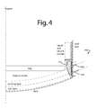
- FIG. 4 is a cross sectional view of another thrust block embodiment of the present invention in which cooling is included and the thrust rods press radially inward inline with the hearth brick working layer at the bottom of a circular furnace hearth;
- FIGS. 5A , 5 B, and 5 C are perspective, top and cross-sectional view diagrams of a furnace embodiment of the present invention like that of FIG. 1 , and incorporating elements like those in FIGS. 2A , 2 B, 3 , and 4 ; and
- FIG. 6 is a simplified half section and perspective cutaway diagram of a furnace embodiment of the present invention like that of FIGS. 1 , 5 A, 5 B, and 5 C, and incorporating elements like those in FIGS. 2A , 2 B, 3 , and 4 .
- FIG. 1 represents a furnace refractory brick hearth system embodiment of the present invention, and is referred to herein by the general reference numeral 100 .
- the system 100 comprises an outer, rigid steel containment shell 102 having a dished bottom 104 and circular vertical walls 106 .
- the bottom is lined with hearth refractory in one or more sub-layers like sub-layer 108 , over which is placed a hearth brick working layer 110 .
- Such hearth refractory may comprise individual bricks.
- the outer perimeter of the hearth brick working layer 110 supports a wall brick 112 .
- Gravity keeps the wall brick 112 tightly packed, and a ring of thrust blocks 114 inwardly compress and compact the hearth brick working layer 110 .
- the radial compression towards the center is provided by many individual thrust rods 116 that each push inwardly against corresponding thrust blocks 114 .
- the thrust rod forces are provided externally by adjustable spring assemblies 118 mounted on the outside of the shell wall 106 . Simple holes, or pushrod guides may be provided for the thrust rods in the containment shell 102 .
- the adjustable spring assemblies 118 take advantage of the hoop strength and solid construction of the shell wall 106 to generate the necessary leverage.
- the adjustable spring assemblies 118 are periodically set to a predetermined pressure value.
- the hearth brick working layer 110 will inevitably grow in diameter as molecules of molten metal are absorbed into the refractory brick material and the minute spaces between them. Such growth necessitates routine readjustment of the adjustable spring assemblies 118 , and so the conditions should be monitored.
- a relatively wide margin of space is provided between the outer edges of the thrust blocks 114 and the inside of shell wall 106 .
- Such can be filled with expansion boards or other crushable material that can be replaced or removed as the space diminishes. Fill material such as this is not required if a spring system embodiment of the present invention is sized to carry the full hearth load.
- the thrust blocks 114 are provided with circulating coolant to draw off heat, and may be made of copper or copper alloy.
- a wall cooler 120 may also be provided which has horizontally or vertically oriented layers.
- the thrust block 114 is intended to either replace the brick skew, or apply load directly to it.
- the thrust blocks as shown in FIGS. 1 , 3 and 4 , rise from the brick skew to the top of the molten bath.
- the typical commercial furnace hearth size ranges from two to fifteen meters in diameter.
- the radial spacing of the hearth compression thrust rods 116 depends on the forces required, the stiffness of the inside thrust blocks 114 , and should be arranged to avoid interference with tap holes and other openings. As an example, the spacing could be expected to range from one to two meters for larger diameter furnaces, or they could be arranged at 10-30 degree increments around the furnace shell 102 .
- Thrust rods 116 would generally be fabricated from steel, but may need to be made from metals that can resist corrosion and/or assist in cooling.
- the size and cross sectional shapes needed for the thrust rods 116 depend on the engineered forces required. Other contributing forces increase with the size of the hearth refractory, as well as the fluid pressure coming from the top of the hearth. The maximum fluid pressures will be observed at the hearth invert, or the lowest point of the hearth.
- the devices could be used to impart initial compression of the hearth, which could result in an initial net shrinkage.
- the devices could be designed to typically accommodate 50-150 mm of hearth expansion. On a percentage basis, up to practical maximum of two percent of the hearth diameter. For larger hearth movements, differential expansion between the wall and the hearth becomes unmanageable, and the required size of the compression rods becomes unreasonable.
- the minimum compression forces on the hearth refractory brick must be sufficient to keep interfacial pressures between the bricks greater than the fluid pressures trying to come between or float the bricks.
- One object is to limit penetration of molten metal, matte or slag that gets into the joints. Too rapid a penetration can induce a quicker than normal rate of expansion of the hearth over the long term. Too much molten metal penetration that gets under the bricks can cause individual bricks and sections of brick hearth to try to separate and float to the top of the matte. So, the hearth compression forces applied must be sufficient to maintain hearth stability, and overcome large buoyancy pressures if molten metals nevertheless get beneath the hearth brick working layer 110 .
- embodiments of the present invention supply sufficient hearth compression to maintain hearth stability, and apply the minimum compression needed to limit melt penetration between the joints, their long-term hearth refractory rate-of-growth will not exceed that observed in conventional current hearth designs. And the service life will be greatly increased at very modest cost.
- hearth expansion has been shown to be reduced with good hearth compression. Hence, increasing hearth compression could be used to reduce long-term hearth expansion.
- hearth expansion can be 2-50 millimeters (mm) after a furnace has been shut down cold and restarted. In usual practice, the expansion material must be replaced prior to the shell becoming overstressed.
- Corrosion can be an issue in those environments where corrosive gases are produced as part of the smelting process. Gases like SO 2 and SO, can readily form acids. Acid environments necessitate the use of stainless steel or nickel alloys to resist corrosion.
- Parts that may be exposed to high heat loads or molten materials may require cooling. If a component is to be cooled, it may be fabricated from a conductive alloy of copper or other metal, to minimize stresses and to reduce the potential for cracking.
- the internal member used for distributing the compressive forces to the hearth may be cooled with air, water or other heat transfer fluid or gas; it may have internal cooling passages for conveying the heat transfer fluid or gas.
- FIGS. 2A and 2B show two slightly different configurations 200 and 201 to couple spring pressure from the outside of the containment shell through to the inside using thrust rods that push in against the ring of thrust blocks around the hearth brick working layer.
- configuration 200 makes use of a load beam
- configuration 201 uses rocker arms.
- a hearth brick working layer 202 grows and presses outwardly against a ring of thrust blocks 204 .
- a number of thrust rods 206 and 208 pass through the outer wall of a containment shell 210 and will transmit inwardly directed pressures.
- a load beam 212 bridges over the ends of thrust rods 206 and 208 and presses against them using springs 214 and 216 , and adjustment nuts 218 and 220 , mounted on external studs 222 and 224 .
- the inward forces generated by the springs 214 and 216 are directed at an angle theta ( ⁇ ) 226 , e.g., 90-degrees to the central vertical axis of the furnace, or at some appropriate obtuse or acute angle relative to the shell wall 210 to put them inline with the outer edges of a dished bottom hearth brick working layer.
- ⁇ theta
- FIG. 2B shows the use of a pair of rocker arms 230 and 232 .
- the studs 222 and 224 allow adjusting nuts 218 and 220 to act as fulcrums.
- Adjusting nuts 218 and 220 are set at the beginning, and then reset during the service life of hearth brick working layer 202 as it grows.
- the amount of pressure applied by particular springs can be interpreted from compression charts according to their present compressed spring length. Other mechanisms could also be used to estimate thrust rod pressures to keep the furnace in proper tune.
- FIG. 3 shows a horizontal-type thrust block system embodiment of the present invention, and is referred to herein by the general reference numeral 300 .
- a copper-alloy thrust block 302 has internal water jackets to circulate a coolant and a tapered edge to press square against a hearth brick working layer.
- a pair of thrust rods 304 and 306 are pressed radially inward normal to the vertical axis of a circular furnace hearth by a spreader beam 308 . Adjustments to the thrust rod forces can be made by a pair of tie-rod and spring sets 310 and 312 .
- FIG. 4 shows an angled-type thrust block system embodiment of the present invention, and is referred to herein by the general reference numeral 400 .
- a copper-alloy thrust block 402 has internal water jackets to circulate a coolant and a tapered edge to press square against a hearth brick working layer.
- a pair of thrust rods 404 and 406 are pressed radially inward inline with the outer edges of a hearth brick working layer.
- thrust rod 404 or 406 could be horizontal while the other is inclined.
- the spring assemblies with rocker arms and/or spreader beams, as shown in FIGS. 2A , 2 B, and 3 for example could be adapted for use.
- Seals can be included around each thrust rod where it penetrates the furnace shell to control leakage. But, if the spring system is doing its job keeping the bricks tight, such seals would not be necessary.
- the refractory bricks inside a furnace are quite brittle. Uneven pressures on the bricks can allow uneven thermal expansion and possible break outs of molten material from the furnace.
- Embodiments of the present invention use a circular band portion of the vertical walls of the containment shell for evenly applied inward radial leverage like a barrel hoop. In this way, the shell maintains hoop tension and naturally resists distortions. Dozens of radial thrust rods are used to uniformly compress a ring of thrust blocks and the refractory brick they encircle inside the furnace.
- Heat transmission through the brick is improved by uniform compression of the refractory.
- the campaign life of the brick and the furnace is extended, because the rings of brick expand outward, increasing the pressures between the shell and the bricks.
- the bricks tend to pull away from the walls and coolers during each campaign because the bricks swell more on the hot faces than they do on the cooler backsides.
- the trapezoiding produces gaps between the lower edges of the brick, resulting in rapid erosion and chemical corrosion of the bricks. Such is well known to designers of circular and rectangular furnaces.
- a hearth shell plate bolted to a vertical shell plate is considered “one piece”.
- the shell at the level of the compression devices should be one piece. However, if openings are needed, they must be reinforced to maintain overall integrity of the shell.
- FIGS. 5A , 5 B, and 5 C represent a furnace embodiment of the present invention, and is referred to herein by the general reference numeral 500 .
- Furnace 500 has a bottom refractory layer 502 in a downwardly dished circular bottom, and a circular, vertical wall 504 of refractory brick inside a single-piece, vertical cylindrical containment shell 506 .
- a number of threaded studs 508 are fastened at intervals in two parallel planes around the outside of the containment shell 506 .
- a thrust bar 514 in each compression assembly 510 is able to slide in and out on vertical pairs of threaded radial studs 508 . Pairs of thrust springs 516 push the thrust bars 514 and thrust rods 512 radially inward against bottom refractory layer 502 using threaded radial studs 508 for leverage. Nuts (not shown) on the ends of the threaded radial studs 508 keep the springs 516 and allow some adjustment. Other spring arrangements are possible.
- springs 516 will compress but still maintain more-or-less even pressure all around the circular perimeter of bottom refractory layer 502 .
- a tap hole 520 is water cooled and allows molten material to be tapped out, according to the elevation of its placement. Different elevations provide for the tapping of slag (molten oxides solution floating on top), matte (molten metal sulfide phases), or molten metal (the heaviest and at the bottom).
- the ends 522 of water cooled copper blocks can be seen all around the outside of furnace 500 in FIG. 5A .
- FIG. 5C the threaded studs radial studs 508 in compression assembles 510 are tilted upwards at their ends to more closely align with the plane of bottom refractory layer 502 at its outer edges.
- Thrust ring 402 in FIG. 4 is the equivalent of a ring of thrust blocks 530 in FIG. 5C .
- the ring nature of this feature is shown more plainly in the simplification of FIG. 6 .
- a gap 532 outside the ring of thrust blocks 530 and inside the containment shell 506 provides room for the eventual expansion of the bottom refractory layer 502 over the campaign life.
- Each thrust block 530 has a face 534 configured to be perpendicular to the plane of the bottom refractory layer 502 at its circular outer edges.
- FIGS. 5A , 5 B, and 5 C show the bottom refractory layer 502 in the shape of a spherical cap. In some applications, the bottom refractory layer 502 may be in the form of a flat, round or circular disk.
- FIG. 6 represents a system 600 for applying and maintaining proper compression of brick hearth in a furnace refractory so as to extend its service life.
- System 600 comprises a plurality of thrust blocks, e.g., 601 - 609 , arranged in a thrust ring 610 with an inner face 612 for contacting an outer perimeter of a bedding of hearth brick.
- the thrust ring 610 is disposed in the bottom of a vertical cylindrical pyrometallergical furnace, e.g., inside a one-piece, non-segmented steel containment shell 612 .
- a plurality of thrust rods, e.g., 621 - 626 penetrate the containment shell and transmit inwardly radial compression forces to matching outer faces of corresponding ones of the plurality of thrust blocks 601 - 609 .
Landscapes
- Engineering & Computer Science (AREA)
- Mechanical Engineering (AREA)
- General Engineering & Computer Science (AREA)
- Chemical & Material Sciences (AREA)
- Combustion & Propulsion (AREA)
- Vertical, Hearth, Or Arc Furnaces (AREA)
- Furnace Housings, Linings, Walls, And Ceilings (AREA)
Abstract
Description
Claims (9)
Priority Applications (1)
| Application Number | Priority Date | Filing Date | Title |
|---|---|---|---|
| US12/700,721 US8325779B2 (en) | 2007-02-12 | 2010-02-05 | Wide-range round-bottom hearth-brick compression system |
Applications Claiming Priority (2)
| Application Number | Priority Date | Filing Date | Title |
|---|---|---|---|
| US11/674,123 US8446929B2 (en) | 2007-02-12 | 2007-02-12 | Furnace refractory brick hearth system |
| US12/700,721 US8325779B2 (en) | 2007-02-12 | 2010-02-05 | Wide-range round-bottom hearth-brick compression system |
Related Parent Applications (1)
| Application Number | Title | Priority Date | Filing Date |
|---|---|---|---|
| US11/674,123 Division US8446929B2 (en) | 2007-02-12 | 2007-02-12 | Furnace refractory brick hearth system |
Publications (2)
| Publication Number | Publication Date |
|---|---|
| US20100132599A1 US20100132599A1 (en) | 2010-06-03 |
| US8325779B2 true US8325779B2 (en) | 2012-12-04 |
Family
ID=39684749
Family Applications (2)
| Application Number | Title | Priority Date | Filing Date |
|---|---|---|---|
| US11/674,123 Expired - Fee Related US8446929B2 (en) | 2007-02-12 | 2007-02-12 | Furnace refractory brick hearth system |
| US12/700,721 Active - Reinstated 2028-04-14 US8325779B2 (en) | 2007-02-12 | 2010-02-05 | Wide-range round-bottom hearth-brick compression system |
Family Applications Before (1)
| Application Number | Title | Priority Date | Filing Date |
|---|---|---|---|
| US11/674,123 Expired - Fee Related US8446929B2 (en) | 2007-02-12 | 2007-02-12 | Furnace refractory brick hearth system |
Country Status (1)
| Country | Link |
|---|---|
| US (2) | US8446929B2 (en) |
Cited By (1)
| Publication number | Priority date | Publication date | Assignee | Title |
|---|---|---|---|---|
| US20130099432A1 (en) * | 2011-10-20 | 2013-04-25 | Allan Macrae | Furnace refractory brick hearth tap hole |
Families Citing this family (5)
| Publication number | Priority date | Publication date | Assignee | Title |
|---|---|---|---|---|
| US20090236233A1 (en) * | 2008-03-24 | 2009-09-24 | Alcoa Inc. | Aluminum electrolysis cell electrolyte containment systems and apparatus and methods relating to the same |
| EP3211307B1 (en) * | 2016-02-26 | 2019-06-05 | Jünger + Gräter GmbH Feuerfestbau | Protective refractory element |
| KR102893854B1 (en) * | 2021-02-24 | 2025-12-01 | 메트소 메탈즈 오이 | metallurgical furnace |
| US20240230234A9 (en) * | 2022-10-24 | 2024-07-11 | HarbisonWalker International Holdings, Inc. | Apparatus and method for preventing lining disruptions exposed to elevated temperature |
| CN119550466B (en) * | 2024-10-30 | 2025-12-02 | 宜兴市凯达耐火材料有限公司 | A molding and cutting equipment for processing ultra-lightweight, high-strength mullite-corundum lightweight bricks. |
Citations (9)
| Publication number | Priority date | Publication date | Assignee | Title |
|---|---|---|---|---|
| US3175961A (en) | 1962-05-28 | 1965-03-30 | Allied Chem | Adjusting device for springs associated with the buckstays of coke oven batteries |
| US3399267A (en) | 1966-08-15 | 1968-08-27 | Dresser Ind | Induction furnace |
| US4773630A (en) * | 1986-09-02 | 1988-09-27 | Shamprogetti S.P.A. | Tank furnace for the metallurgical treatment of non-ferrous metals |
| US4923397A (en) | 1988-04-29 | 1990-05-08 | T.T.C. Termo Tecnica Ceramica S.P.A. | Flat separation floor between two superposed chambers in kilns, in particular roller-hearth kilns for ceramic tiles |
| US5648981A (en) | 1994-11-22 | 1997-07-15 | Ucar Carbon Technology Corporation | Cooling system for a two component furnace roof |
| US5867523A (en) | 1996-05-28 | 1999-02-02 | Hatch Associates Ltd. | Electric furnace with conductive hearth |
| US6814012B2 (en) | 2002-10-11 | 2004-11-09 | Hatch Associates Ltd. | Furnace binding and adjustment systems |
| US6911176B2 (en) | 2000-11-01 | 2005-06-28 | Outokumpu Oyj | Cooling element |
| US20060196399A1 (en) * | 2005-03-02 | 2006-09-07 | Hatch Ltd. | Split shell circular furnace and binding systems for circular furnaces |
Family Cites Families (1)
| Publication number | Priority date | Publication date | Assignee | Title |
|---|---|---|---|---|
| CH671240A5 (en) | 1987-07-29 | 1989-08-15 | Jean Lathion |
-
2007
- 2007-02-12 US US11/674,123 patent/US8446929B2/en not_active Expired - Fee Related
-
2010
- 2010-02-05 US US12/700,721 patent/US8325779B2/en active Active - Reinstated
Patent Citations (9)
| Publication number | Priority date | Publication date | Assignee | Title |
|---|---|---|---|---|
| US3175961A (en) | 1962-05-28 | 1965-03-30 | Allied Chem | Adjusting device for springs associated with the buckstays of coke oven batteries |
| US3399267A (en) | 1966-08-15 | 1968-08-27 | Dresser Ind | Induction furnace |
| US4773630A (en) * | 1986-09-02 | 1988-09-27 | Shamprogetti S.P.A. | Tank furnace for the metallurgical treatment of non-ferrous metals |
| US4923397A (en) | 1988-04-29 | 1990-05-08 | T.T.C. Termo Tecnica Ceramica S.P.A. | Flat separation floor between two superposed chambers in kilns, in particular roller-hearth kilns for ceramic tiles |
| US5648981A (en) | 1994-11-22 | 1997-07-15 | Ucar Carbon Technology Corporation | Cooling system for a two component furnace roof |
| US5867523A (en) | 1996-05-28 | 1999-02-02 | Hatch Associates Ltd. | Electric furnace with conductive hearth |
| US6911176B2 (en) | 2000-11-01 | 2005-06-28 | Outokumpu Oyj | Cooling element |
| US6814012B2 (en) | 2002-10-11 | 2004-11-09 | Hatch Associates Ltd. | Furnace binding and adjustment systems |
| US20060196399A1 (en) * | 2005-03-02 | 2006-09-07 | Hatch Ltd. | Split shell circular furnace and binding systems for circular furnaces |
Non-Patent Citations (1)
| Title |
|---|
| T. Ma, et al., Recent Developments in DC Furnace Design, symposium paper presented in Montreal, Candada, Aug. 1999. |
Cited By (2)
| Publication number | Priority date | Publication date | Assignee | Title |
|---|---|---|---|---|
| US20130099432A1 (en) * | 2011-10-20 | 2013-04-25 | Allan Macrae | Furnace refractory brick hearth tap hole |
| US8574488B2 (en) * | 2011-10-20 | 2013-11-05 | Allan Macrae | Furnace refractory brick hearth tap hole |
Also Published As
| Publication number | Publication date |
|---|---|
| US20100132599A1 (en) | 2010-06-03 |
| US8446929B2 (en) | 2013-05-21 |
| US20080190336A1 (en) | 2008-08-14 |
Similar Documents
| Publication | Publication Date | Title |
|---|---|---|
| US8325779B2 (en) | Wide-range round-bottom hearth-brick compression system | |
| US9752830B2 (en) | Electrode seal for use in a metallurgical furnace | |
| US8574488B2 (en) | Furnace refractory brick hearth tap hole | |
| KR20040107204A (en) | An apparatus for automatically controlling the temperature and the shape of buckstay of oven battery | |
| ZA200501130B (en) | Cooling plate for metallurgic furnaces | |
| WO2016077931A1 (en) | Low-profile aluminum cell potshell and method for increasing the productivity of an aluminum cell potline | |
| US6843958B1 (en) | Copper cooling plate for metallurgical furnaces | |
| US5299225A (en) | Graphitization furnace | |
| US20080111287A1 (en) | Systems and Methods of Cooling Blast Furnaces | |
| US20240153653A1 (en) | Nuclear reactor with a liquid metal coolant | |
| US7544321B2 (en) | Process container with cooling elements | |
| EP3887737B1 (en) | Lining and cooling arrangement for a metallurgical furnace | |
| US7134397B2 (en) | System for applying vertical compressive force to furnace walls | |
| GB2093537A (en) | Seals | |
| CA2581979C (en) | Metallurgical furnace | |
| EP3950967A1 (en) | Blast furnace wall-cooling staves | |
| KR100284865B1 (en) | Rotor unit for rotary regenerative air preheater | |
| CN113390266A (en) | Cooling device for transition zone of smelting reduction furnace | |
| CN201793674U (en) | Steel coil bearing plate of hydrogen hood-type annealing furnace | |
| CN217781191U (en) | Combined cooling structure | |
| CN223050406U (en) | Heating element fixing assembly for heating chamber of vacuum furnace | |
| JP2009012015A (en) | Ladle | |
| JP2025129775A (en) | Blast furnace cooling structure | |
| SU831783A1 (en) | Blast furnace cooling device | |
| RU2124237C1 (en) | Core fixing device for pressurized-water reactor |
Legal Events
| Date | Code | Title | Description |
|---|---|---|---|
| REMI | Maintenance fee reminder mailed | ||
| FEPP | Fee payment procedure |
Free format text: PETITION RELATED TO MAINTENANCE FEES FILED (ORIGINAL EVENT CODE: PMFP); ENTITY STATUS OF PATENT OWNER: SMALL ENTITY |
|
| LAPS | Lapse for failure to pay maintenance fees | ||
| REIN | Reinstatement after maintenance fee payment confirmed | ||
| FEPP | Fee payment procedure |
Free format text: PETITION RELATED TO MAINTENANCE FEES GRANTED (ORIGINAL EVENT CODE: PMFG); ENTITY STATUS OF PATENT OWNER: SMALL ENTITY |
|
| FPAY | Fee payment |
Year of fee payment: 4 |
|
| SULP | Surcharge for late payment | ||
| FP | Lapsed due to failure to pay maintenance fee |
Effective date: 20161204 |
|
| PRDP | Patent reinstated due to the acceptance of a late maintenance fee |
Effective date: 20170523 |
|
| STCF | Information on status: patent grant |
Free format text: PATENTED CASE |
|
| STCF | Information on status: patent grant |
Free format text: PATENTED CASE |
|
| FEPP | Fee payment procedure |
Free format text: MAINTENANCE FEE REMINDER MAILED (ORIGINAL EVENT CODE: REM.); ENTITY STATUS OF PATENT OWNER: SMALL ENTITY |
|
| FEPP | Fee payment procedure |
Free format text: 7.5 YR SURCHARGE - LATE PMT W/IN 6 MO, SMALL ENTITY (ORIGINAL EVENT CODE: M2555); ENTITY STATUS OF PATENT OWNER: SMALL ENTITY |
|
| MAFP | Maintenance fee payment |
Free format text: PAYMENT OF MAINTENANCE FEE, 8TH YR, SMALL ENTITY (ORIGINAL EVENT CODE: M2552); ENTITY STATUS OF PATENT OWNER: SMALL ENTITY Year of fee payment: 8 |
|
| MAFP | Maintenance fee payment |
Free format text: PAYMENT OF MAINTENANCE FEE, 12TH YR, SMALL ENTITY (ORIGINAL EVENT CODE: M2553); ENTITY STATUS OF PATENT OWNER: SMALL ENTITY Year of fee payment: 12 |
|
| AS | Assignment |
Owner name: MACRAE, ALLAN J, MR., CANADA Free format text: ASSIGNMENT OF ASSIGNOR'S INTEREST;ASSIGNOR:MACRAE TECHNOLOGIES, INC.;REEL/FRAME:073229/0358 Effective date: 20251031 Owner name: MACRAE, ALLAN J, MR., CANADA Free format text: ASSIGNMENT OF ASSIGNORS INTEREST;ASSIGNOR:MACRAE TECHNOLOGIES, INC.;REEL/FRAME:073229/0358 Effective date: 20251031 |