US8325643B2 - Method for determining a sequence of access to a communications network, corresponding computer program product, storage means and devices - Google Patents
Method for determining a sequence of access to a communications network, corresponding computer program product, storage means and devices Download PDFInfo
- Publication number
- US8325643B2 US8325643B2 US12/596,415 US59641508A US8325643B2 US 8325643 B2 US8325643 B2 US 8325643B2 US 59641508 A US59641508 A US 59641508A US 8325643 B2 US8325643 B2 US 8325643B2
- Authority
- US
- United States
- Prior art keywords
- node
- nodes
- receiver
- relay
- determining
- Prior art date
- Legal status (The legal status is an assumption and is not a legal conclusion. Google has not performed a legal analysis and makes no representation as to the accuracy of the status listed.)
- Expired - Fee Related, expires
Links
- 238000004891 communication Methods 0.000 title claims abstract description 104
- 238000000034 method Methods 0.000 title claims abstract description 35
- 238000003860 storage Methods 0.000 title claims description 5
- 238000004590 computer program Methods 0.000 title description 3
- 230000006870 function Effects 0.000 claims description 9
- 230000005540 biological transmission Effects 0.000 description 81
- 238000012795 verification Methods 0.000 description 37
- 238000012545 processing Methods 0.000 description 11
- 238000005457 optimization Methods 0.000 description 7
- 230000000873 masking effect Effects 0.000 description 4
- 238000005259 measurement Methods 0.000 description 4
- 238000009826 distribution Methods 0.000 description 3
- 238000012937 correction Methods 0.000 description 2
- 235000008694 Humulus lupulus Nutrition 0.000 description 1
- 241001025261 Neoraja caerulea Species 0.000 description 1
- 230000001419 dependent effect Effects 0.000 description 1
- 238000010586 diagram Methods 0.000 description 1
- 230000000694 effects Effects 0.000 description 1
- 230000008030 elimination Effects 0.000 description 1
- 238000003379 elimination reaction Methods 0.000 description 1
- 238000003780 insertion Methods 0.000 description 1
- 230000037431 insertion Effects 0.000 description 1
- 238000007726 management method Methods 0.000 description 1
- 238000013433 optimization analysis Methods 0.000 description 1
- 238000002360 preparation method Methods 0.000 description 1
- 238000009877 rendering Methods 0.000 description 1
- 230000033764 rhythmic process Effects 0.000 description 1
- 230000001360 synchronised effect Effects 0.000 description 1
Images


Classifications
-
- H—ELECTRICITY
- H04—ELECTRIC COMMUNICATION TECHNIQUE
- H04W—WIRELESS COMMUNICATION NETWORKS
- H04W74/00—Wireless channel access
- H04W74/04—Scheduled access
-
- H—ELECTRICITY
- H04—ELECTRIC COMMUNICATION TECHNIQUE
- H04L—TRANSMISSION OF DIGITAL INFORMATION, e.g. TELEGRAPHIC COMMUNICATION
- H04L45/00—Routing or path finding of packets in data switching networks
-
- H—ELECTRICITY
- H04—ELECTRIC COMMUNICATION TECHNIQUE
- H04L—TRANSMISSION OF DIGITAL INFORMATION, e.g. TELEGRAPHIC COMMUNICATION
- H04L45/00—Routing or path finding of packets in data switching networks
- H04L45/48—Routing tree calculation
-
- H—ELECTRICITY
- H04—ELECTRIC COMMUNICATION TECHNIQUE
- H04W—WIRELESS COMMUNICATION NETWORKS
- H04W40/00—Communication routing or communication path finding
- H04W40/24—Connectivity information management, e.g. connectivity discovery or connectivity update
-
- H—ELECTRICITY
- H04—ELECTRIC COMMUNICATION TECHNIQUE
- H04W—WIRELESS COMMUNICATION NETWORKS
- H04W88/00—Devices specially adapted for wireless communication networks, e.g. terminals, base stations or access point devices
- H04W88/02—Terminal devices
- H04W88/04—Terminal devices adapted for relaying to or from another terminal or user
Definitions
- the field of the invention is that of the transmission of data contents in a communications network.
- the invention pertains especially to the transmission of data contents in a synchronous wireless home communications network comprising a plurality of receiver nodes and, more particularly, the transmission of contents in a 60 GHz radio transmission system.
- 60 GHz radio transmission systems are particularly well suited to the transmission of data at very high bit rate over short distances.
- a transmission system of this kind is well suited to connectivity between the different elements of a home cinema.
- the range of transmission is limited to about ten meters but the bit rates brought into play are very high, sometimes over one gigabyte per second, because of the nature (both audio and video) and the high resolution of the information transmitted.
- Each super frame comprises several frames containing the data to be transmitted.
- a wireless home communications network it is possible to ensure transmission time by dividing a network cycle into fixed time intervals (also called “frames” or “speech sequences”) so that each node uses one frame for the communication of data, each node thus sending in turn through its associated frame at predetermined points in time in a cycle of the communications network.
- frames also called “frames” or “speech sequences”
- speech sequences Such a technique is known as TDM (time division multiplex) or TDMA (time division multiple access) frequently used in wireless communications networks.
- burst transmission There is also another transmission technique known as burst transmission in which a large quantity of data is transmitted in a same frame, the frame being then no longer pre-defined.
- each node of the communications network sends out data it must transmit in a frame of the super-frame implemented in the network according to a predefined and invariable transmission sequence.
- TDMA mode or burst mode
- each node of the communications network sends out data it must transmit in a frame of the super-frame implemented in the network according to a predefined and invariable transmission sequence.
- At least one relay node which is a receiver of the content, retransmits the content to the receiver node (or destination node of the relay) in order to generate indirect communication between the source node and the receiver node that replaces the direct communication made non-operative by the obstacle.
- the invention in at least one embodiment, is aimed especially at overcoming these drawbacks of the prior art.
- Yet another goal of the invention in at least one of its embodiments, is to provide a technique of this kind that can be used to take account of the possibility of appearance of masking or shadowing in the topology of the network due to the temporary introduction of obstacles in the network.
- the invention in at least one of its embodiments, is also aimed at implementing a technique of this kind that is simple to use and costs little.
- a method for determining a sequence of access to a communications network by a plurality of nodes of said communications network in the context of the broadcasting of a data content by a sender or transmitter node to a set of receiver nodes, at least one receiver node having to receive said content by means of another receiver node, called a relay receiver node.
- the method of the invention comprises the following steps implemented by a manager device:
- the general principle of the invention in the context of the transmission of at least one content in a communications network, relies first of all on the making of a hierarchical tree comprising several relay levels or hop levels in which the plurality of nodes of the network is ordered in taking account of the topology of the network (especially the presence of obstacles in the network).
- the hierarchical tree thus obtained is then used to determine the ordering of the access of the nodes to the network in the context of the broadcasting of a content so as to minimize the time of transmission of the content in the network, in ensuring that a node that has to relay the content to at least one other node of the network can carry out the necessary processing needed for this data relay or data hop, such as for example processing operations associated with error correction or operations for reformatting data packets.
- the determining of at least one filial link includes a step for determining a piece of information representing a level of communications between the nodes of the communications network and the determining of the hierarchical tree is done as a function of said piece or pieces of information representing a level of communication.
- the information representing a level of communication between the nodes of the network is used to determine the relay nodes of the hierarchical tree in direct communication with the transmitter node.
- one of said rules of spatial diversity requires that a determined filial link should be selected to determine the hierarchical tree if the information representing a level of communications between the nodes linked by said filial link is greater than a predetermined threshold.
- one of said rules of spatial diversity requires that each of the receiver nodes should have two filial links in the hierarchical tree enabling it to receive the content.
- the criterion of spatial diversity dictates two filial links with which to ensure the reception of the data content by the receiver node despite the appearance of masking in the topology of the network due to the temporary introduction of obstacles into the network, while at the same time enabling the sequence of access to the network to provide for access by at least another node to the communications network between the access by a relay receiver node and access by the receiver node or nodes connected to it or to them by the filial links of the hierarchical tree.
- the hierarchical tree being constituted by as many branches as there are transmitter node antennas, one of said rules of spatial diversity dictates a balancing of the hierarchical tree relative to the transmitter node.
- This criterion of balancing of the hierarchical tree relative to the transmitter node provides for the delivery of an equitable distribution of the relay receiver nodes on each branch of the hierarchical tree, thus also minimizing transmission time for the data content in the network.
- This also enables a distribution of the dependencies of the nodes relative to one another for the broadcasting of the content and thus restricts the risks of non-reception of content by at least one of the nodes during the temporary masking that appears in the communications network.
- said sequence furthermore provides for access by a first receiver node to the communications network before a second receiver node in the sequence if at least one of the following criteria is verified:
- a computer program product downloadable from a communications network and/or recorded on a computer-readable support and/or executable by a processor, characterized in that it comprises program code instructions for the implementation of the method of determination as described here above.
- a computer-readable storage means which may be totally or partially detachable, storing a set of instructions executable by said computer to implement the determining method as described here above.
- a manager device is proposed to determine a sequence of access to a communications network by a plurality of nodes of said communications network in the context of the broadcasting of a data content by a transmitter node to a set of receiver nodes, at least one receiver node having to receive said content by means of another receiver node, called a relay receiver node.
- the manager device comprises:
- the means of determining at least one filial link comprise means of determining a piece of information representing a level of communications between the nodes of the communications network and the means of determining the hierarchical tree comprise means for taking account of said piece or pieces of information representing a level of communication.
- one of said rules of spatial diversity requires that a determined filial link should be selected to determine the hierarchical tree if the information representing a level of communications between the nodes linked by said filial link is greater than a predetermined threshold.
- one of said rules of spatial diversity requires that each of the receiver nodes should have two filial links in the hierarchical tree enabling it to receive the content.
- the hierarchical tree being constituted by as many branches as there are transmitter node antennas, one of said rules of spatial diversity dictates a balancing of the hierarchical tree relative to the transmitter node.
- said means for determining said sequence of access are such that said sequence furthermore provides for access by a first receiver node to the communications network before a second receiver node in the sequence if at least one of the following criteria is verified:
- a technique of this kind is compatible with a communications network implementing multipoint-to-multipoint type communications or point-to-multipoint type communications.
- FIG. 1 is a diagram of a communications network in which it is possible to implement a method for determining a sequence according to one particular embodiment of the invention
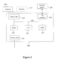
- FIG. 2 is an example of the simplified architecture of a generic node according to the particular embodiment of the invention.
- FIG. 3 illustrates the structure of a transmission super-frame according to the particular embodiment of the invention
- FIG. 4 presents the structure of a general table of RSSI information elements according to the particular embodiment of the invention.
- FIG. 5 presents examples of tables of neighboring nodes associated with the nodes of the communications network of FIG. 1 according to the particular embodiment of the invention
- FIG. 6 provides a detailed description of the main steps of an algorithm for building a hierarchical tree whose root is the WSC node 101 according to the particular embodiment of the invention
- FIG. 7 illustrates the hierarchical tree obtained after implementation of the algorithm of FIG. 6 and the use of the tables of neighboring nodes FIG. 5 according to an example of the particular embodiment of the invention
- FIG. 8 presents the main steps of the first part of an algorithm for determining the order of transmission of the sequence of frames of a super-frame according to the particular embodiment of the invention
- FIG. 9 describes the main steps of the second part of the algorithm for determining the order of transmission of the sequence of frames introduced by FIG. 8 according to the particular embodiment of the invention.
- a communications network 100 which is a 7.1 type home cinema or home theatre network as illustrated by FIG. 1 .
- the invention can also be applied in a 5.1 type home cinema network or even in any other communications network.
- the speakers are connected to an audio source by means of a wireless mesh network.
- the 7.1 home cinema network 100 comprises an audio-video source terminal (for example a DVD reader), a television screen (not illustrated), a first speaker 107 , called a subwoofer, a second speaker 102 , called a front-left speaker, a third speaker 103 , called a side-left speaker, a fourth speaker 104 , called a left ambience speaker, a fifth speaker 105 , called a center speaker, a sixth speaker 106 , called a front right speaker, a seventh speaker 108 , called a lateral right speaker, and an eighth speaker 109 , called a right ambience speaker.
- Each speaker plays one of the eight audio channels delivered by the source terminal.
- WSC Wireless Surround Controller
- Analog source devices for example the above-mentioned audio-video source terminal
- the communications network 100 can be connected to the WSC node 101 and the communications network 100 then enables the broadcasting of an audio contents given by the analog source to the different speakers of the home cinema.
- the function of a node WASi is to carry out an interface between the speaker with which it is associated and the WSC node 101 in the wireless mesh network.
- Each of the nodes namely the nodes WASi and the WSC node 101 is powered by means of a current connector (not shown).
- Each of the nodes WASi comprises an antenna (not shown) in order to implement wireless communications. This antenna is preferably an electronically controlled electromagnetic antenna.
- the WSC node 101 comprises a first antenna referenced R positioned on the right-hand side of the WSC node 101 and a second antenna referenced L positioned on the left-hand side of the WSC node 101 .
- the WSC node 101 can be integrated into the source terminal and each node WASi can be integrated into the speaker with which it is associated.
- 60 GHz radiofrequency (RF) transmission means or infrared (IR) transmission means are implemented in the communications network 100 .
- the communications network 100 can be subjected to interference or shadowing effects resulting from the presence of obstacles 110 or 111 .
- the WSC node is a transmitter of the audio content on the meshed network 100 and the nodes WASi are receivers of this audio content.
- each of the WSC and nodes WASi is capable of sending and receiving data, thus enabling the setting up of N-to-N or multipoint-to-multipoint type communications.
- the method for determining a sequence according to the invention is implemented in the form of a software program and/or a plurality of software sub-programs (comprising a plurality of algorithms described here below) which is/are executed in several machines of the network 100 , for example in the WSC node 101 (also called a manager device) and the nodes WASi.
- FIG. 2 a simplified architecture is presented of a generic node 200 identical to the WSC node or to each of the nodes WASi according to the particular embodiment of the invention.
- the generic node 200 comprises:
- an input/output controller 204 (also called an I/O controller) used for the connection of an external device 209 which may be:
- the generic node 200 also comprises:
- a processing unit 201 responsible for the management of the node 200 , and more specifically adapted to implementing the algorithms for applying the determining method according to the particular embodiment of the invention, described here below with reference to FIGS. 6 , 8 and 9 .
- ROM read-only memory
- a radio module 205 and its antenna 206 responsible for the transmission and reception of control and data information organized in a particular format.
- the radio module 205 applies adapted error correction means ensuring transmission of greater reliability on the radio frequency used.
- the radio module 205 works around the 60 GHz radio frequency channel. The level of transmission power does not enable all the nodes of the communications network 100 to receive information from any node of the network;
- a power supply module 207 responsible for supplying energy to all the components described here above.
- the WSC node 101 retrieves data from different audio channels designed to be processed by the nodes WASi each being associated with a given audio channel. This data is then organized within a frame to enable each WAS to extract the data intended for it. For example, the audio channel associated with a given WASi is identified by a piece of specific information such as the identifier of the node WASi. Then this data is sent to the radio module 205 of the WSC node 101 .
- DSP Digital signal processor
- each node WASi can extract and process the pieces of audio data intended for it from the received signal and then send these pieces of data to its associated media renderer device, which is an amplified audio speaker in the particular embodiment of the invention.
- the generic node 200 is a node WASi, it includes a single antenna 206 .
- this node 101 includes, as indicated here above, the first antenna R (also referenced 206 ) and the second antenna L (also referenced 210 ).
- the presence in the WSC node of two antennas provides for spatial diversity of emission so as to attenuate or even totally cancel a shadowing of the WSC node 101 .
- the super-frame structure 300 is periodically repeated at the rhythm of the network cycles.
- the super-frame 300 includes frames 301 in which each of the nodes of the network 100 (WSC node or node WASi) can transmit audio data and control data alternately.
- Two frames are sent by the WSC node 101 (or transmitter node) since it transmits data using two antennas ( 206 and 210 ).
- the data contained in the first frame is identical to the data contained in the second frame to ensure the reception of data transmitted by the WSC node by a majority of nodes WASi (or receiver nodes) of the network.
- the super-frame considered of the communications network 100 comprises NB_WAS+2 frames 301 (the first two frames being sent out by the WSC node 101 ).
- FIG. 3 provides a representation of the structure of a super-frame transmitted on the communications network 100 , the transmission time of which is equal to the duration of one cycle of the communications network 100 .
- this representation does not take account of the waiting time intervals between frames necessary to compensate for the jitter inherent in the wireless communications network 100 and the waiting time intervals between network cycles necessary for the synchronization of the clocks of the different nodes of the communications network 100 .
- each node WASi repeats the data of the WSC node 101 in the frame 301 that it sends.
- other nodes WASi can receive the data from the WSC node 101 even when they are initially not able to receive this data directly from the WSC node 101 .
- the order of transmission of the sequence of frames 301 of the super-frame 300 (also called a sequence of access) considered is stored in a frame transmission order table SF_Allocation of a size equal to NB_WAS+2.
- each unallocated index has an associated value equal to 0 and each index allocated to a node WASi has an associated value equal to an identifier proper to this node (the identifier proper to these nodes WASi being non-zero).
- the WSC node 101 determines the neighboring node tables or “neighbor tables” coming from the nodes WASi.
- a predetermined frame transmission order table (or network access) is used.
- each node WASi provides RSSI (received signal strength indicator) information elements, namely information representing a communications level, referenced Rinfo(WASi), in order to fill a general table of RSSI information elements referenced RSSI_Elt described here below with reference to FIG. 4 .
- RSSI received signal strength indicator
- RSSI_Elt RSSI information elements
- Each node WASi of the communications network 100 transmits the RSSI information elements corresponding to a received signal power indicator (or a communication level) when each of the other nodes, whether WSC or WAS, of the communications network 100 transmits. Furthermore, each node WASi of the communications network 100 transmits the RSSI information elements already obtained from the other node WASis of the communications network 100 . This ensures that the WSC node, shadowed from a node WASi by an obstacle, can nevertheless remember the RSSI information elements given by said node WASi.
- the RSSI (or Rinfo(WASi)) information elements 905 of a given node WASi comprises:
- each node WASi is capable of filling its own RSSI information element 905 with the most recent information since the other (WASi or WSC) nodes have transmitted data at least once on the communications network 100 .
- the RSSI information element Rinfo(WAS 2 ) includes its own measurement table for RSSI indicators (hereafter called an “RSSI table”) measured when other nodes of the communications network 100 transmit data.
- the other RSSI information elements (for example Rinfo(WAS 1 ), Rinfo(WAS 3 ), . . . Rinfo(WASN)) are used by the node WAS 2 to relay the RSSI tables of the associated WASj nodes (j different from i) and send them to the WSC node 101 (especially in order to secure the reception by this node of the RSSI tables when a masking or shadowing occurs).
- the information Rinfo(WASk) of the general table 900 must be updated with the content of Rinfo(WASk) received previously. If not, the information element Rinfo(WASk) of the general table 900 is already updated.
- the WSC node 101 is capable of receiving all the RSSI tables of each node WASi, including the tables of the node WASis that are incapable of transmitting data directly to the WSC node 101 (because of permanent shadowing).
- examples are presented of tables of neighboring nodes associated with the nodes of the communications network 100 , collected or obtained by the WSC node 101 during the above-mentioned phase of initialization of the communications network 100 .
- the WSC node can build the tables (referenced NT WASi ) of neighboring nodes associated with each of the node WASis of the network as well as the tables of neighboring nodes associated with the left antenna L (or WSC-L) and right antenna R (or WSC-R) of the WSC node (the tables being respectively referenced NT WSC-L and NT WSC-R ).
- the WSC node can determine the nodes of the communications network from which it can receive data with sufficient power level (or communications level). If the power level corresponding to a piece of RSSI information is lower than a predefined threshold, the WSC node will conclude that the communication between the nodes concerned does not offer sufficient reliability and that a link of this kind cannot be kept in the hierarchical tree targeted by the algorithm of FIG. 6 . In other words, the WSC node, in determining the hierarchical tree, keeps only the links corresponding to a piece of information on communications level higher than a predefined threshold.
- the WSC node 101 has obtained the tables of neighboring nodes of each of the nodes WASi as well as those of the antennas WSC-R and WSC-L.
- a table of neighboring nodes (NT WASi ) associated with a node WASi comprises a list of nodes among the nodes WASj (j different from i), and among the antennas WSC-R and WSC-L of the WSC node 101 for which the node WASi has an RSSI indicator value above a given threshold.
- the nodes WASj (j different from i) carried into the table of neighboring nodes of the node WASi are classified by an increasing RSSI indicator value.
- the node WAS 2 can receive data only from the node WAS 1 and from the node WAS 3 , and that the node WAS 1 can receive data from the right-hand antenna of the node WSC 101 (or WSC-R).
- the node WAS 1 in taking account of the processing time at the reception of data, is not capable of free transmitting the data delivered by the WSC node 101 during the same network cycle. Consequently, the node WAS 2 relies solely on the node WAS 3 to receive the data delivered by the node WSC 101 during the same network cycle.
- a time lag in the delivery of the data N is introduced at the level of the node WAS 2 , the node WAS 1 being only capable of retransmitting the data of a network cycle N in the super-frame of the next network cycle N+1.
- the determining method according to the particular embodiment of the invention is used to reduce the transmission time in the network of this data in contributing in order of transmission of the sequence of frames that is optimized as a function of the topology of the network.
- the WSC node 101 obtains all the neighbor tables associated with the different nodes WASi as described here above.
- the WSC node 101 obtains and then sorts out its own neighbor tables NT WSC-L and NT WSC-R .
- the step 505 is used to verify that a given node WASi is identified as a neighboring node belonging to a first relay level of the tree (or “one hop” level) for each radio antenna 206 and 210 of the WSC node 101 .
- this node uses a criteria of best reception to set up the hierarchical tree.
- this sorting operation can take account of a criterion (also called a balancing criterion) based on the size of the neighbor table to perform the most equitable possible distribution of the neighbor relay or hop nodes of the first level, on each antenna 206 and 210 of the WSC node 101 .
- a criterion also called a balancing criterion
- the method is aimed at trying to obtain a situation where the size of the table NT WSC-L is almost equal to that of the table NT WSC-R . This is done by the elimination, from the biggest sized table, of the identifier of the node WASi present in both tables.
- the simplified tables corresponding to the tables NT WSC-L and NT WSC-R respectively include ⁇ WAS 5 , WAS 6 , WAS 7 ⁇ and ⁇ WAS 1 , WAS 3 ⁇ .
- a step 510 the initialization of the variables dedicated to the creation of a hierarchical tree is performed.
- a variable known as “Table_In_Use” is allocated to an identifier of the table NT WSC-L in order to indicate that the analysis starts by the processing of the neighbor table from the viewpoint of the left-hand antenna of the WSC node.
- a “Current_tree_level” variable set at 1 to indicate that the processing in progress determines the first relay level or first hop level of the hierarchical tree starting from the WSC node 101 .
- NB_WAS_in_Tree used to ascertain that all the nodes WASi have been taken into account for the creation of the tree, is set at 0.
- each node of the neighbor table identified by the variable Table_In_Use is obtained incrementally, then added to the relay level or hop level of the hierarchical tree specified by the Current_tree_level variable.
- the NB_WAS_in_Tree variable is incremented by one unit.
- the value Nb_Parents of the node WASi considered is incremented by one unit, and the variable considered Tree level takes the value of the variable Current_tree_level.
- a check is made to see whether the node WASi of the neighbor table considered that has been added is the last of the table.
- the next node of the table is processed in the step 515 .
- step 525 it is ascertained in a step 525 that the analysis has been made for both antennas of the WSC node 101 .
- This check consists in verifying that the value of the variable Table_In_Use is different from NT WSC-R .
- a step 530 consists in allocating the value NT WSC-R to the variable Table_In_Use in order to carry out the analysis of the second table of the WSC node 101 .
- the steps 515 to 525 are then executed identically to what was described here above.
- the first step of creation of the hierarchical tree has been performed.
- the result of this first step of creation is a first hop level (as illustrated in FIG. 7 described here below) in which a first branch set up from the left antenna of the WSC node 101 (referenced WSC-L) is formed by WAS 5 , WAS 6 and WAS 7 , and a second branch set up from the right-hand antenna (referenced WSC-R) is formed by WAS 1 and WAS 3 .
- step 535 it is ascertained in a step 535 that all the WASi are already elements of the hierarchical tree in verifying that NB_WAS_in_Tree is equal to NB_WAS.
- any new node WASi to be added to the tree is a node of the second hop level from the viewpoint of the WSC node 101 .
- variable Current_tree_level is implemented by one unit in a step 540 .
- the description now relates to the study of the neighbor tables for each node WASi belonging to the first hop level of the hierarchical tree.
- NT WAS-x one of the neighbor tables for nodes neighboring the node WASi, named NT WAS-x is studied. For example, starting from FIG. 6 and maintaining the order of study of the first step in the creation of the hierarchical tree, a study is made of the tables of the first-level relay or hop nodes for the tree considered in the following order: NT WAS-5 , NT WAS-6 , NT WAS-7 , then NT WAS-1 , and NT WAS-3 .
- a step 550 it is ascertained hat the nodes of this table have not been previously added to the first hop level of the hierarchical tree. This verification can be done by verifying, for a node WASi, that the Tree_Level variable is not zero (initial value) and is lower than the variable Current_tree_level.
- a check is made, in a following step 555 , to see whether this node WASi is present at the hop level under study of the hierarchical tree (for example in verifying that the variable Tree_Level associated with it is equal to the variable Current_tree_level) and that the variable Nb_Parents associated with it is at least equal to 2 (which is an example of the rules of spatial diversity).
- the node WASi is added to the hierarchical tree, in a step 560 , in allocating the variable Tree_Level, associated with it the value of the variable Current_tree_level and in incrementing the variable Nb_Parents by one unit.
- the counter NB_WAS_in_Tree is implemented by one unit only if the variable Tree_Level is not equal to the variable Current_tree_level before the execution of the step 560 (so as not to count the insertion of the node WASi into the hierarchical tree twice).
- step 565 it is ascertained, in a step 565 , that all the nodes of the neighbor table of nodes neighboring the node WASi considered have been analyzed.
- the algorithm returns to the step 545 .
- step 570 it is ascertained in a step 570 that all the tables of the hop level studied (corresponding to the value of the variable Current_tree_level) of the tree have been analyzed.
- a study is made, in a step 575 , of the neighbor table of nodes neighboring the following node belonging to the hop level studied of the hierarchical tree, the steps of analysis and of creation of the tree starting again at the step 545 .
- step 570 In the event of positive verification step 570 (all the tables of the hop level considered have been analyzed), it is ascertained, in a step 535 , that all the nodes WASi have been included in the hierarchical tree.
- each branch of the tree delivered, from the WSC node 101 is ordered, to then authorize the application of the transmission order determining algorithm described with reference to FIGS. 8 and 9 .
- the node WASi having the greatest number of children or offspring and having the maximum hop levels is determined. This classification is made for each node WASi of the first hop level. This leads, for the branch associated with the antenna WSC-L, to the following order of transmission of the frames: WAS 6 , WAS 5 and WAS 7 , and for the branch associated with the antenna WSC-R it leads to the following order of transmission: WAS 3 , WAS 1 .
- the WSC node 101 uses the first two frames to transmit data, respectively by its left antenna WSC-L and by its right antenna WSC-R.
- This leads to the partial allocation of the variable SF_Allocation ⁇ WSC-L, WSC-R, NU, NU, NU, NU, NU, NU, NU, NU, NU, NU ⁇ where NU means that the index in the transmission sequence has not had been allocated.
- a variable “Slot_Type” is initialized at the value “even” in order to carry out the analysis of the branch of the tree associated with the left antenna WSC-L of the WSC node 101 (transmitting in even-order frames 0 ) so as to allocate an even frame sequence number to each of the WAS nodes of the first hop level of the tree. This enables them, as relay nodes, to have sufficient processing time available to retransmit the data received to the receiver nodes that are destinations of hops (these nodes may also be relay nodes) of the next hop level (second hop level) in a frame of the super-frame N.
- the variable Slot_Type indicates the even or odd character of a frame within the sequence of frames of the super-frame.
- variable Branch_Study is also initialized at the value WSC-L in order to start by the processing of the left branch of the hierarchical tree, i.e. the one associated with the antenna WSC-L.
- a step 710 the algorithm is set to start the determining of the index of transmission of the frames allocated to the nodes of the first hop level.
- the variable Current_tree_level is set at 1.
- An operation of this kind complies with the hierarchy of the tree obtained after implementation of the tree-building algorithm described with reference to FIG. 6 .
- a step 715 the first nodes WASi of the hierarchical tree are analyzed in starting with the left branch associated with the antenna WSC-L (in this case the node WAS 6 as determined in the step 580 ), then in a step 720 , a check is made to see if the node WASi considered has a child in the hierarchical tree.
- a first determining of order of frames is made in a step 725 in allocating the first available frame that verifies the parity criterion laid down by the variable Slot_Type (which, in the present case, has the “even” value) in the frame transmission order table SF_Allocation.
- a step 730 it is verified that all the nodes WASi of the levels studied of the tree (identified by the variable Current_tree_level) have been taken into account in determining the order of transmission of the frames.
- no determining of frame transmission order is set up for the node studied because, since no other node is dependent on the node studied, this node can use any unspecified frame.
- the case here is that of the nodes WAS 5 and WAS 7 , these two nodes having no children.
- SF_Allocation ⁇ WSC-L, WSC-R, WAS 6 , NU, NU, NU, NU, NU, NU, NU ⁇ .
- the following hop level (second hop level) of the hierarchical tree is studied in a step 735 to determine the index of transmission of the frames allocated to the nodes belonging to this second hop level of the left branch (associated with the antenna WSC-L).
- the variable Current_tree_level is incremented by 1.
- a node WASi of the hop level considered (in this case the second hop level) of the tree is analyzed.
- the analysis of the second hop level of the step 740 consists in determining the frame transmission index allocated to the nodes WAS 4 and WAS 8 .
- a step 745 it is verified that the frame transmission index allocated to the node WASi considered of the hop level considered in the sequence has not already been determined. This step 745 consists in verifying that the variable Slot_Number associated with it is not null.
- a new determining of the order in the sequence is done at a step 750 which allocates the first frame index available in the frame transmission order table SF_Allocation to the variable Slot_Number and verifies the parity criterion dictated by the parameter Slot_Type.
- the node WASi is henceforth analyzed.
- a step 755 it is verified that all the elements of the hop level represented by the variable Current_tree_level of the branch studied in the hierarchical tree have been analyzed.
- the following node WASi is analyzed in the step 740 to 755 .
- step 765 it is verified in a step 765 that all the hop levels of the branch studied had been analyzed in comparing the value of the variable Current_tree_level with the maximum number of hop levels of the branch under study.
- SF_Allocation ⁇ WSC-L, WSC-R, WAS 6 , NU, WAS 4 , NU, WAS 8 , NU, NU, NU ⁇ .
- WASi Nb_Parents Slot_Number Tree_Level To_be_optimized WAS1 1 0 1 FALSE WAS2 2 0 2 FALSE WAS3 1 0 1 FALSE WAS4 2 4 2 FALSE WAS5 1 0 1 FALSE WAS6 1 2 1 FALSE WAS7 1 0 1 FALSE WAS8 2 6 2 FALSE
- a step 770 it is ascertained that the order of the frames has also been determined for the right branch of the hierarchical tree (associated with the right antenna WSC-R) in verifying that the value of the variable Branch_Study has taken the value WSC-R.
- variable Branch_Study in a step 775 takes the value WSC-R in order to analyze the other branch of the hierarchical tree, and the variable Slot_Type takes the value “odd”.
- the step 775 is done before repeating the steps 710 to 765 described here above.
- SF_Allocation ⁇ WSC-L, WSC-R, WAS 6 , WAS 3 , WAS 4 , WAS 1 , WAS 8 , NU, NU, NU ⁇ .
- the analysis of the second level of the branch WSC-R (including the nodes WAS 4 , WAS 8 and WAS 2 ) enables verification that the nodes WAS 4 and WAS 8 have already been analyzed.
- the value TRUE is allocated to the variable To_be_optimized of the nodes WAS 4 and WAS 8 in order to subsequently check and see whether the frame transmission index assigned to each of these nodes can be optimized in order to enable them to receive data from their various parents in the hierarchical tree.
- variable Branch_Study has the value WSC-R, and following the positive verification at the step 770 , the method of the invention executes the second part of the determining algorithm described here below with reference to FIG. 9 .
- the second part of the determining algorithm is used to optimize, when possible, the frame transmission order to enable the reception, by a WASi node, of the signals coming from several parents of said WASi node before it transmits its frame in the super-frame.
- a first step 800 the optimizing phase starts with the study of the level from which it is possible to have multiple parents. In the case described here above, this corresponds to the second level of the hierarchical tree of FIG. 7 (the variable Current_tree_level is equal to 2). It must be noted that a possible optimization of this initialization is the initialization of the variable Current_tree_level at the value of the hop level subjected to the lowest optimization determined during the step 760 of FIG. 8 ).
- each node WASi of the hop level studied, having an associated variable Tree_Level value equal to the value of the variable Current_tree_level, is analyzed.
- a check is made to see whether an analysis of optimization of a given node is required (the variable To_be_optimized is then equal to the value TRUE) to improve the frame transmission order.
- a step 830 the frame transmission index allocated to the node WASi considered is not modified (the variable Slot_Number associated with WASi is unchanged) and the node WASi is listed as “analyzed” (the variable To_be_optimized associated with the node WASi being reset at FALSE).
- the frame transmitted in sequence by the node WASi considered is at a distance of at least two frames from the frames transmitted in the sequence by the parents of the node WASi, for example in comparing the values of the variables Slot_Number of the node WASi and of its parent nodes (i.e. there is a frame planned in the sequence between the element “NU” and the frames allocated to the parents of the node WASi).
- the frame transmission index allocated to the node WASi is already optimal. It is therefore not necessary to modify the order of the frame of the node WASi considered.
- the value of To_be_optimized of the WASi node considered may take the value FALSE (step 830 ) (this is for example the case with the node WAS 8 ).
- At least one frame between the frame transmitted by the node WASi and the ones sent by its parents is necessary so that the node WASi has sufficient time available to process the data received (concealed errors, preparation of data for retransmission etc).
- a check is made, in a step 820 , to find out if there is a frame free enabling the node WASi considered to receive data from its parents.
- the verification of the step 820 may consist of a search for an unused element “NU” of the transmission order table SF_Allocation for which the order (or index) of transmission is greater by at least two units relative to the maximum of the variable Slot_Number associated with the frames allocated to the parents of the node WASi (i.e. there is a frame planned in the sequence between the element “NU” and the frames allocated to the parents of the node WASi).
- this checking operation could be applied during the step 750 of the first part of the algorithm described with reference to FIG. 8 when no frame index corresponding to the parity criterion defined by the variable Slot_Type is available.
- the frame transmission index allocated to the analyzed node WASi is modified by the allocation to it of the location of the corresponding element NU (the value SF_Allocation[location of NU] takes the value “WASi”, the value SF_Allocation[Slot_Number of WASi] takes the value 0 and the variable Slot_Number of WASi takes the value of the location previously occupied by the element NU considered in the order of transmission).
- the value of the variable To_be_optimized of the node WASi considered takes the value FALSE, and the value of the variable Slot_Number associated with the node WASi is updated with the value of the variable of the frame NU considered.
- the characteristics of the node WAS 4 are then modified.
- a step 835 it is verified that all the nodes which belong, according to the hierarchical tree, to the hop level identified by Current_tree_level have been optimized.
- variable Current_tree_level is increased by one unit to enable an analysis of optimization of subsequent determining of order of the other levels of the tree in a step 840 .
- a verification step 845 is used to check on whether all the hop levels of the tree have undergone an optimization analysis.
- a step 850 is implemented.
- a step 850 an examination is carried out to find out if there are remaining WASi nodes to which no index in the transmission sequence has been allocated, in verifying that the value of the variable Slot_Number associated with them is equal to 0.
- the determining algorithm stops in a step 860 .
- a step 855 is used to determine the first free index which will be allocated to the node considered (to which no index in the transmission sequence has yet been allocated) and then the operation returns to the step 850 .
- the node considered is determined as being “determined”.
- SF_Allocation ⁇ WSC-L, WSC-R, WAS 6 , WAS 3 , WAS 5 , WAS 1 , WAS 8 , WAS 2 , WAS 4 , WAS 7 ⁇ .
- a processing operation making it possible to broadcast the new frame transmission order to the different nodes of the network can be implemented according to the same principle as the one applied to the propagation of the RSSI tables described here above with reference to FIG. 4 .
Landscapes
- Engineering & Computer Science (AREA)
- Computer Networks & Wireless Communication (AREA)
- Signal Processing (AREA)
- Mobile Radio Communication Systems (AREA)
- Data Exchanges In Wide-Area Networks (AREA)
Applications Claiming Priority (3)
| Application Number | Priority Date | Filing Date | Title |
|---|---|---|---|
| FR0755799 | 2007-06-15 | ||
| FR0755799 | 2007-06-15 | ||
| PCT/EP2008/057429 WO2008152113A1 (en) | 2007-06-15 | 2008-06-12 | Method for determining a sequence of access to a communications network, corresponding computer program product, storage means and devices |
Publications (2)
| Publication Number | Publication Date |
|---|---|
| US20100195556A1 US20100195556A1 (en) | 2010-08-05 |
| US8325643B2 true US8325643B2 (en) | 2012-12-04 |
Family
ID=39149133
Family Applications (1)
| Application Number | Title | Priority Date | Filing Date |
|---|---|---|---|
| US12/596,415 Expired - Fee Related US8325643B2 (en) | 2007-06-15 | 2008-06-12 | Method for determining a sequence of access to a communications network, corresponding computer program product, storage means and devices |
Country Status (5)
| Country | Link |
|---|---|
| US (1) | US8325643B2 (ja) |
| EP (1) | EP2165476B1 (ja) |
| JP (1) | JP5181021B2 (ja) |
| AT (1) | ATE535084T1 (ja) |
| WO (1) | WO2008152113A1 (ja) |
Cited By (1)
| Publication number | Priority date | Publication date | Assignee | Title |
|---|---|---|---|---|
| US10779214B2 (en) | 2016-09-27 | 2020-09-15 | Ricoh Company, Ltd. | Multi-hop communication |
Families Citing this family (7)
| Publication number | Priority date | Publication date | Assignee | Title |
|---|---|---|---|---|
| FR2948246B1 (fr) * | 2009-07-15 | 2011-09-09 | Canon Kk | Procede et dispositif d'allocation de bande passante liberee dans un reseau de communication, produit programme d'ordinateur et moyen de stockage correspondants |
| FR2951340B1 (fr) * | 2009-10-14 | 2012-08-10 | Canon Kk | Procede de gestion d'acces a un reseau de communication resistant aux masquages, produit programme d'ordinateur et dispositifs correspondants. |
| FR2951347B1 (fr) * | 2009-10-14 | 2011-11-11 | Canon Kk | Procede de gestion d'une repartition de bande passante dans un reseau de communication, produit programme d'ordinateur, moyen de stockage et noeud esclave correspondant. |
| FR2952268B1 (fr) * | 2009-10-30 | 2011-12-09 | Canon Kk | Procede et dispositif de gestion de communications dans un reseau sans fil, produit programme d'ordinateur et moyen de stockage correspondants. |
| FR2954659B1 (fr) * | 2009-12-23 | 2012-06-15 | Canon Kk | Procede de determination d'une sequence de noeuds, produit programme d'ordinateur, moyen de stockage et dispositif correspondants. |
| US20140242913A1 (en) * | 2013-01-01 | 2014-08-28 | Aliphcom | Mobile device speaker control |
| JP2017103586A (ja) | 2015-12-01 | 2017-06-08 | 株式会社リコー | 無線通信システム、無線通信装置、及びプログラム |
Citations (11)
| Publication number | Priority date | Publication date | Assignee | Title |
|---|---|---|---|---|
| US6229799B1 (en) * | 1995-10-02 | 2001-05-08 | Canon Kabushiki Kaisha | Methods, devices and systems for sharing a transmission medium, and a transmission method, communication devices and communication systems implementing these |
| US20030091014A1 (en) | 1991-10-01 | 2003-05-15 | Meier Robert C. | Radio frequency local area network |
| US6826401B1 (en) | 2000-01-14 | 2004-11-30 | Canon Europa, N.V. | Methods of automatic subscription between a mobile station and a base station in a telecommunications network, and systems implementing them |
| US7159042B1 (en) | 1999-03-04 | 2007-01-02 | Canon Kabushiki Kaisha | Method and device for communicating a message on a network and systems using them |
| US7185077B1 (en) * | 2000-01-25 | 2007-02-27 | Cisco Technology, Inc. | Methods and apparatus for managing the arrangement of nodes in a network |
| EP1772999A2 (en) | 2005-10-04 | 2007-04-11 | Samsung Electronics Co., Ltd. | Method of implementing multicast routing system in mobile ad-hoc network |
| US7299311B1 (en) * | 2005-12-29 | 2007-11-20 | Unisys Corporation | Apparatus and method for arbitrating for a resource group with programmable weights |
| US7468963B2 (en) * | 2004-06-07 | 2008-12-23 | Stmicroelectronics Belgium N.V. | Priority setting scheme for a wireless terminal |
| US20090143024A1 (en) | 2007-11-30 | 2009-06-04 | Canon Kabushiki Kaisha | Method of determining the instant of consideration of a modification of at least one reception condition for signals in a communication system |
| US20090161572A1 (en) | 2007-12-20 | 2009-06-25 | Canon Kabushiki Kaisha | method and a device for acknowledging data received by a communication device in a communication network |
| US7990927B2 (en) * | 2006-10-31 | 2011-08-02 | Infineon Technologies Ag | Method and apparatus for transmitting data in a communication system |
-
2008
- 2008-06-12 EP EP08760964A patent/EP2165476B1/en not_active Not-in-force
- 2008-06-12 AT AT08760964T patent/ATE535084T1/de active
- 2008-06-12 JP JP2010511651A patent/JP5181021B2/ja not_active Expired - Fee Related
- 2008-06-12 US US12/596,415 patent/US8325643B2/en not_active Expired - Fee Related
- 2008-06-12 WO PCT/EP2008/057429 patent/WO2008152113A1/en active Application Filing
Patent Citations (11)
| Publication number | Priority date | Publication date | Assignee | Title |
|---|---|---|---|---|
| US20030091014A1 (en) | 1991-10-01 | 2003-05-15 | Meier Robert C. | Radio frequency local area network |
| US6229799B1 (en) * | 1995-10-02 | 2001-05-08 | Canon Kabushiki Kaisha | Methods, devices and systems for sharing a transmission medium, and a transmission method, communication devices and communication systems implementing these |
| US7159042B1 (en) | 1999-03-04 | 2007-01-02 | Canon Kabushiki Kaisha | Method and device for communicating a message on a network and systems using them |
| US6826401B1 (en) | 2000-01-14 | 2004-11-30 | Canon Europa, N.V. | Methods of automatic subscription between a mobile station and a base station in a telecommunications network, and systems implementing them |
| US7185077B1 (en) * | 2000-01-25 | 2007-02-27 | Cisco Technology, Inc. | Methods and apparatus for managing the arrangement of nodes in a network |
| US7468963B2 (en) * | 2004-06-07 | 2008-12-23 | Stmicroelectronics Belgium N.V. | Priority setting scheme for a wireless terminal |
| EP1772999A2 (en) | 2005-10-04 | 2007-04-11 | Samsung Electronics Co., Ltd. | Method of implementing multicast routing system in mobile ad-hoc network |
| US7299311B1 (en) * | 2005-12-29 | 2007-11-20 | Unisys Corporation | Apparatus and method for arbitrating for a resource group with programmable weights |
| US7990927B2 (en) * | 2006-10-31 | 2011-08-02 | Infineon Technologies Ag | Method and apparatus for transmitting data in a communication system |
| US20090143024A1 (en) | 2007-11-30 | 2009-06-04 | Canon Kabushiki Kaisha | Method of determining the instant of consideration of a modification of at least one reception condition for signals in a communication system |
| US20090161572A1 (en) | 2007-12-20 | 2009-06-25 | Canon Kabushiki Kaisha | method and a device for acknowledging data received by a communication device in a communication network |
Non-Patent Citations (2)
| Title |
|---|
| Lagrange, et al., U.S. Appl. No. 12/626,741, filed Nov. 27, 2009. |
| Thoumy, et al., U.S. Appl. No. 12/686,699, filed Jan. 13, 2010. |
Cited By (1)
| Publication number | Priority date | Publication date | Assignee | Title |
|---|---|---|---|---|
| US10779214B2 (en) | 2016-09-27 | 2020-09-15 | Ricoh Company, Ltd. | Multi-hop communication |
Also Published As
| Publication number | Publication date |
|---|---|
| EP2165476B1 (en) | 2011-11-23 |
| WO2008152113A1 (en) | 2008-12-18 |
| JP2010531559A (ja) | 2010-09-24 |
| US20100195556A1 (en) | 2010-08-05 |
| EP2165476A1 (en) | 2010-03-24 |
| JP5181021B2 (ja) | 2013-04-10 |
| ATE535084T1 (de) | 2011-12-15 |
Similar Documents
| Publication | Publication Date | Title |
|---|---|---|
| US8325643B2 (en) | Method for determining a sequence of access to a communications network, corresponding computer program product, storage means and devices | |
| US20230231671A1 (en) | Fronthaul interface for advanced split-radio access network (ran) systems | |
| US8165170B2 (en) | Method for accessing a medium in a synchronous communications network by a transmit node, computer program product, storage means and transmit node | |
| CN102857327B (zh) | 一种数据传输方法和装置 | |
| US12047785B2 (en) | Management plane functionality for switched network shared cell configuration of open radio access network (O-RAN) system | |
| US8385324B2 (en) | Method and device for managing allocation of data transmission paths in a meshed communications network, corresponding computer program product and storage means | |
| US10321379B2 (en) | Method and apparatus for reducing the length of a packet storm in a wireless mesh network | |
| EP1981312A1 (en) | Method for assigning a plurality of audio channels to a plurality of speakers, corresponding computer program product, storage means and manager node | |
| US8326322B2 (en) | Methods for managing communications of a wireless communications network, corresponding storage means and devices | |
| US20160013857A9 (en) | Communication method for relay node and next node of the relay node for network coding | |
| CN108809475B (zh) | 一种通信参数确定方法及设备 | |
| US8503476B2 (en) | Communication method in a network comprising a primary network and a secondary network | |
| US8249519B2 (en) | Method of determining the instant of consideration of a modification of at least one reception condition for signals in a communication system | |
| CN103782645B (zh) | 用于重置网络站的系统和方法 | |
| US20050050219A1 (en) | Method for data streaming in ad-hoc wireless local area network | |
| CN112615662B (zh) | 一种低轨卫星的mac层的数据传输方法 | |
| US8089915B2 (en) | Synchronous data transmissions by relay node | |
| US7787427B1 (en) | Providing low average latency communication in wireless mesh networks | |
| US8397137B2 (en) | Method of decoding content data blocks, corresponding computer program product and decoding device | |
| KR20070105165A (ko) | Ip식별 패킷 구성 및 ip할당 장치, 이를이용한ip식별 패킷 구성 및 ip할당 방법 | |
| US8792463B2 (en) | Method for managing a distribution of bandwidth in a communications network, corresponding storage means and slave node | |
| US20200275453A1 (en) | Mode selection for mesh network communication | |
| US7742435B1 (en) | Providing a low latency backbone in a wireless mesh network | |
| WO2011008072A1 (en) | System and method for embedded mesh path management | |
| US8838720B2 (en) | Method for managing a distribution of bandwidth in a communications network, corresponding computer-readable storage medium and slave node |
Legal Events
| Date | Code | Title | Description |
|---|---|---|---|
| AS | Assignment |
Owner name: CANON KABUSHIKI KAISHA, JAPAN Free format text: ASSIGNMENT OF ASSIGNORS INTEREST;ASSIGNORS:TOCZE, LIONEL;NEZOU, PATRICE;CAILLERIE, ALAIN;AND OTHERS;REEL/FRAME:024188/0136 Effective date: 20100319 |
|
| REMI | Maintenance fee reminder mailed | ||
| LAPS | Lapse for failure to pay maintenance fees | ||
| STCH | Information on status: patent discontinuation |
Free format text: PATENT EXPIRED DUE TO NONPAYMENT OF MAINTENANCE FEES UNDER 37 CFR 1.362 |
|
| FP | Lapsed due to failure to pay maintenance fee |
Effective date: 20161204 |