US8325574B2 - Optical disc device - Google Patents
Optical disc device Download PDFInfo
- Publication number
- US8325574B2 US8325574B2 US12/336,555 US33655508A US8325574B2 US 8325574 B2 US8325574 B2 US 8325574B2 US 33655508 A US33655508 A US 33655508A US 8325574 B2 US8325574 B2 US 8325574B2
- Authority
- US
- United States
- Prior art keywords
- optical disc
- drive signal
- variation
- signal
- actuator
- Prior art date
- Legal status (The legal status is an assumption and is not a legal conclusion. Google has not performed a legal analysis and makes no representation as to the accuracy of the status listed.)
- Expired - Fee Related, expires
Links
Images


Classifications
-
- G—PHYSICS
- G11—INFORMATION STORAGE
- G11B—INFORMATION STORAGE BASED ON RELATIVE MOVEMENT BETWEEN RECORD CARRIER AND TRANSDUCER
- G11B7/00—Recording or reproducing by optical means, e.g. recording using a thermal beam of optical radiation by modifying optical properties or the physical structure, reproducing using an optical beam at lower power by sensing optical properties; Record carriers therefor
- G11B7/08—Disposition or mounting of heads or light sources relatively to record carriers
- G11B7/09—Disposition or mounting of heads or light sources relatively to record carriers with provision for moving the light beam or focus plane for the purpose of maintaining alignment of the light beam relative to the record carrier during transducing operation, e.g. to compensate for surface irregularities of the latter or for track following
- G11B7/0941—Methods and circuits for servo gain or phase compensation during operation
-
- G—PHYSICS
- G11—INFORMATION STORAGE
- G11B—INFORMATION STORAGE BASED ON RELATIVE MOVEMENT BETWEEN RECORD CARRIER AND TRANSDUCER
- G11B7/00—Recording or reproducing by optical means, e.g. recording using a thermal beam of optical radiation by modifying optical properties or the physical structure, reproducing using an optical beam at lower power by sensing optical properties; Record carriers therefor
- G11B7/08—Disposition or mounting of heads or light sources relatively to record carriers
- G11B7/09—Disposition or mounting of heads or light sources relatively to record carriers with provision for moving the light beam or focus plane for the purpose of maintaining alignment of the light beam relative to the record carrier during transducing operation, e.g. to compensate for surface irregularities of the latter or for track following
- G11B7/0945—Methods for initialising servos, start-up sequences
-
- G—PHYSICS
- G11—INFORMATION STORAGE
- G11B—INFORMATION STORAGE BASED ON RELATIVE MOVEMENT BETWEEN RECORD CARRIER AND TRANSDUCER
- G11B7/00—Recording or reproducing by optical means, e.g. recording using a thermal beam of optical radiation by modifying optical properties or the physical structure, reproducing using an optical beam at lower power by sensing optical properties; Record carriers therefor
- G11B7/08—Disposition or mounting of heads or light sources relatively to record carriers
- G11B7/09—Disposition or mounting of heads or light sources relatively to record carriers with provision for moving the light beam or focus plane for the purpose of maintaining alignment of the light beam relative to the record carrier during transducing operation, e.g. to compensate for surface irregularities of the latter or for track following
- G11B7/095—Disposition or mounting of heads or light sources relatively to record carriers with provision for moving the light beam or focus plane for the purpose of maintaining alignment of the light beam relative to the record carrier during transducing operation, e.g. to compensate for surface irregularities of the latter or for track following specially adapted for discs, e.g. for compensation of eccentricity or wobble
- G11B7/0953—Disposition or mounting of heads or light sources relatively to record carriers with provision for moving the light beam or focus plane for the purpose of maintaining alignment of the light beam relative to the record carrier during transducing operation, e.g. to compensate for surface irregularities of the latter or for track following specially adapted for discs, e.g. for compensation of eccentricity or wobble to compensate for eccentricity of the disc or disc tracks
Definitions
- the present invention relates to an optical disc device configured to control a motor or an actuator.
- a drive device such as actuator, mounted on a disc device can drive the disc device at a higher speed when a larger drive current is applied. On the other hand, if the drive current is increased too high, chances of failure will increase.
- JP-A-8-265960 discloses “detecting an overcurrent corresponding to temperature by comparing between a drive current supplied to the actuator from the driver and a limit current changed according to the temperature, and then detecting that the drive current to the actuator has exceeded the limit current.”
- the optical disc device with the overcurrent detecting unit described in JP-A-8-265960 temporarily stops the incoming current when it detects an overcurrent. In this case, however, it is necessary to temporarily stop recording or reproducing on the disc. Even though the operation is stopped temporarily, if recording or reproducing takes place on the disc while noise is occurring, the optical disc device will immediately detect an overcurrent and stop. Particularly when the optical disc device is of inferior quality and a large amount of drive current continues to occur, chances are that reproduction cannot be continued regardless of the level of temperature detected.
- the present invention therefore has a task of making it possible to continue reproduction while reducing the possibility for failure of the actuator which results from an increase in the drive current.
- the optical disc device changes servo-control characteristics according to amounts of variation in a focus drive signal and/or a tracking drive signal each output from a control means to drive the actuator. In this manner, an increase in the range of variation in the actuator drive signals is suppressed.
- the servo-control characteristics may be changed not only by drive signals but also based on signals generated from a reflected light.
- the optical disc device changes output characteristics of a spindle drive signal according to an amount of variation in a spindle motor drive signal.
- FIG. 1 is a block diagram showing an optical disc device.
- FIG. 2 is a diagram showing signal waveforms on a normal disc and a poor-quality disc.
- FIG. 3 is a diagram showing a relation between amounts of variation in spindle motor drive signal and amounts of drive current.
- FIG. 4 is a servo control characteristic diagram.
- FIG. 5 is a flowchart.
- FIG. 6 is a diagram for explaining amounts of variation in spindle drive signal (SDS) and amounts of spindle motor drive current.
- FIG. 1 is a block diagram showing the configuration of an optical disc device.
- An optical disc 100 is read, written or erased by emitting a laser beam from an optical pickup 110 , and the disc is rotated by a spindle motor 101 driven by a spindle drive means 121 , which responds to a spindle motor drive signal (SDS) output from the a system control means 120 .
- SDS spindle motor drive signal
- Laser light emitted from the laser light source 111 is condensed as a light spot on the information recording surface of the optical disc 100 by an objective lens 113 moved by the actuator 112 .
- a laser beam in a condensed light spot is reflected on the information recording surface of the optical disc 100 , and detected by a light detector 114 .
- the signal generating means 122 From a signal detected by the light detector 114 , the signal generating means 122 generates a focus error signal (FES) and a tracking error signal (TES).
- FES focus error signal
- TES tracking error signal
- a focus error signal is read as a signal representing an amount of error between the light spot and the information recording surface.
- a tracking error signal is read as a signal representing an amount of error in radial direction between the light spot and pits or a track provided in spiral form on the recording layer of the optical disc.
- the actuator 112 is driven by an actuator drive means 123 which responds to a focus drive signal (FDS) to move the actuator in the focus direction and a tracking drive signal (TDS) to move the actuator in the radial direction. Both of the drive signals are output from the system control means 120 . This actuator 112 moves the objective lens 113 in the radial direction and the focus direction of the optical disc 100 .
- the system control means 120 incorporates a signal variation amount measuring means 124 that measure amounts of variation of the two drive signals.
- FIG. 2 shows diagrams showing the behavior of a focus error signal and a focus drive signal, respectively, on a normal optical disc and on a poor-quality disc, the latter exhibits a reflected light containing noise, when an optical disc is being reproduced.
- the amount of variation of the focus error signal is large owing to noise in the reflected light, and therefore the amount of variation of the focus drive signal is also large, which is generated by passing the focus error signal through a filter.
- the increase of the focus drive signal causes an increase in the amount of current flowing in the actuator 112 , thus increasing the risk of breakdown of the actuator.
- FIG. 3 concerns a focus servo control system, and illustrates a relation between measured amounts by the signal variation amount measuring means 124 and amounts of current flowing in the actuator 112 after the optical disc 100 has rotated for a few rotations.
- the dots plotted in FIG. 3 represent the values obtained after the characteristics of a focus servo control system and a tracking servo control system with respect to the information recording surface of the optical disc 100 were adjusted and when the respective servo control systems were in operation.
- FIG. 3 shows results after several kinds of optical discs were set and ejected several times, and an initializing operation, such as a set-up process was performed more than once.
- Disc A has a relatively small amount of current, so it has a small measured value of the amount of variation.
- Discs B and C have large amounts of current and their actuators are at risk of breakdown. Therefore, the servo control characteristics of discs B and C are changed to suppress their amounts of current.
- Disc D sometimes exceeds FH 0 and sometimes does not exceed FH 0 , but neither case results in the actuator breakdown current being exceeded. It is desirable that FH 0 should be set with some allowance with respect to a dangerous amount of current.
- Changing characteristics of servo control performed on an optical disc which has a measured value of variation amount of FH 0 or more means to change the servo control characteristics in such a way as to suppress an amount of variation in actuator drive signals, namely a focus drive signal and a tracking drive signal.
- FIG. 4 shows an example of modification to the servo control characteristics.
- the amounts of variation in the actuator drive signal in the servo control system open-loop gain characteristics can be decreased by reducing the same amount of gain at every point of the original curve of the characteristics.
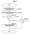
- FIG. 5 is a flowchart of this embodiment of the present invention.
- an initializing operation such as a set-up process and a loading process, is performed.
- the system control means 120 adjusts the servo control characteristics to obtain a desired control frequency band width (step 5 - 1 ).
- the system control means 120 measures amounts of variation in actuator drive signals (step 5 - 2 ).
- the system control means 120 determines whether or not a measured value of an amount of variation in the focus drive signal FH is smaller than the reference FH 0 of the focus servo control system (step 5 - 3 ). If the result of step 5 - 3 is Yes, the system control means 120 determines whether or not a measured value of an amount of variation in the tracking drive signal TH is smaller than the reference TH 0 of the tracking control system (step 5 - 4 ). If the result of step 5 - 4 is Yes, the system control means 120 finishes the process according to the servo control characteristics adjusted in step 5 - 1 . It the results in step 5 - 3 and step 5 - 4 are No, the system control means 120 finishes the process by changing the servo control characteristics, and reducing the amount of current (step 5 - 5 ).
- step 5 - 5 the system control means 120 changes the servo control characteristics of both the focus servo control system and the tracking servo control system.
- step 5 - 2 An example of a method of calculating an amount of variation in step 5 - 2 is described. For example, levels of each drive signal are measured at a fixed clock, and differences between measured levels and the reference level are obtained. An mount of variation of a drive signal is obtained by sequentially adding up the absolute values of differences or squared values of differences, or integrating the values of differences. Or, this amount of variation is obtained, for example, by sequentially adding up or integrating differences between maximum and minimum values of the oscillation of a drive signal. Furthermore, the amount of variation is obtained, for example, by applying the above-described method of calculation to drive signals obtained while the disc device rotates the disc several revolutions.
- a drive signal for one rotation or two rotations of the disc may be used, but these numbers are shown not for limitative purposes.
- the method for calculating amounts of variation may be configured that the measured amounts are calculated based on a drive signal obtained in a fixed period of time.
- step 5 - 5 for changing the characteristics of the focus servo control system and the tracking servo control system, there is a method which changes characteristics of only the control system where an amount of variation has exceeded a reference level. More specifically, if an amount of variation in a focus drive signal exceeds a reference value, the amounts of characteristics of the focus servo control system can be changed, or if an amount of variation in a tracking drive signal exceeds a reference value, the amounts of characteristics of the tracking servo control system can be changed.
- step 5 - 3 and step 5 - 4 are combined.
- the method of calculating amounts of variation may be configured to change servo characteristics based not on an amount of variation in the actuator drive signal, but on amounts of variation in the focus error signal and the tracking error signal.
- the method of calculating amounts of variation may be configured to accommodate a decrease in the servo control performance by decreasing the gain level, and reducing the rotating speed of the optical disc 100 . In this case, however, the transfer rate of information drops.
- amounts of variation of actuator drive signals are used as a factor for decision, but if an amount of current can be measured directly, this amount of current may be used as a factor for decision.
- An optical disc device in a second embodiment has the same structure as in the first embodiment shown in the block diagram of FIG. 1 .
- An optical disc is rotated by a spindle motor 101 driven by a spindle motor drive means 121 , which responds to a spindle motor drive signal (SDS) output from a system control means 120 .
- SDS spindle motor drive signal
- FIG. 6 illustrates a method of preventing a spindle motor drive current from surpassing the maximum level of specifications by using an amount of variation in a spindle motor drive signal.
- the optical disc device in both embodiments described, after an optical disc is inserted into the optical disc device, in the set-up process, a time is secured for a drive signal to be supplied until the optical disc has rotated for a few rotations. In this manner, a possibility of actuator breakdown due to overcurrent can be eliminated, so that after recording or reproduction is started subsequent to the set-up process, the possibility of operation stoppage caused by overcurrent can be suppressed. In the spindle motor, the possibility of rotation stop by excessive current can be suppressed.
- reproduction on an optical disc can be continued while the possibility of actuator failure owing to an increase in drive current is being suppressed.
Abstract
Description
Claims (18)
Applications Claiming Priority (2)
| Application Number | Priority Date | Filing Date | Title |
|---|---|---|---|
| JP2008038170A JP2009199642A (en) | 2008-02-20 | 2008-02-20 | Optical disk device |
| JP2008-038170 | 2008-02-20 |
Publications (2)
| Publication Number | Publication Date |
|---|---|
| US20090207708A1 US20090207708A1 (en) | 2009-08-20 |
| US8325574B2 true US8325574B2 (en) | 2012-12-04 |
Family
ID=40954996
Family Applications (1)
| Application Number | Title | Priority Date | Filing Date |
|---|---|---|---|
| US12/336,555 Expired - Fee Related US8325574B2 (en) | 2008-02-20 | 2008-12-17 | Optical disc device |
Country Status (3)
| Country | Link |
|---|---|
| US (1) | US8325574B2 (en) |
| JP (1) | JP2009199642A (en) |
| CN (1) | CN101515462B (en) |
Families Citing this family (1)
| Publication number | Priority date | Publication date | Assignee | Title |
|---|---|---|---|---|
| JP2011222070A (en) * | 2010-04-07 | 2011-11-04 | Hitachi-Lg Data Storage Inc | Optical disk drive and servo control method for actuator thereof |
Citations (8)
| Publication number | Priority date | Publication date | Assignee | Title |
|---|---|---|---|---|
| JPH08265960A (en) | 1995-03-23 | 1996-10-11 | Fujitsu Ltd | Overcurrent detection circuit |
| JPH09147392A (en) | 1995-09-18 | 1997-06-06 | Matsushita Electric Ind Co Ltd | Optical disk reproducing method and optical disk device |
| JPH11213407A (en) | 1998-01-27 | 1999-08-06 | Funai Electric Co Ltd | Servo controller |
| JP2003157547A (en) | 2001-11-22 | 2003-05-30 | Sharp Corp | Servo device |
| US20040085668A1 (en) * | 2002-10-31 | 2004-05-06 | Kabushiki Kaisha Toshiba | Disk drive and method for controlling driving voltage of spindle motor applied to disk drive |
| US20050162999A1 (en) * | 2003-01-20 | 2005-07-28 | Fujitsu Limited | Optical storage system and control method |
| JP2005222640A (en) | 2004-02-06 | 2005-08-18 | Shinano Kenshi Co Ltd | Optical disk device |
| US7843775B2 (en) * | 2006-06-30 | 2010-11-30 | Samsung Electronics Co., Ltd. | Optical disc apparatus and focusing method for the same |
Family Cites Families (1)
| Publication number | Priority date | Publication date | Assignee | Title |
|---|---|---|---|---|
| JP4373036B2 (en) * | 2001-08-31 | 2009-11-25 | パイオニア株式会社 | Optical pickup |
-
2008
- 2008-02-20 JP JP2008038170A patent/JP2009199642A/en active Pending
- 2008-11-20 CN CN2008101776546A patent/CN101515462B/en not_active Expired - Fee Related
- 2008-12-17 US US12/336,555 patent/US8325574B2/en not_active Expired - Fee Related
Patent Citations (8)
| Publication number | Priority date | Publication date | Assignee | Title |
|---|---|---|---|---|
| JPH08265960A (en) | 1995-03-23 | 1996-10-11 | Fujitsu Ltd | Overcurrent detection circuit |
| JPH09147392A (en) | 1995-09-18 | 1997-06-06 | Matsushita Electric Ind Co Ltd | Optical disk reproducing method and optical disk device |
| JPH11213407A (en) | 1998-01-27 | 1999-08-06 | Funai Electric Co Ltd | Servo controller |
| JP2003157547A (en) | 2001-11-22 | 2003-05-30 | Sharp Corp | Servo device |
| US20040085668A1 (en) * | 2002-10-31 | 2004-05-06 | Kabushiki Kaisha Toshiba | Disk drive and method for controlling driving voltage of spindle motor applied to disk drive |
| US20050162999A1 (en) * | 2003-01-20 | 2005-07-28 | Fujitsu Limited | Optical storage system and control method |
| JP2005222640A (en) | 2004-02-06 | 2005-08-18 | Shinano Kenshi Co Ltd | Optical disk device |
| US7843775B2 (en) * | 2006-06-30 | 2010-11-30 | Samsung Electronics Co., Ltd. | Optical disc apparatus and focusing method for the same |
Non-Patent Citations (1)
| Title |
|---|
| Machine translation of JP 09-147392A into English; Kusano et al. * |
Also Published As
| Publication number | Publication date |
|---|---|
| JP2009199642A (en) | 2009-09-03 |
| CN101515462A (en) | 2009-08-26 |
| US20090207708A1 (en) | 2009-08-20 |
| CN101515462B (en) | 2012-05-23 |
Similar Documents
| Publication | Publication Date | Title |
|---|---|---|
| US7995429B2 (en) | Optical disk device and tilt correction method thereof | |
| US8284648B2 (en) | Optical disk recording apparatus | |
| US7522485B2 (en) | Method for adjusting focus or tracking detection unit, and optical disc device | |
| US8223602B2 (en) | Optical disc drive | |
| JP3056441B2 (en) | DVD system disc identification method | |
| KR20080021153A (en) | Optimization of spherical aberration to determine current layer | |
| US8000194B2 (en) | Optical disc apparatus, method of adjusting focus offset for optical disc apparatus, and program for executing focus offset adjustment | |
| US8325574B2 (en) | Optical disc device | |
| US6724695B2 (en) | Method for accessing optical disk by detecting the different between moving command and actually moving | |
| EP1998330B1 (en) | Discrimination method for optical disc types and optical disc apparatus | |
| JP4547370B2 (en) | Optical disk device | |
| JP4168023B2 (en) | Optical disc apparatus and servo system adjustment method | |
| US20110205877A1 (en) | Optical disc drive and method for reading data from optical disc | |
| US20070133376A1 (en) | Read apparatus and a method of detecting deterioration of a disk | |
| US9177591B2 (en) | Focus controlling method and optical disk drive using the focus controlling method | |
| KR20060074856A (en) | Optical pickup tilt correction control unit and tilt correction method | |
| US20100124154A1 (en) | Signal processing devices and signal processing methods | |
| US7773474B2 (en) | Disc apparatus | |
| US20070201336A1 (en) | Method And Device For Writing Multiple-Layer Optical Discs | |
| US7983119B2 (en) | Optical disc apparatus | |
| US20070133363A1 (en) | Focus servo recovery processing method for optical disc device and optical disc device | |
| JP4951577B2 (en) | Disc playback apparatus and disc playback method | |
| JP2005332501A (en) | Information reproducing apparatus, information reproducing method, information reproducing program and information recording medium | |
| US20080137502A1 (en) | Optical disc apparatus and optical disc recording and reproducing method | |
| WO2010035334A1 (en) | Information recording/regenerating device and method |
Legal Events
| Date | Code | Title | Description |
|---|---|---|---|
| AS | Assignment |
Owner name: HITACHI, LTD., JAPAN Free format text: ASSIGNMENT OF ASSIGNORS INTEREST;ASSIGNORS:KATAOKA, TAKEYOSHI;IMAGAWA, SEIJI;YONEZAWA, MUNEHIRO;REEL/FRAME:022254/0497;SIGNING DATES FROM 20081204 TO 20081210 Owner name: HITACHI - LG DATA STORAGE, INC., JAPAN Free format text: ASSIGNMENT OF ASSIGNORS INTEREST;ASSIGNORS:KATAOKA, TAKEYOSHI;IMAGAWA, SEIJI;YONEZAWA, MUNEHIRO;REEL/FRAME:022254/0497;SIGNING DATES FROM 20081204 TO 20081210 Owner name: HITACHI - LG DATA STORAGE, INC., JAPAN Free format text: ASSIGNMENT OF ASSIGNORS INTEREST;ASSIGNORS:KATAOKA, TAKEYOSHI;IMAGAWA, SEIJI;YONEZAWA, MUNEHIRO;SIGNING DATES FROM 20081204 TO 20081210;REEL/FRAME:022254/0497 Owner name: HITACHI, LTD., JAPAN Free format text: ASSIGNMENT OF ASSIGNORS INTEREST;ASSIGNORS:KATAOKA, TAKEYOSHI;IMAGAWA, SEIJI;YONEZAWA, MUNEHIRO;SIGNING DATES FROM 20081204 TO 20081210;REEL/FRAME:022254/0497 |
|
| AS | Assignment |
Owner name: HITACHI CONSUMER ELECTRONICS CO., LTD., JAPAN Free format text: ASSIGNMENT OF ASSIGNORS INTEREST;ASSIGNOR:HITACHI, LTD.;REEL/FRAME:030668/0719 Effective date: 20130607 |
|
| FEPP | Fee payment procedure |
Free format text: PAYOR NUMBER ASSIGNED (ORIGINAL EVENT CODE: ASPN); ENTITY STATUS OF PATENT OWNER: LARGE ENTITY |
|
| REMI | Maintenance fee reminder mailed | ||
| LAPS | Lapse for failure to pay maintenance fees | ||
| STCH | Information on status: patent discontinuation |
Free format text: PATENT EXPIRED DUE TO NONPAYMENT OF MAINTENANCE FEES UNDER 37 CFR 1.362 |
|
| FP | Lapsed due to failure to pay maintenance fee |
Effective date: 20161204 |