US8322368B2 - Self sealing disconnect valve - Google Patents
Self sealing disconnect valve Download PDFInfo
- Publication number
- US8322368B2 US8322368B2 US12/486,508 US48650809A US8322368B2 US 8322368 B2 US8322368 B2 US 8322368B2 US 48650809 A US48650809 A US 48650809A US 8322368 B2 US8322368 B2 US 8322368B2
- Authority
- US
- United States
- Prior art keywords
- valve
- sleeve
- sleeves
- side connector
- rack
- Prior art date
- Legal status (The legal status is an assumption and is not a legal conclusion. Google has not performed a legal analysis and makes no representation as to the accuracy of the status listed.)
- Active, expires
Links
- 238000007789 sealing Methods 0.000 title abstract description 18
- 239000012530 fluid Substances 0.000 claims abstract description 23
- 230000002093 peripheral effect Effects 0.000 claims description 6
- 230000037431 insertion Effects 0.000 claims description 2
- 238000003780 insertion Methods 0.000 claims description 2
- 230000013011 mating Effects 0.000 abstract description 5
- 230000007613 environmental effect Effects 0.000 abstract description 3
- 230000006835 compression Effects 0.000 description 4
- 238000007906 compression Methods 0.000 description 4
- 229910001220 stainless steel Inorganic materials 0.000 description 3
- 239000010935 stainless steel Substances 0.000 description 3
- IJGRMHOSHXDMSA-UHFFFAOYSA-N Atomic nitrogen Chemical compound N#N IJGRMHOSHXDMSA-UHFFFAOYSA-N 0.000 description 2
- XAGFODPZIPBFFR-UHFFFAOYSA-N aluminium Chemical compound [Al] XAGFODPZIPBFFR-UHFFFAOYSA-N 0.000 description 2
- 229910052782 aluminium Inorganic materials 0.000 description 2
- 238000010276 construction Methods 0.000 description 2
- 230000007797 corrosion Effects 0.000 description 2
- 238000005260 corrosion Methods 0.000 description 2
- 230000008878 coupling Effects 0.000 description 2
- 238000010168 coupling process Methods 0.000 description 2
- 238000005859 coupling reaction Methods 0.000 description 2
- 229920000181 Ethylene propylene rubber Polymers 0.000 description 1
- 241000255777 Lepidoptera Species 0.000 description 1
- 230000000712 assembly Effects 0.000 description 1
- 238000000429 assembly Methods 0.000 description 1
- QVGXLLKOCUKJST-UHFFFAOYSA-N atomic oxygen Chemical compound [O] QVGXLLKOCUKJST-UHFFFAOYSA-N 0.000 description 1
- 239000000446 fuel Substances 0.000 description 1
- 239000000463 material Substances 0.000 description 1
- 230000007246 mechanism Effects 0.000 description 1
- 229910052757 nitrogen Inorganic materials 0.000 description 1
- 239000001301 oxygen Substances 0.000 description 1
- 229910052760 oxygen Inorganic materials 0.000 description 1
- XLYOFNOQVPJJNP-UHFFFAOYSA-N water Substances O XLYOFNOQVPJJNP-UHFFFAOYSA-N 0.000 description 1
Images


Classifications
-
- F—MECHANICAL ENGINEERING; LIGHTING; HEATING; WEAPONS; BLASTING
- F16—ENGINEERING ELEMENTS AND UNITS; GENERAL MEASURES FOR PRODUCING AND MAINTAINING EFFECTIVE FUNCTIONING OF MACHINES OR INSTALLATIONS; THERMAL INSULATION IN GENERAL
- F16K—VALVES; TAPS; COCKS; ACTUATING-FLOATS; DEVICES FOR VENTING OR AERATING
- F16K31/00—Actuating devices; Operating means; Releasing devices
- F16K31/44—Mechanical actuating means
- F16K31/53—Mechanical actuating means with toothed gearing
- F16K31/54—Mechanical actuating means with toothed gearing with pinion and rack
-
- F—MECHANICAL ENGINEERING; LIGHTING; HEATING; WEAPONS; BLASTING
- F16—ENGINEERING ELEMENTS AND UNITS; GENERAL MEASURES FOR PRODUCING AND MAINTAINING EFFECTIVE FUNCTIONING OF MACHINES OR INSTALLATIONS; THERMAL INSULATION IN GENERAL
- F16K—VALVES; TAPS; COCKS; ACTUATING-FLOATS; DEVICES FOR VENTING OR AERATING
- F16K1/00—Lift valves or globe valves, i.e. cut-off apparatus with closure members having at least a component of their opening and closing motion perpendicular to the closing faces
- F16K1/16—Lift valves or globe valves, i.e. cut-off apparatus with closure members having at least a component of their opening and closing motion perpendicular to the closing faces with pivoted closure-members
- F16K1/18—Lift valves or globe valves, i.e. cut-off apparatus with closure members having at least a component of their opening and closing motion perpendicular to the closing faces with pivoted closure-members with pivoted discs or flaps
- F16K1/22—Lift valves or globe valves, i.e. cut-off apparatus with closure members having at least a component of their opening and closing motion perpendicular to the closing faces with pivoted closure-members with pivoted discs or flaps with axis of rotation crossing the valve member, e.g. butterfly valves
- F16K1/221—Lift valves or globe valves, i.e. cut-off apparatus with closure members having at least a component of their opening and closing motion perpendicular to the closing faces with pivoted closure-members with pivoted discs or flaps with axis of rotation crossing the valve member, e.g. butterfly valves specially adapted operating means therefor
-
- F—MECHANICAL ENGINEERING; LIGHTING; HEATING; WEAPONS; BLASTING
- F16—ENGINEERING ELEMENTS AND UNITS; GENERAL MEASURES FOR PRODUCING AND MAINTAINING EFFECTIVE FUNCTIONING OF MACHINES OR INSTALLATIONS; THERMAL INSULATION IN GENERAL
- F16L—PIPES; JOINTS OR FITTINGS FOR PIPES; SUPPORTS FOR PIPES, CABLES OR PROTECTIVE TUBING; MEANS FOR THERMAL INSULATION IN GENERAL
- F16L55/00—Devices or appurtenances for use in, or in connection with, pipes or pipe systems
- F16L55/10—Means for stopping flow from or in pipes or hoses
- F16L55/1018—Pivoting closing devices
-
- F—MECHANICAL ENGINEERING; LIGHTING; HEATING; WEAPONS; BLASTING
- F16—ENGINEERING ELEMENTS AND UNITS; GENERAL MEASURES FOR PRODUCING AND MAINTAINING EFFECTIVE FUNCTIONING OF MACHINES OR INSTALLATIONS; THERMAL INSULATION IN GENERAL
- F16L—PIPES; JOINTS OR FITTINGS FOR PIPES; SUPPORTS FOR PIPES, CABLES OR PROTECTIVE TUBING; MEANS FOR THERMAL INSULATION IN GENERAL
- F16L55/00—Devices or appurtenances for use in, or in connection with, pipes or pipe systems
- F16L55/10—Means for stopping flow from or in pipes or hoses
- F16L55/1022—Fluid cut-off devices automatically actuated
-
- Y—GENERAL TAGGING OF NEW TECHNOLOGICAL DEVELOPMENTS; GENERAL TAGGING OF CROSS-SECTIONAL TECHNOLOGIES SPANNING OVER SEVERAL SECTIONS OF THE IPC; TECHNICAL SUBJECTS COVERED BY FORMER USPC CROSS-REFERENCE ART COLLECTIONS [XRACs] AND DIGESTS
- Y10—TECHNICAL SUBJECTS COVERED BY FORMER USPC
- Y10T—TECHNICAL SUBJECTS COVERED BY FORMER US CLASSIFICATION
- Y10T137/00—Fluid handling
- Y10T137/8593—Systems
- Y10T137/87917—Flow path with serial valves and/or closures
- Y10T137/87925—Separable flow path section, valve or closure in each
- Y10T137/87941—Each valve and/or closure operated by coupling motion
-
- Y—GENERAL TAGGING OF NEW TECHNOLOGICAL DEVELOPMENTS; GENERAL TAGGING OF CROSS-SECTIONAL TECHNOLOGIES SPANNING OVER SEVERAL SECTIONS OF THE IPC; TECHNICAL SUBJECTS COVERED BY FORMER USPC CROSS-REFERENCE ART COLLECTIONS [XRACs] AND DIGESTS
- Y10—TECHNICAL SUBJECTS COVERED BY FORMER USPC
- Y10T—TECHNICAL SUBJECTS COVERED BY FORMER US CLASSIFICATION
- Y10T137/00—Fluid handling
- Y10T137/8593—Systems
- Y10T137/87917—Flow path with serial valves and/or closures
- Y10T137/87925—Separable flow path section, valve or closure in each
- Y10T137/87965—Valve- or closure-operated by coupling motion
-
- Y—GENERAL TAGGING OF NEW TECHNOLOGICAL DEVELOPMENTS; GENERAL TAGGING OF CROSS-SECTIONAL TECHNOLOGIES SPANNING OVER SEVERAL SECTIONS OF THE IPC; TECHNICAL SUBJECTS COVERED BY FORMER USPC CROSS-REFERENCE ART COLLECTIONS [XRACs] AND DIGESTS
- Y10—TECHNICAL SUBJECTS COVERED BY FORMER USPC
- Y10T—TECHNICAL SUBJECTS COVERED BY FORMER US CLASSIFICATION
- Y10T137/00—Fluid handling
- Y10T137/8593—Systems
- Y10T137/87917—Flow path with serial valves and/or closures
- Y10T137/87925—Separable flow path section, valve or closure in each
- Y10T137/87973—Coupling interlocked with valve, or closure or actuator
Definitions
- This invention relates to a self sealing disconnect for valve. More particularly, the present invention relates to a self sealing disconnect for an environmental control system that employs rack and pinion activated butterfly valves.
- the background art contains various examples of butterfly-type valves that are used to selectively permit or preclude the flow of fluids, such as air. Although these valves are useful for certain applications, none provide the functionality afforded by the disconnect of the present invention.
- each half includes an independently activated butterfly valve.
- FIG. 1 is a schematic illustrating the self sealing disconnect of the present invention in the disengaged orientation.
- FIG. 2 is a schematic illustrating the self sealing disconnect of the present invention in the engaged orientation.
- FIG. 3 is a perspective view of the self sealing disconnect valve in the engaged orientation.
- FIG. 4 is a perspective view of the self sealing disconnect valve in the engaged orientation.
- FIG. 5 is a perspective view of the self sealing disconnect valve in the disengaged orientation.
- FIG. 6 is a sectional view of the self sealing disconnect valve in the disengaged orientation.
- FIG. 7 is a sectional view of the self sealing disconnect valve in the engaged orientation and with the associated valves partially opened.
- FIG. 8 is a sectional view of the self sealing disconnect valve in the engaged orientation and with the associated valves fully opened.
- FIG. 9 is a partial sectional view of the self sealing disconnect valve in the disengaged orientation and with the associated valves fully closed.
- FIG. 10 is a partial sectional view of the self sealing disconnect valve in the engaged orientation and with the associated valves fully opened.
- FIG. 11 is an exploded view of the self sealing disconnect valve of the present invention.
- the present invention relates to self sealing disconnect valve.
- the valve includes two mating halves, each of which houses an internal valve. When the two halves are fully engaged, the valves are pivoted to an opened orientation to complete a fluid circuit. Conversely, when the two halves are disengaged, the valves are pivoted to a closed orientation so as to prevent fluid flow. A locking flange is included such that the two halves can be maintained in the engaged orientation.
- FIGS. 1 and 2 illustrate one potential application for the disconnect valve 20 of the present invention.
- FIGS. 1 and 2 illustrate valve 20 being used to regulate the flow of a fluid between two housings 21 ( a ) and 21 ( b ).
- FIG. 1 When the two halves ( 22 and 24 ) of valve 20 are uncoupled (note FIG. 1 ), flow is prevented and a fluid tight seal is created within each half of the valve ( 22 and 24 ).
- coupling the two halves ( 22 and 24 ) of valve 20 completes a fluid circuit that permits the flow of fluid between the two housings 21 ( a ) and 21 ( b ).
- valve 20 can be used in a variety of settings, one particular use is in conjunction with the crew launch vehicle of a spacecraft.
- the inner half 22 of valve 20 (known as the flight side) is secured within a crew vehicle.
- housing 21 ( a ) represents the crew compartment of the spacecraft.
- the outer half 24 of the valve 20 (known as the ground side) is adapted to be secured to the exterior of the crew vehicle.
- housing 21 ( b ) represents a supply of a fluid, such as oxygen or nitrogen, that must be delivered into the crew compartment 21 ( a ) prior to launch.
- Valve 20 can likewise be used in delivering denser fluids, such as water or fuel, to crew compartment 21 ( a ). This is, however, only one possible application and those skilled in the art will appreciate still yet other applications.
- a pivoted linkage and/or a fastener can be used in coupling the flight and ground sides ( 22 and 24 ) of valve 20 .
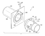
- the ground side 24 of disconnect valve 20 is described in connection with FIGS. 3-5 .
- the ground side connector 24 includes an inner (or first) sleeve 32 and an outer (or second) sleeve 34 .
- Sleeves 32 an 34 slide relative to one another. More specifically, inner sleeve 32 slides within outer sleeve 34 .
- the inner sleeve 32 is adapted to carry the flow media.
- a pinion gear 36 is rotatably mounted to inner sleeve 32 via an axle. Pinion 36 rides upon a rack 38 this is formed upon an axial slot 42 within outer sleeve 34 .
- Outer sleeve 34 further includes opposing handles 44 that allow an operator to slide outer sleeve 34 with respect to inner sleeve 32 .
- a peripheral flange 46 and an associated locking clip 48 are included on outer sleeve 34 and serve in locking flight side connector 22 to ground side connector 24 as noted hereinafter.
- butterfly valve 52 is mounted on the same axle as pinion gear 36 , such that rotation of gear 36 results in the rotation of valve 52 .
- gear 36 rotates.
- Rotation of gear 36 causes the rotation of butterfly valve 52 .
- valve 52 is rotated between opened and closed positions as gear travels between the ends of slot 42 .
- Butterfly valve 52 has a fully closed orientation ( FIG. 6 ), a partially opened orientation ( FIG. 7 ), and a fully opened orientation ( FIG. 8 ).
- butterfly valve 52 seals against the inner surface of the inner sleeve 32 via contact with an elastomeric seal installed about the periphery of valve 52 . This seal slides into a groove in butterfly valve 52 for easy replacement as required.
- the ground side connector 24 is normally held in the closed position by a torsion spring attached to the axle of butterfly valve 52 . This torsion holds the valve shut and also transmits force via the rack and pinion ( 38 and 36 ) to hold outer sleeve 34 in a contracted position ( FIG. 6 ). Operation of valve 20 begins with both connectors ( 22 and 24 ) disconnected and closed ( FIG. 6 ).
- Flight slide connector 22 is similar in many respects to ground side connector 24 .
- flight side connector 22 includes inner (or first) sleeve 54 and an outer or second sleeve 56 .
- Sleeves 54 and 56 slide relative to one another.
- the inner sleeve 54 of flight side connector 22 actually rides within a circumferential opening 58 within outer sleeve 56 (note FIGS. 7 and 8 ).
- the circumferential opening 58 divides sleeve 56 into outer and inner extents 56 ( a ) and 56 ( b ). This arrangement also permits inner sleeve 54 to slide back and forth within sleeve 56 with a fixed stroke length.
- Flight side connector 22 further includes a pinion gear 26 that is interconnected to inner extent 56 ( a ) of sleeve 56 . Furthermore, pinion gear 26 rides upon, and is rotated by, a rack 28 this is formed upon an axial slot 60 within inner sleeve 54 ( FIG. 10 ).
- inner sleeve 54 In the unattached position (i.e. with connectors 22 and 24 uncoupled), inner sleeve 54 is fully extended by a compression spring 62 that is positioned within the base of circumferential opening 58 . This force is transmitted to inner sleeve 54 and to the rack and pinion.
- FIG. 6 illustrates the position of inner sleeve 54 within opening 58 when spring 62 is in the unbiased state.
- Flight side connector 22 also includes an internal butterfly valve 64 that is mounted to the pinion gear 26 .
- valve 64 can have a closed orientation ( FIG. 6 ), a partially opened orientation ( FIG. 7 ), or a fully opened orientation ( FIG. 8 ). In the unattached orientation (note FIG. 6 ), the force of compression spring 62 keeps butterfly valve 64 in the fully closed orientation.
- Mating of connectors is achieved by an operator manually abutting the ground side connector 24 to the flight side connector 22 . Thereafter, the operator presses inwardly on handles 44 . As a result, the inner most sleeve 32 of ground connector 24 butts up against the inner extent 56 ( b ) of sleeve 56 of flight side connector 22 . Continued movement of handles 44 causes the outer sleeve 34 of ground connector 24 to enter opening 58 and engage the inner sleeve 54 . As outer sleeve 34 enters opening 58 , it slides over an o-ring seal 66 on the inner diameter of the outer extent 56 ( a ) of sleeve 56 .
- compression spring 62 causes inner sleeve 54 to return to its extended position, which, in turn, causes butterfly 64 to rotate shut.
- butterfly valve 64 achieves its fully closed orientation ( FIG. 6 ) prior to sleeve 34 being removed from opening 58 .
- Valve 64 also shuts prior to sleeve 34 losing contact with seal 66 .
- the fluid tight, sleeve-to-sleeve seal accomplished by o-ring 66 is maintained as valve 64 shuts during withdrawal.
- o-ring 66 is preferably positioned within a space, or gap, that is formed between the end of inner sleeve 54 and the distal end of opening 58 . This gap is present even with valve 64 in its closed state.
- outer sleeve 34 can be positioned within the gap to form a fluid tight seal between two halves ( 22 and 24 ) without inner sleeve 54 being engaged or valve 64 otherwise being opened. This ensures that an adequate seal is formed prior to the full fluid circuit being completed.
- a variety of mechanisms can be employed to lock the two halves ( 22 and 24 ) together. For example, as the mating surfaces of the ground side connector 24 contact the flight slide connector 22 , four circumferential and equally spaced ball and spring type detents engage a circular groove in the flight slide connector 22 . This engagement would serve to align and retain the two halves of the disconnect 20 together. Pushing on the ground connector 24 would cause these detents to engage. Conversely, pulling on the ground side connector 24 would cause the four detent balls to disengage.
- the ground side connector 24 includes locking clip 48 that fits into a slot within tang or flange 68 on flight side connector 22 ( FIGS. 6-8 ).
- a standard MS detent pin 72 can be inserted into clip 48 to lock it to flange 68 and, thereby, lock the connectors ( 22 and 24 ) together.
- an external clamshell connector can be used to lock the two halves together.
- the sleeves ( 22 and 24 ) and butterfly valves ( 52 and 64 ) are composed of aircraft grade aluminum tubing, for low weight and anodized for corrosion protection.
- the locking clip 48 for ground side connector 24 is also aluminum.
- Each rack and pinion/shaft assembly ( 26 , 28 , 36 and 38 ) is composed of a 300 series stainless steel, for corrosion protection and wear resistance and to otherwise meet the 12,000 cycle requirement, which is the standard for harsh environments.
- the compression and torsion springs are stainless steel COTS parts.
- the elastomeric seals are Ethylene Propylene Rubber which exhibits good wear resistance over a wide range of temperatures.
- the four detents are COTS ball-plunger assemblies, stainless steel.
- the clamshell locking ring is also COTS.
Abstract
Description
Claims (7)
Priority Applications (1)
| Application Number | Priority Date | Filing Date | Title |
|---|---|---|---|
| US12/486,508 US8322368B2 (en) | 2008-06-18 | 2009-06-17 | Self sealing disconnect valve |
Applications Claiming Priority (2)
| Application Number | Priority Date | Filing Date | Title |
|---|---|---|---|
| US7352308P | 2008-06-18 | 2008-06-18 | |
| US12/486,508 US8322368B2 (en) | 2008-06-18 | 2009-06-17 | Self sealing disconnect valve |
Publications (2)
| Publication Number | Publication Date |
|---|---|
| US20090314978A1 US20090314978A1 (en) | 2009-12-24 |
| US8322368B2 true US8322368B2 (en) | 2012-12-04 |
Family
ID=41430265
Family Applications (1)
| Application Number | Title | Priority Date | Filing Date |
|---|---|---|---|
| US12/486,508 Active 2031-02-03 US8322368B2 (en) | 2008-06-18 | 2009-06-17 | Self sealing disconnect valve |
Country Status (1)
| Country | Link |
|---|---|
| US (1) | US8322368B2 (en) |
Cited By (5)
| Publication number | Priority date | Publication date | Assignee | Title |
|---|---|---|---|---|
| US20120299291A1 (en) * | 2010-02-18 | 2012-11-29 | Takanobu Kamiya | Fluid joint |
| KR102090820B1 (en) * | 2018-11-28 | 2020-03-18 | 에스지솔루션(주) | breakway coupling |
| US20210404581A1 (en) * | 2016-04-18 | 2021-12-30 | Sartorius Stedim Biotech Gmbh | Connection device |
| US20220178482A1 (en) * | 2019-04-03 | 2022-06-09 | Sartorius Stedim Biotech Gmbh | Sterile connector for the sterile transfer of a liquid medium |
| US20230375118A1 (en) * | 2022-05-19 | 2023-11-23 | Ting-Jui Wang | Communicating structure |
Families Citing this family (1)
| Publication number | Priority date | Publication date | Assignee | Title |
|---|---|---|---|---|
| US11306828B2 (en) * | 2020-07-31 | 2022-04-19 | Quanta Computer Inc. | Quick-connector valve for liquid cooling |
Citations (6)
| Publication number | Priority date | Publication date | Assignee | Title |
|---|---|---|---|---|
| US4073472A (en) * | 1977-01-04 | 1978-02-14 | Koppers Company, Inc. | Articulated disc valve |
| US5305776A (en) * | 1990-02-06 | 1994-04-26 | Rosa Romano | Emergency shut-off device |
| US5351708A (en) * | 1993-12-13 | 1994-10-04 | Symetrics | Automatic fluid sealing mechanism for a conduit with a frangible connector |
| US5738143A (en) * | 1996-08-08 | 1998-04-14 | The United States Of America As Represented By The Secretary Of The Army | Butterfly actuated quick coupling connector valve |
| US20040094738A1 (en) * | 2001-03-22 | 2004-05-20 | Tomco Procucts, Inc., An Ohio Corporation | Universal safety coupler |
| US7131458B2 (en) * | 2003-10-22 | 2006-11-07 | Nitto Kohki Co., Ltd. | Pipe coupling including first and second coupling members |
-
2009
- 2009-06-17 US US12/486,508 patent/US8322368B2/en active Active
Patent Citations (6)
| Publication number | Priority date | Publication date | Assignee | Title |
|---|---|---|---|---|
| US4073472A (en) * | 1977-01-04 | 1978-02-14 | Koppers Company, Inc. | Articulated disc valve |
| US5305776A (en) * | 1990-02-06 | 1994-04-26 | Rosa Romano | Emergency shut-off device |
| US5351708A (en) * | 1993-12-13 | 1994-10-04 | Symetrics | Automatic fluid sealing mechanism for a conduit with a frangible connector |
| US5738143A (en) * | 1996-08-08 | 1998-04-14 | The United States Of America As Represented By The Secretary Of The Army | Butterfly actuated quick coupling connector valve |
| US20040094738A1 (en) * | 2001-03-22 | 2004-05-20 | Tomco Procucts, Inc., An Ohio Corporation | Universal safety coupler |
| US7131458B2 (en) * | 2003-10-22 | 2006-11-07 | Nitto Kohki Co., Ltd. | Pipe coupling including first and second coupling members |
Cited By (7)
| Publication number | Priority date | Publication date | Assignee | Title |
|---|---|---|---|---|
| US20120299291A1 (en) * | 2010-02-18 | 2012-11-29 | Takanobu Kamiya | Fluid joint |
| US9052048B2 (en) * | 2010-02-18 | 2015-06-09 | Mitsubishi Heavy Industries, Ltd. | Fluid joint |
| US20210404581A1 (en) * | 2016-04-18 | 2021-12-30 | Sartorius Stedim Biotech Gmbh | Connection device |
| US11668418B2 (en) * | 2016-04-18 | 2023-06-06 | Sartorius Stedim Biotech Gmbh | Connection device |
| KR102090820B1 (en) * | 2018-11-28 | 2020-03-18 | 에스지솔루션(주) | breakway coupling |
| US20220178482A1 (en) * | 2019-04-03 | 2022-06-09 | Sartorius Stedim Biotech Gmbh | Sterile connector for the sterile transfer of a liquid medium |
| US20230375118A1 (en) * | 2022-05-19 | 2023-11-23 | Ting-Jui Wang | Communicating structure |
Also Published As
| Publication number | Publication date |
|---|---|
| US20090314978A1 (en) | 2009-12-24 |
Similar Documents
| Publication | Publication Date | Title |
|---|---|---|
| US8322368B2 (en) | Self sealing disconnect valve | |
| US9874293B2 (en) | Fluid transfer device with quick-acting shutoff | |
| US9371949B2 (en) | Locking mechanism for unisex ball valve coupling | |
| US8931499B2 (en) | Ball and socket breakaway connector | |
| US2915325A (en) | Separable couplings | |
| US8720487B2 (en) | Grease delivery receiver and nozzle couplable without fluid pressure bleed-down and having pressurization lockout and flush face coupling | |
| US5099883A (en) | Low spill identical half coupling | |
| JPH0425594Y2 (en) | ||
| US9528648B2 (en) | Breakaway assembly with relief valve | |
| WO2016109485A2 (en) | Double piston effect lip seal seating assemblies | |
| US9851017B2 (en) | Locking mechanism for unisex ball valve coupling | |
| US10060564B2 (en) | Quick connect torque coupling with safety lock | |
| US20140326346A1 (en) | Coupling | |
| US8602457B2 (en) | Quick connect apparatus | |
| CN114576456A (en) | Bidirectional throttling connector | |
| JP6154703B2 (en) | Coupler | |
| US9534699B2 (en) | Lower effort quick-connect coupler | |
| US7677261B1 (en) | High flow, low mobile weight quick disconnect system | |
| CN216143346U (en) | Valve core and valve quick joint | |
| US4543992A (en) | Fluid coupling assembly | |
| CN219159597U (en) | Gas lock control ball valve | |
| CN217603586U (en) | Quick fluid sealing joint | |
| JPH026397B2 (en) | ||
| CA2657170A1 (en) | Articulating joint with injector port | |
| US10240702B2 (en) | Lower effort quick-connect coupler |
Legal Events
| Date | Code | Title | Description |
|---|---|---|---|
| AS | Assignment |
Owner name: CONAX FLORIDA CORPORATION, FLORIDA Free format text: ASSIGNMENT OF ASSIGNORS INTEREST;ASSIGNOR:ZENZ, ZAC D.;REEL/FRAME:023115/0870 Effective date: 20090810 |
|
| STCF | Information on status: patent grant |
Free format text: PATENTED CASE |
|
| AS | Assignment |
Owner name: CARLETON TECHNOLOGIES, INC., NEW YORK Free format text: ASSIGNMENT OF ASSIGNORS INTEREST;ASSIGNOR:CONAX FLORIDA CORPORATION;REEL/FRAME:031875/0855 Effective date: 20131119 |
|
| REMI | Maintenance fee reminder mailed | ||
| FPAY | Fee payment |
Year of fee payment: 4 |
|
| SULP | Surcharge for late payment | ||
| AS | Assignment |
Owner name: COBHAM MISSION SYSTEMS ORCHARD PARK INC., NEW YORK Free format text: CHANGE OF NAME;ASSIGNOR:CARLETON TECHNOLOGIES, INC.;REEL/FRAME:050397/0980 Effective date: 20190808 |
|
| MAFP | Maintenance fee payment |
Free format text: PAYMENT OF MAINTENANCE FEE, 8TH YEAR, LARGE ENTITY (ORIGINAL EVENT CODE: M1552); ENTITY STATUS OF PATENT OWNER: LARGE ENTITY Year of fee payment: 8 |
|
| AS | Assignment |
Owner name: WILMINGTON TRUST, NATIONAL ASSOCIATION, MINNESOTA Free format text: FIRST LIEN US INTELLECTUAL PROPERTY SECURITY AGREEMENT;ASSIGNORS:COBHAM MISSION SYSTEMS DAVENPORT AAR INC.;COBHAM MISSION SYSTEMS DAVENPORT LSS INC.;COBHAM MISSION SYSTEMS ORCHARD PARK INC.;AND OTHERS;REEL/FRAME:052945/0547 Effective date: 20200612 Owner name: WILMINGTON TRUST, NATIONAL ASSOCIATION, MINNESOTA Free format text: SECOND LIEN US INTELLECTUAL PROPERTY SECURITY AGREEMENT;ASSIGNORS:COBHAM MISSION SYSTEMS DAVENPORT AAR INC.;COBHAM MISSION SYSTEMS DAVENPORT LSS INC.;COBHAM MISSION SYSTEMS ORCHARD PARK INC.;AND OTHERS;REEL/FRAME:052945/0653 Effective date: 20200612 |
|
| AS | Assignment |
Owner name: COBHAM MISSION SYSTEMS DAVENPORT AAR INC., IOWA Free format text: PARTIAL RELEASE OF SECURITY INTEREST IN INTELLECTUAL PROPERTY;ASSIGNOR:WILMINGTON TRUST, NATIONAL ASSOCIATION, AS SECURITY AGENT;REEL/FRAME:056461/0677 Effective date: 20210601 Owner name: COBHAM MISSION SYSTEMS DAVENPORT LSS INC., IOWA Free format text: PARTIAL RELEASE OF SECURITY INTEREST IN INTELLECTUAL PROPERTY;ASSIGNOR:WILMINGTON TRUST, NATIONAL ASSOCIATION, AS SECURITY AGENT;REEL/FRAME:056461/0677 Effective date: 20210601 Owner name: COBHAM MISSION SYSTEMS ORCHARD PARK INC., IOWA Free format text: PARTIAL RELEASE OF SECURITY INTEREST IN INTELLECTUAL PROPERTY;ASSIGNOR:WILMINGTON TRUST, NATIONAL ASSOCIATION, AS SECURITY AGENT;REEL/FRAME:056461/0677 Effective date: 20210601 Owner name: COBHAM MISSION SYSTEMS DAVENPORT AAR INC., IOWA Free format text: PARTIAL RELEASE OF SECURITY INTEREST IN INTELLECTUAL PROPERTY;ASSIGNOR:WILMINGTON TRUST, NATIONAL ASSOCIATION, AS SECURITY AGENT;REEL/FRAME:056461/0689 Effective date: 20210601 Owner name: COBHAM MISSION SYSTEMS DAVENPORT LSS INC., IOWA Free format text: PARTIAL RELEASE OF SECURITY INTEREST IN INTELLECTUAL PROPERTY;ASSIGNOR:WILMINGTON TRUST, NATIONAL ASSOCIATION, AS SECURITY AGENT;REEL/FRAME:056461/0689 Effective date: 20210601 Owner name: COBHAM MISSION SYSTEMS ORCHARD PARK INC., IOWA Free format text: PARTIAL RELEASE OF SECURITY INTEREST IN INTELLECTUAL PROPERTY;ASSIGNOR:WILMINGTON TRUST, NATIONAL ASSOCIATION, AS SECURITY AGENT;REEL/FRAME:056461/0689 Effective date: 20210601 |