US8322112B2 - Nestable structural hollow body and related methods - Google Patents
Nestable structural hollow body and related methods Download PDFInfo
- Publication number
- US8322112B2 US8322112B2 US12/656,418 US65641810A US8322112B2 US 8322112 B2 US8322112 B2 US 8322112B2 US 65641810 A US65641810 A US 65641810A US 8322112 B2 US8322112 B2 US 8322112B2
- Authority
- US
- United States
- Prior art keywords
- hollow body
- section
- sections
- hollow
- structural support
- Prior art date
- Legal status (The legal status is an assumption and is not a legal conclusion. Google has not performed a legal analysis and makes no representation as to the accuracy of the status listed.)
- Active
Links
- 238000000034 method Methods 0.000 title claims description 17
- 230000007246 mechanism Effects 0.000 claims abstract description 14
- 239000000463 material Substances 0.000 claims description 12
- 239000004033 plastic Substances 0.000 description 7
- 238000010276 construction Methods 0.000 description 5
- 238000004519 manufacturing process Methods 0.000 description 5
- 239000007787 solid Substances 0.000 description 5
- 238000001746 injection moulding Methods 0.000 description 3
- 230000013011 mating Effects 0.000 description 3
- 230000035882 stress Effects 0.000 description 3
- 239000002184 metal Substances 0.000 description 2
- 229910052751 metal Inorganic materials 0.000 description 2
- 238000012986 modification Methods 0.000 description 2
- 230000004048 modification Effects 0.000 description 2
- 230000002093 peripheral effect Effects 0.000 description 2
- 238000013459 approach Methods 0.000 description 1
- 230000015572 biosynthetic process Effects 0.000 description 1
- 238000000071 blow moulding Methods 0.000 description 1
- 230000001010 compromised effect Effects 0.000 description 1
- 239000004035 construction material Substances 0.000 description 1
- 230000000694 effects Effects 0.000 description 1
- 230000006355 external stress Effects 0.000 description 1
- 238000010097 foam moulding Methods 0.000 description 1
- 238000002347 injection Methods 0.000 description 1
- 239000007924 injection Substances 0.000 description 1
- 238000005495 investment casting Methods 0.000 description 1
- 150000002739 metals Chemical class 0.000 description 1
- 239000002991 molded plastic Substances 0.000 description 1
- 238000000465 moulding Methods 0.000 description 1
- 230000003014 reinforcing effect Effects 0.000 description 1
- 229920005989 resin Polymers 0.000 description 1
- 239000011347 resin Substances 0.000 description 1
- 238000001175 rotational moulding Methods 0.000 description 1
- 238000007789 sealing Methods 0.000 description 1
- 238000000926 separation method Methods 0.000 description 1
- 238000003860 storage Methods 0.000 description 1
- 239000004616 structural foam Substances 0.000 description 1
- XLYOFNOQVPJJNP-UHFFFAOYSA-N water Substances O XLYOFNOQVPJJNP-UHFFFAOYSA-N 0.000 description 1
Images


Classifications
-
- E—FIXED CONSTRUCTIONS
- E04—BUILDING
- E04C—STRUCTURAL ELEMENTS; BUILDING MATERIALS
- E04C5/00—Reinforcing elements, e.g. for concrete; Auxiliary elements therefor
- E04C5/07—Reinforcing elements of material other than metal, e.g. of glass, of plastics, or not exclusively made of metal
-
- C—CHEMISTRY; METALLURGY
- C04—CEMENTS; CONCRETE; ARTIFICIAL STONE; CERAMICS; REFRACTORIES
- C04B—LIME, MAGNESIA; SLAG; CEMENTS; COMPOSITIONS THEREOF, e.g. MORTARS, CONCRETE OR LIKE BUILDING MATERIALS; ARTIFICIAL STONE; CERAMICS; REFRACTORIES; TREATMENT OF NATURAL STONE
- C04B38/00—Porous mortars, concrete, artificial stone or ceramic ware; Preparation thereof
- C04B38/08—Porous mortars, concrete, artificial stone or ceramic ware; Preparation thereof by adding porous substances
-
- E—FIXED CONSTRUCTIONS
- E04—BUILDING
- E04B—GENERAL BUILDING CONSTRUCTIONS; WALLS, e.g. PARTITIONS; ROOFS; FLOORS; CEILINGS; INSULATION OR OTHER PROTECTION OF BUILDINGS
- E04B5/00—Floors; Floor construction with regard to insulation; Connections specially adapted therefor
- E04B5/16—Load-carrying floor structures wholly or partly cast or similarly formed in situ
- E04B5/32—Floor structures wholly cast in situ with or without form units or reinforcements
- E04B5/326—Floor structures wholly cast in situ with or without form units or reinforcements with hollow filling elements
- E04B5/328—Floor structures wholly cast in situ with or without form units or reinforcements with hollow filling elements the filling elements being spherical
Definitions
- the invention relates generally to structural components and related methods, and more specifically to a nestable spherical hollow body that is convenient to use and assemble at least for structural support and/or creating internal cavities in concrete or similar applications.
- Prestressed, prefabricated concrete elements with extended cross sections and internal hollow cylindrical cavities have been used to reduce the weight “problems”, but they typically only span in a “single” direction. In other words, they are typically relatively long and narrow concrete beams with one or more web elements extending significantly below the concrete “deck.”
- Alternative approaches have included placing lightweight balls within the concrete as it is poured (for example, see DE 2,116,479) or similarly positioning hollow spheres within a mesh assembly in the concrete (for example, see U.S. Pat. No. 5,396,747, issued to Breuning in 1995).
- BubbleDeck currently produces a pre-fabricated solid concrete slab structure having plastic balls embedded in concrete, to reduce the slab's weight. According to BubbleDeck, the pre-fabricated concrete slab can reduce construction material weight by up to fifty percent (50%).
- the BubbleDeck plastic balls are hollow, spherical shapes (similar to ping pong balls), and are of a solid fixed single piece construction. That single piece hollow body construction apparently has a generally uniform wall thickness sufficient to withstand the stress imposed by the surrounding concrete material, but that solid fixed single piece construction limits at least the shipping and handling characteristics of the inserts (balls) prior to use, and can also affect the stress handling capacity of the plastic balls.
- the invention is directed to a nestable hollow body that, among other things, is useful for at least structural support and/or creating internal cavities for an improved strength-to-weight ratio in a variety of concrete or other structures.
- the present invention preferably provides a single connected element whose parts can be easily moved (via hinges or otherwise) from an “open” or nestable position into a “closed” or assembled position.
- the invention provides for, among other things, nestabilty in a hollow body, and provides for space saving and efficient methods of manufacturing, handling, storing, transporting, and/or assembling the hollow bodies.
- the invention further facilitates additional structural support within the hollow body itself, to increase the load bearing capacity of the hollow body when subjected to external forces such as those commonly imposed on it by concrete or when otherwise used for its intended purposes.
- the device is preferably a multi-section hollow body having: (1) a structural support network disposed within or formed in its interior; (2) a hinge mechanism to keep the sections connected to each other prior to assembly and to permit repositioning (or “closing”) of the sections into a final desired configuration prior to their use; and (3) at least one latch mechanism to help hold the sections in that final desired configuration prior to their use.
- an integral hinge preferably permits a top or first section of the hollow body and a bottom or second section of the hollow body to be (1) fabricated in an opened or an extended state (which permits stacking or nesting of a plurality of hollow bodies on top of each other prior to their eventual use), and then (2) moved to a closed or an assembled state to permit use of the hollow body for its intended purposes.
- FIG. 1 is a perspective view showing a multi-portion hollow body in a closed or assembled state, in accordance with one embodiment of the present invention.
- FIG. 2 is similar to FIG. 1 , but shows the hollow body in a slightly open position.
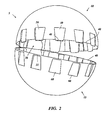
- FIG. 3 is a perspective view looking down into the interior of the body of FIG. 2 after it has been further opened, and illustrates an embodiment of a structural support network disposed within each of the sections of the body.
- FIG. 4( a ) is a side perspective view of a plurality of the bodies of FIG. 3 , inverted and stacked and nested with each other.
- FIG. 4( b ) is a sectional view of the stacked and nested bodies of FIG. 4( a ), with the section being taken along the widest portion of the bodies and generally parallel to the plane of the paper on which FIG. 4( a ) is shown.
- FIG. 5 is similar to FIG. 3 , but shows a close-up view of the central interconnecting portion of the body, illustrating one embodiment of a hinge that can be used in the hollow body of FIG. 1 .
- FIG. 6 is similar to FIG. 2 , but shows a close-up view of one embodiment of a latch mechanism that can be used in the hollow body of FIG. 1 .
- FIG. 7( a ) is similar to FIG. 6 , but shows the latch mechanism in a closed or secured position, such as the position shown in FIG. 1 .
- FIG. 7( b ) is similar to FIG. 7( a ), but shows a partially sectional perspective view of the latch mechanism, with the section taken in a generally vertical plane through FIG. 7( a ).
- fabrication processes include die cast, investment casting, sheet metal stamping, single/twin sheet thermo-form, blow-molding, rotational molding, injection molding, gas assist, water assist, web molding, structural foam molding, and many other existing and new processes that may come into being.
- Materials are not limited in anyway and could extend from metals to resins of all types.
- a preferred material is plastic, and a preferred method of fabrication is by injection molding.
- the device described herein may generally be used for at least structural support and/or creating internal cavities for improved strength-to-weight ratio in a variety of structures.
- the structural hollow bodies described herein are typically intended to be embedded in concrete or some other material for the purpose of eliminating the concrete or some other material that has weight but no carrying effect.
- Persons of ordinary skill in the art will understand that although the aforementioned application may be a preferred use, the structural hollow bodies described herein may be used in any number of other applications.
- the device is preferably a hollow body 5 having: (1) a top/first section 10 and a bottom/second section 15 of substantially the same size and shape; (2) a structural support network 20 disposed within the hollow body 5 to increase the load bearing capacity of the hollow body 5 when subjected to external forces; (3) at least one latch mechanism 25 positioned along the periphery 40 of the hollow body 5 ; and (4) a corresponding hinge 30 positioned along the periphery 40 of the hollow body 5 so as to permit repositioning of the top section 10 of the hollow body 5 and the bottom section 15 of the hollow body 5 from an opened state, to permit nesting of a plurality of such hollow bodies 5 on top of each other, to a closed state to permit use of the hollow body 5 for its intended purposes.
- Persons of ordinary skill in the art will understand that the orientation of “top” or “bottom” used herein is for convenience only, and that the specific orientation of the body within a particular application can be any direction.
- top section 10 and bottom section 15 are secured to each other along the periphery 40 of top section 10 and bottom section 15 to form a sidewall of hollow body 5 that encloses an interior of hollow body 5 .
- the geometric shape of the device 5 described herein is preferably spherical, having a top section 10 and a bottom section 15 of substantially the same size and shape (i.e., half spheres).
- the device 5 can be of virtually any size and shape. Such shapes may include a square, triangle, hexagon, geodesic dome/sphere, or other shape.
- the wall thickness of the hollow body 5 and/or structural support network 20 may vary and will typically depend on the device's intended use or application.
- the preferred hinge 30 (connecting the top section to the bottom section) is formed as part of an area of reduced thickness of plastic 35 along the periphery 40 between the top section 10 and the bottom section 15 of the hollow body 5 .
- the hinge can be a “living hinge” formed of the same plastic as the rest of the body.
- the hollow bodies 5 When used for their intended purposes (i.e., for structural support and/or creating internal cavities for improved strength-to-weight ratio in a variety of structures), the hollow bodies 5 preferably are in a closed or assembled state, as shown in FIG. 1 . No further repositioning of the top section 10 of the hollow body 5 relative to the bottom section 15 of the hollow body 5 is needed. While other more durable hinge types may be utilized, the hinge 30 is intended for a single use application so its durability is relatively less important than its lightweight and cost effective production.
- the hinge 30 permits the hollow bodies 5 to be shipped or transported from the manufacturer to an end user in an opened or an extended state to facilitate efficient stacking and/or nesting of a plurality of such hollow bodies 5 on top of each other, thereby increasing the number of hollow bodies 5 capable of being contained in a given space (as compared to the number of assembled hollow bodies (or fixed, single piece ping-pong ball type bodies) capable of being contained in the same space).
- the hollow body 5 preferably includes at least one latch mechanism 25 , and preferably includes a plurality of such latch mechanisms 25 .
- the latch mechanism 25 preferably includes an enlarged head or male portion 45 formed on the periphery 40 and protruding from a first recessed portion 50 formed on one of the top section 10 or a bottom section 15 of the hollow body 5 , and a correspondingly shaped cavity or female portion 55 formed on the periphery 40 as part of a second recessed portion 60 on the other one of the top section 10 or the bottom section 15 of the hollow body 5 for receiving or mating with the head 45 to join, close, or seal the top and bottom sections 10 , 15 along the peripheral 40 (mating area between the top section 10 and bottom section 15 of the hollow body) when the hollow body 5 is in the closed or assembled state.
- the head 45 preferably is constructed with an enlarged protrusion 65 such that, as the head 45 makes initial contact with the cavity 55 , the head 45 moves in a direction away from the periphery 40 of the hollow body 5 so as to be received into the cavity 55 .
- material memory and/or compressive hoop stress causes the head 45 to move back out into its original position, securing the protruding portion 65 of the head 45 firmly against a lip 70 of the cavity 55 , and securing the top section 10 of the hollow body 5 to the bottom section 15 of the hollow body 5 along the peripheral edges 40 .
- the latch 25 is intended for a single use application.
- the hollow body 5 once secured in the closed or assembled state the hollow body 5 is ready for its intended use. No further repositioning of the top section 10 of the hollow body 5 relative to the bottom section 15 of the hollow body 5 is needed.
- a plurality of latch mechanisms 25 are preferably provided and used, to increase the integrity of the hollow body 5 in its closed or “sealed” state (i.e., to maximize accurate engagement and minimize the risk of collapse or deformation of the hollow body 5 due to external stress resulting in partial or total separation of the top section 10 from the bottom section 15 , or other “failure” of the body's void-making purpose in certain applications).
- any suitable latch may be utilized within the scope of the invention.
- the sealing or further securing of the top section 10 of the hollow body 5 to the bottom section 15 of the hollow body 5 along the periphery 40 may be further aided or facilitated in any number of ways, including the use of a mating tongue and groove structure and/or gasket member along the periphery 40 , for example.
- the hinge 30 and latch(es) 25 preferably are constructed such that in the closed or assembled state the hinge 30 and latch(es) 25 do not protrude beyond the designated outside diameter of the hollow body 5 .
- each of the hinge 30 and latch(es) 25 are formed on a recessed portion 50 , 60 of the top section 10 of the hollow body 5 and the bottom section 15 of the hollow body 5 . Accordingly, as shown in FIG.
- each recessed portion 50 , 60 is sloped (as indicated by reference “s”) such that the hinge 30 and latch(es) 25 formed on the periphery 40 as part of each recess 50 , 60 are inset a distance (as indicated by reference “i”) from the perimeter 40 of the hollow body 5 .
- such an inset “i” configuration of the hinge 30 and latch(es) 25 provides a generally smooth outer periphery 40 or profile of the hollow body 4 for purposes of efficient and stable stacking or nesting of a plurality of such hollow bodies 5 on top of each other in the opened or extended state as shown in FIGS. 4( a )-( b ).
- each of the top section 10 and the bottom section 15 of the hollow body 5 preferably includes a structural support network 20 (or web or rib(s)) formed on or disposed in or operatively affixed to the body section or sections.
- the structural support network 20 can increase the load bearing capacity of the hollow body 5 when subjected to the external forces commonly imposed on it, when used for at least structural support and/or to create internal cavities in a variety of structures.
- the structural support network 20 disposed within the hollow body 5 may be considered as somewhat of a compromise between a hollow body 5 without such a structural support 20 and a completely solid hollow body.
- the structural support network 20 permits a greater load bearing capacity than a hollow body 5 without such a structural support network 20 , but at a reduced weight when compared to a completely solid body.
- the reinforcing ribs or structural support network 20 includes a concentric ring 75 positioned generally near a central or bottom portion 80 of each of the top section 10 and the bottom section 15 of the hollow body 5 .
- the concentric ring 75 is distal from the periphery opening 40 of the hollow body 5 .
- a plurality of equally spaced (or other pattern of) support arms 85 radiate outward from the concentric ring 75 toward the periphery 40 of each of the top section 10 and the bottom section 15 to add structural stability to the hollow body sidewall.
- a hollow body structural support network 20 (a concentric ring 75 and one or more of the associated support arms 85 ) intended to withstand the force imposed on a hollow body 5 buried or encased in concrete may be constructed considerably thicker and/or larger in some aspect as compared to a hollow body structural support network 20 that is intended to be buried or encased in some lighter material.
Landscapes
- Engineering & Computer Science (AREA)
- Architecture (AREA)
- Chemical & Material Sciences (AREA)
- Structural Engineering (AREA)
- Ceramic Engineering (AREA)
- Civil Engineering (AREA)
- Electromagnetism (AREA)
- Physics & Mathematics (AREA)
- Materials Engineering (AREA)
- Organic Chemistry (AREA)
- Moulds, Cores, Or Mandrels (AREA)
- Moulds For Moulding Plastics Or The Like (AREA)
- Laminated Bodies (AREA)
Abstract
Description
Claims (8)
Priority Applications (2)
| Application Number | Priority Date | Filing Date | Title |
|---|---|---|---|
| US12/656,418 US8322112B2 (en) | 2006-02-28 | 2010-01-28 | Nestable structural hollow body and related methods |
| US29/377,706 USD639449S1 (en) | 2006-02-28 | 2010-10-25 | Nestable structural hollow body |
Applications Claiming Priority (2)
| Application Number | Priority Date | Filing Date | Title |
|---|---|---|---|
| US11/364,288 US20070199254A1 (en) | 2006-02-28 | 2006-02-28 | Nestable structural hollow body and related methods |
| US12/656,418 US8322112B2 (en) | 2006-02-28 | 2010-01-28 | Nestable structural hollow body and related methods |
Related Parent Applications (1)
| Application Number | Title | Priority Date | Filing Date |
|---|---|---|---|
| US11/364,288 Division US20070199254A1 (en) | 2006-02-28 | 2006-02-28 | Nestable structural hollow body and related methods |
Related Child Applications (1)
| Application Number | Title | Priority Date | Filing Date |
|---|---|---|---|
| US29/377,706 Continuation-In-Part USD639449S1 (en) | 2006-02-28 | 2010-10-25 | Nestable structural hollow body |
Publications (2)
| Publication Number | Publication Date |
|---|---|
| US20100132290A1 US20100132290A1 (en) | 2010-06-03 |
| US8322112B2 true US8322112B2 (en) | 2012-12-04 |
Family
ID=38442702
Family Applications (2)
| Application Number | Title | Priority Date | Filing Date |
|---|---|---|---|
| US11/364,288 Abandoned US20070199254A1 (en) | 2006-02-28 | 2006-02-28 | Nestable structural hollow body and related methods |
| US12/656,418 Active US8322112B2 (en) | 2006-02-28 | 2010-01-28 | Nestable structural hollow body and related methods |
Family Applications Before (1)
| Application Number | Title | Priority Date | Filing Date |
|---|---|---|---|
| US11/364,288 Abandoned US20070199254A1 (en) | 2006-02-28 | 2006-02-28 | Nestable structural hollow body and related methods |
Country Status (3)
| Country | Link |
|---|---|
| US (2) | US20070199254A1 (en) |
| CA (1) | CA2677334C (en) |
| WO (1) | WO2007100871A2 (en) |
Cited By (11)
| Publication number | Priority date | Publication date | Assignee | Title |
|---|---|---|---|---|
| US20120311959A1 (en) * | 2009-12-21 | 2012-12-13 | Cobiax Technologies Ag | Half shell element for the production of a hollow body |
| US20130160385A1 (en) * | 2010-06-28 | 2013-06-27 | Alberto Alarcon Garcia | Lightweight Slab Or Similar Structural Element Which Can Receive Equipment That Is Accessible And That Can Extend Through The Slab |
| USD686875S1 (en) | 2010-09-10 | 2013-07-30 | Seana L. Montgomery | Bowl with utensil retention feature |
| US8695838B1 (en) | 2012-06-06 | 2014-04-15 | Seana L. Montgomery | Bowl with utensil holder |
| USD748078S1 (en) * | 2013-10-25 | 2016-01-26 | Devialet | Remote control |
| US10179675B2 (en) * | 2013-12-19 | 2019-01-15 | Velmont & Company, Inc. | Dispensing container with interior access |
| US10675217B2 (en) | 2017-03-10 | 2020-06-09 | Corr-Jensen Inc. | Spherical pill container with domed lid |
| USD889972S1 (en) | 2017-04-20 | 2020-07-14 | Corr-Jensen Inc. | Spherical bottle |
| USD894754S1 (en) | 2017-04-20 | 2020-09-01 | Corr-Jensen Inc. | Packaging |
| AU2018429169B2 (en) * | 2018-06-26 | 2021-03-04 | Velmont & Company, Inc. | Dispensing container with interior access |
| US20220282480A1 (en) * | 2021-03-08 | 2022-09-08 | Plascon Plastics Corporation | Lattice of hollow bodies with reinforcement member supports |
Families Citing this family (12)
| Publication number | Priority date | Publication date | Assignee | Title |
|---|---|---|---|---|
| ITTO20060879A1 (en) * | 2006-12-12 | 2008-06-13 | Pontarolo Engineering Spa | UNIT FOR CONSTRUCTION OF PODS INSOLES. |
| US20130257473A1 (en) * | 2008-07-16 | 2013-10-03 | Lockheed Martin Corporation | Long-life power source, long-life embedded structure sensor, remote long-life fluid measurement and analysis system, long-life off-grid enclosed space proximity change detector, surface-mount encryption device with volatile long-life key storage and volume intrusion response, and portable encrypted data storage with volatile long-life key storage and volume intrusion response |
| WO2014015375A1 (en) * | 2012-07-23 | 2014-01-30 | Novaplas Pty Ltd | Collapsible void former |
| CZ306962B6 (en) * | 2012-07-30 | 2017-10-18 | Vysoké Učení Technické V Brně | A collecting vessel designed for the system of pneumatic waste transport pipeline |
| JP5992374B2 (en) * | 2013-08-02 | 2016-09-14 | 株式会社バンダイ | Container for goods |
| US9103119B2 (en) * | 2013-12-13 | 2015-08-11 | Joel Foderberg | Tie system for insulated concrete panels |
| US9493946B2 (en) | 2013-12-13 | 2016-11-15 | Iconx, Llc | Tie system for insulated concrete panels |
| US9315983B1 (en) | 2015-06-15 | 2016-04-19 | Canadian Telescopes Inc. | Modular observatory and an unassembled kit thereof |
| EP3433450B1 (en) | 2016-05-11 | 2021-10-20 | Joel Foderberg | System for insulated concrete composite wall panels |
| JP2016196334A (en) * | 2016-08-16 | 2016-11-24 | 株式会社バンダイ | Article storage container |
| WO2021019315A1 (en) * | 2019-07-31 | 2021-02-04 | Khaled Azzam | A novel set of concave framework to be utilised as light concrete slabs |
| ES1243071Y (en) * | 2020-01-08 | 2020-08-27 | Valls Jose Carbonell | FERRALLA PROTECTION PIECE |
Citations (18)
| Publication number | Priority date | Publication date | Assignee | Title |
|---|---|---|---|---|
| US1085862A (en) * | 1912-11-25 | 1914-02-03 | Ernest A Herzberg | Floor structure. |
| US2792164A (en) * | 1951-08-10 | 1957-05-14 | Cauffiel John | Preformed structural units |
| US3043354A (en) * | 1960-07-15 | 1962-07-10 | Edmund J Fitzgerald | Molded plastic container |
| US3543458A (en) * | 1967-12-27 | 1970-12-01 | Kenneth E Guritz | Monolithic floor structure with air passages |
| DE2116479A1 (en) | 1970-04-27 | 1971-12-30 | Nyffeler, Hans, Utzenstorf, Bern (Schweiz) | Core body for concrete slabs |
| US4060954A (en) * | 1972-11-03 | 1977-12-06 | Liuzza James J | Bar chair for reinforcing rods |
| US5072911A (en) * | 1990-07-03 | 1991-12-17 | The Logsdon Foundation | Barrier mold for forming openings in concrete structures |
| US5396747A (en) * | 1990-10-01 | 1995-03-14 | Breuning; Jorgen I. | Plane hollow reinforced concrete floors with two-dimensional structure |
| US5797230A (en) * | 1994-03-10 | 1998-08-25 | Lassen; Jorgen | Element for use in making a reinforced concrete structure with cavities, filler body for making such an element, and method of making a reinforced concrete structure with cavities |
| US5893252A (en) * | 1996-05-16 | 1999-04-13 | Hardy Construction Technology, Llc | System for affixing rebar lattice to receive concrete |
| US6050438A (en) * | 1996-06-27 | 2000-04-18 | Parkway Machine Corporation | Spherical dispensing capsule |
| US6325211B1 (en) | 2000-06-02 | 2001-12-04 | Lori Greiner | Decorative container and method for decorating a container |
| US6840018B2 (en) * | 2002-12-19 | 2005-01-11 | Fukuvi Usa, Inc. | Elongate bodies for use in pre-cast panel forming systems |
| US20050284071A1 (en) * | 2002-09-23 | 2005-12-29 | Ewald Houben | Construction element and method for manufacturing it |
| US20070214740A1 (en) * | 2003-12-23 | 2007-09-20 | The Australian Steel Company (Operations) Pty Ltd | Cavity Former |
| US7451580B2 (en) * | 2004-03-26 | 2008-11-18 | Mmi Management Services Lp | Rebar chair and supporting plate |
| US7540121B2 (en) * | 2004-08-13 | 2009-06-02 | Bam Ag | Steel-concrete hollow bodied slab or ceiling |
| USD639449S1 (en) * | 2006-02-28 | 2011-06-07 | Ropak Corporation | Nestable structural hollow body |
-
2006
- 2006-02-28 US US11/364,288 patent/US20070199254A1/en not_active Abandoned
-
2007
- 2007-02-28 WO PCT/US2007/005197 patent/WO2007100871A2/en active Application Filing
- 2007-02-28 CA CA2677334A patent/CA2677334C/en active Active
-
2010
- 2010-01-28 US US12/656,418 patent/US8322112B2/en active Active
Patent Citations (19)
| Publication number | Priority date | Publication date | Assignee | Title |
|---|---|---|---|---|
| US1085862A (en) * | 1912-11-25 | 1914-02-03 | Ernest A Herzberg | Floor structure. |
| US2792164A (en) * | 1951-08-10 | 1957-05-14 | Cauffiel John | Preformed structural units |
| US3043354A (en) * | 1960-07-15 | 1962-07-10 | Edmund J Fitzgerald | Molded plastic container |
| US3543458A (en) * | 1967-12-27 | 1970-12-01 | Kenneth E Guritz | Monolithic floor structure with air passages |
| DE2116479A1 (en) | 1970-04-27 | 1971-12-30 | Nyffeler, Hans, Utzenstorf, Bern (Schweiz) | Core body for concrete slabs |
| US4060954A (en) * | 1972-11-03 | 1977-12-06 | Liuzza James J | Bar chair for reinforcing rods |
| US5072911A (en) * | 1990-07-03 | 1991-12-17 | The Logsdon Foundation | Barrier mold for forming openings in concrete structures |
| US5396747A (en) * | 1990-10-01 | 1995-03-14 | Breuning; Jorgen I. | Plane hollow reinforced concrete floors with two-dimensional structure |
| US5797230A (en) * | 1994-03-10 | 1998-08-25 | Lassen; Jorgen | Element for use in making a reinforced concrete structure with cavities, filler body for making such an element, and method of making a reinforced concrete structure with cavities |
| US5893252A (en) * | 1996-05-16 | 1999-04-13 | Hardy Construction Technology, Llc | System for affixing rebar lattice to receive concrete |
| US6050438A (en) * | 1996-06-27 | 2000-04-18 | Parkway Machine Corporation | Spherical dispensing capsule |
| US6325211B1 (en) | 2000-06-02 | 2001-12-04 | Lori Greiner | Decorative container and method for decorating a container |
| US20050284071A1 (en) * | 2002-09-23 | 2005-12-29 | Ewald Houben | Construction element and method for manufacturing it |
| US7685789B2 (en) * | 2002-09-23 | 2010-03-30 | Gecoleng Aktiengesellschaft | Construction element and method for manufacturing it |
| US6840018B2 (en) * | 2002-12-19 | 2005-01-11 | Fukuvi Usa, Inc. | Elongate bodies for use in pre-cast panel forming systems |
| US20070214740A1 (en) * | 2003-12-23 | 2007-09-20 | The Australian Steel Company (Operations) Pty Ltd | Cavity Former |
| US7451580B2 (en) * | 2004-03-26 | 2008-11-18 | Mmi Management Services Lp | Rebar chair and supporting plate |
| US7540121B2 (en) * | 2004-08-13 | 2009-06-02 | Bam Ag | Steel-concrete hollow bodied slab or ceiling |
| USD639449S1 (en) * | 2006-02-28 | 2011-06-07 | Ropak Corporation | Nestable structural hollow body |
Non-Patent Citations (1)
| Title |
|---|
| Bubbledeck Flyer, http://www.bbdna.com/about.htm, Feb. 28, 2006. |
Cited By (15)
| Publication number | Priority date | Publication date | Assignee | Title |
|---|---|---|---|---|
| US9038352B2 (en) * | 2009-12-21 | 2015-05-26 | Cobiax Technologies Ag | Half shell element for the production of a hollow body |
| US20120311959A1 (en) * | 2009-12-21 | 2012-12-13 | Cobiax Technologies Ag | Half shell element for the production of a hollow body |
| US8943771B2 (en) * | 2010-06-28 | 2015-02-03 | Alberto Alarcon Garcia | Lightweight slab or similar structural element which can receive equipment that is accessible and that can extend through the slab |
| US20130160385A1 (en) * | 2010-06-28 | 2013-06-27 | Alberto Alarcon Garcia | Lightweight Slab Or Similar Structural Element Which Can Receive Equipment That Is Accessible And That Can Extend Through The Slab |
| USD688516S1 (en) | 2010-09-10 | 2013-08-27 | Seana L. Montgomery | Bowl with utensil retention feature |
| USD686875S1 (en) | 2010-09-10 | 2013-07-30 | Seana L. Montgomery | Bowl with utensil retention feature |
| US8695838B1 (en) | 2012-06-06 | 2014-04-15 | Seana L. Montgomery | Bowl with utensil holder |
| USD748078S1 (en) * | 2013-10-25 | 2016-01-26 | Devialet | Remote control |
| US10179675B2 (en) * | 2013-12-19 | 2019-01-15 | Velmont & Company, Inc. | Dispensing container with interior access |
| US10675217B2 (en) | 2017-03-10 | 2020-06-09 | Corr-Jensen Inc. | Spherical pill container with domed lid |
| USD889972S1 (en) | 2017-04-20 | 2020-07-14 | Corr-Jensen Inc. | Spherical bottle |
| USD894754S1 (en) | 2017-04-20 | 2020-09-01 | Corr-Jensen Inc. | Packaging |
| AU2018429169B2 (en) * | 2018-06-26 | 2021-03-04 | Velmont & Company, Inc. | Dispensing container with interior access |
| US20220282480A1 (en) * | 2021-03-08 | 2022-09-08 | Plascon Plastics Corporation | Lattice of hollow bodies with reinforcement member supports |
| US11566423B2 (en) * | 2021-03-08 | 2023-01-31 | Plascon Plastics Corporation | Lattice of hollow bodies with reinforcement member supports |
Also Published As
| Publication number | Publication date |
|---|---|
| WO2007100871A3 (en) | 2008-10-30 |
| WO2007100871A2 (en) | 2007-09-07 |
| US20100132290A1 (en) | 2010-06-03 |
| CA2677334A1 (en) | 2007-09-07 |
| US20070199254A1 (en) | 2007-08-30 |
| CA2677334C (en) | 2014-04-08 |
Similar Documents
| Publication | Publication Date | Title |
|---|---|---|
| US8322112B2 (en) | Nestable structural hollow body and related methods | |
| US8070005B1 (en) | Corrugated septic tank with strengthening features | |
| CA2401060C (en) | Vehicle body frame hollow member | |
| WO2000008273A3 (en) | Hexagon tile with equilateral reinforcement | |
| US7740149B2 (en) | Container sidewall strengthening apparatus and methods | |
| US5245733A (en) | Combination burial vault/casket | |
| US4031685A (en) | Reinforcing cage construction | |
| CA2454069A1 (en) | Structure of pile head joint portion and pile head fitting tubular body | |
| US20070289979A1 (en) | Double-wall plastic produce container having ventilation holes therein, and mold for the manufacture thereof | |
| KR101909351B1 (en) | Fabricated type hollow body for hollow core slab | |
| JP4156868B2 (en) | Top lid | |
| WO2019148300A1 (en) | Lattice of hollow bodies for use in the manufacture of reinforced concrete floor slabs | |
| US6467646B2 (en) | Box-shaped container of synthetic resin material | |
| CN110524686B (en) | Die for forming variable-section piles | |
| KR100924745B1 (en) | Water tank having a function of reinforcement by prestressed concrete steel wire | |
| WO2014015375A1 (en) | Collapsible void former | |
| JP2005320714A (en) | Knockdown hollow die embedded body for concrete slab and its continuously arranged body | |
| CN218787274U (en) | Rubber bushing with lightweight structure | |
| US20220282480A1 (en) | Lattice of hollow bodies with reinforcement member supports | |
| US20240246473A1 (en) | Fluid baffle for a tank | |
| CN221702870U (en) | Rib-sealing die box | |
| CN212666339U (en) | Be used for prefabricated cable cross well wall of a well mould | |
| CN213014921U (en) | Thin-wall square box | |
| CN203403410U (en) | Mold for manufacturing pile shoe of concrete pipe pile with interior round and exterior square | |
| JPH0219427Y2 (en) |
Legal Events
| Date | Code | Title | Description |
|---|---|---|---|
| AS | Assignment |
Owner name: ROPAK CORPORATION,CALIFORNIA Free format text: ASSIGNMENT OF ASSIGNORS INTEREST;ASSIGNOR:LUBURIC, FRANO;REEL/FRAME:023930/0712 Effective date: 20070911 Owner name: ROPAK CORPORATION, CALIFORNIA Free format text: ASSIGNMENT OF ASSIGNORS INTEREST;ASSIGNOR:LUBURIC, FRANO;REEL/FRAME:023930/0712 Effective date: 20070911 |
|
| STCF | Information on status: patent grant |
Free format text: PATENTED CASE |
|
| AS | Assignment |
Owner name: DEUTSCHE BANK TRUST COMPANY AMERICAS, AS COLLATERA Free format text: SECURITY AGREEMENT;ASSIGNOR:ROPAK CORPORATION;REEL/FRAME:029677/0360 Effective date: 20130118 |
|
| AS | Assignment |
Owner name: BANK OF AMERICA, N.A., AS COLLATERAL AGENT, GEORGI Free format text: SECURITY AGREEMENT;ASSIGNOR:ROPAK CORPORATION;REEL/FRAME:029684/0938 Effective date: 20130118 |
|
| AS | Assignment |
Owner name: ROPAK CORPORATION, GEORGIA Free format text: RELEASE OF SECURITY INTEREST;ASSIGNOR:DEUTSCHE BANK TRUST COMPANY AMERICAS;REEL/FRAME:033544/0302 Effective date: 20140814 |
|
| AS | Assignment |
Owner name: BANK OF AMERICA, N.A., AS COLLATERAL AGENT, NEW YO Free format text: SECURITY INTEREST;ASSIGNORS:BWAY CORPORATION;NORTH AMERICA PACKAGING CORPORATION;PLASTICAN, INC.;AND OTHERS;REEL/FRAME:033549/0357 Effective date: 20140814 |
|
| FEPP | Fee payment procedure |
Free format text: PAYOR NUMBER ASSIGNED (ORIGINAL EVENT CODE: ASPN); ENTITY STATUS OF PATENT OWNER: LARGE ENTITY |
|
| FPAY | Fee payment |
Year of fee payment: 4 |
|
| AS | Assignment |
Owner name: BANK OF AMERICA, N.A., AS COLLATERAL AGENT, NORTH Free format text: TERM LOAN SECURITY AGREEMENT;ASSIGNORS:BWAY CORPORATION;NORTH AMERICA PACKAGING CORPORATION;PLASTICAN, INC.;AND OTHERS;REEL/FRAME:042142/0644 Effective date: 20170403 Owner name: BWAY CORPORATION, GEORGIA Free format text: RELEASE BY SECURED PARTY;ASSIGNOR:BANK OF AMERICA, N.A.;REEL/FRAME:042142/0551 Effective date: 20170403 Owner name: NORTH AMERICA PACKAGING CORPORATION, GEORGIA Free format text: RELEASE BY SECURED PARTY;ASSIGNOR:BANK OF AMERICA, N.A.;REEL/FRAME:042142/0551 Effective date: 20170403 Owner name: ROPAK CORPORATION, GEORGIA Free format text: RELEASE BY SECURED PARTY;ASSIGNOR:BANK OF AMERICA, N.A.;REEL/FRAME:042142/0551 Effective date: 20170403 Owner name: PLASTICAN, INC., GEORGIA Free format text: RELEASE BY SECURED PARTY;ASSIGNOR:BANK OF AMERICA, N.A.;REEL/FRAME:042142/0551 Effective date: 20170403 |
|
| AS | Assignment |
Owner name: THE BANK OF NEW YORK MELLON TRUST COMPANY, N.A., A Free format text: NOTES SECURITY AGREEMENT;ASSIGNORS:BWAY CORPORATION;NORTH AMERICA PACKAGING CORPORATION;PLASTICAN, INC.;AND OTHERS;REEL/FRAME:042166/0217 Effective date: 20170403 |
|
| AS | Assignment |
Owner name: THE BANK OF NEW YORK MELLON TRUST COMPANY, N.A., F Free format text: SECURITY INTEREST;ASSIGNORS:BWAY CORPORATION;NORTH AMERICA PACKAGING CORPORATION;PLASTICAN, INC.;AND OTHERS;REEL/FRAME:042190/0848 Effective date: 20170403 |
|
| AS | Assignment |
Owner name: THE BANK OF NEW YORK MELLON TRUST COMPANY, N.A., F Free format text: NOTES SECURITY AGREEMENT;ASSIGNORS:BWAY CORPORATION;NORTH AMERICA PACKGING CORPORATION;ROPAK CORPORATION;AND OTHERS;REEL/FRAME:047471/0441 Effective date: 20180824 |
|
| AS | Assignment |
Owner name: THE BANK OF NEW YORK MELLON TRUST COMPANY, N.A., FLORIDA Free format text: SECURITY AGREEMENT;ASSIGNORS:BWAY CORPORATION;NORTH AMERICA PACKAGING CORPORATION;ROPAK CORPORATION;AND OTHERS;REEL/FRAME:052596/0952 Effective date: 20200507 |
|
| MAFP | Maintenance fee payment |
Free format text: PAYMENT OF MAINTENANCE FEE, 8TH YEAR, LARGE ENTITY (ORIGINAL EVENT CODE: M1552); ENTITY STATUS OF PATENT OWNER: LARGE ENTITY Year of fee payment: 8 |
|
| AS | Assignment |
Owner name: ROPAK CORPORATION, ILLINOIS Free format text: RELEASE BY SECURED PARTY;ASSIGNOR:THE BANK OF NEW YORK MELLON TRUST COMPANY, N.A.;REEL/FRAME:062702/0469 Effective date: 20230210 Owner name: PLASTICAN, INC., ILLINOIS Free format text: RELEASE BY SECURED PARTY;ASSIGNOR:THE BANK OF NEW YORK MELLON TRUST COMPANY, N.A.;REEL/FRAME:062702/0469 Effective date: 20230210 Owner name: NORTH AMERICA PACKAGING CORPORATION, ILLINOIS Free format text: RELEASE BY SECURED PARTY;ASSIGNOR:THE BANK OF NEW YORK MELLON TRUST COMPANY, N.A.;REEL/FRAME:062702/0469 Effective date: 20230210 Owner name: BWAY CORPORATION, ILLINOIS Free format text: RELEASE BY SECURED PARTY;ASSIGNOR:THE BANK OF NEW YORK MELLON TRUST COMPANY, N.A.;REEL/FRAME:062702/0469 Effective date: 20230210 Owner name: BANK OF AMERICA, N.A., AS COLLATERAL AGENT, NEW YORK Free format text: SECURITY AGREEMENT;ASSIGNORS:BWAY CORPORATION;ROPAK CORPORATION;MAUSER USA, LLC;REEL/FRAME:062700/0852 Effective date: 20230210 Owner name: MAUSER USA, LLC, ILLINOIS Free format text: RELEASE BY SECURED PARTY;ASSIGNOR:THE BANK OF NEW YORK MELLON TRUST COMPANY, N.A.;REEL/FRAME:062702/0556 Effective date: 20230210 Owner name: ROPAK CORPORATION, ILLINOIS Free format text: RELEASE BY SECURED PARTY;ASSIGNOR:THE BANK OF NEW YORK MELLON TRUST COMPANY, N.A.;REEL/FRAME:062702/0556 Effective date: 20230210 Owner name: PLASTICAN, INC., ILLINOIS Free format text: RELEASE BY SECURED PARTY;ASSIGNOR:THE BANK OF NEW YORK MELLON TRUST COMPANY, N.A.;REEL/FRAME:062702/0556 Effective date: 20230210 Owner name: NORTH AMERICA PACKAGING CORPORATION, ILLINOIS Free format text: RELEASE BY SECURED PARTY;ASSIGNOR:THE BANK OF NEW YORK MELLON TRUST COMPANY, N.A.;REEL/FRAME:062702/0556 Effective date: 20230210 Owner name: BWAY CORPORATION, ILLINOIS Free format text: RELEASE BY SECURED PARTY;ASSIGNOR:THE BANK OF NEW YORK MELLON TRUST COMPANY, N.A.;REEL/FRAME:062702/0556 Effective date: 20230210 |
|
| AS | Assignment |
Owner name: THE BANK OF NEW YORK MELLON TRUST COMPANY, N.A., AS COLLATERAL AGENT, FLORIDA Free format text: SECURITY AGREEMENT (NOTES);ASSIGNORS:BWAY CORPORATION;ROPAK CORPORATION;MAUSER USA, LLC;REEL/FRAME:062714/0705 Effective date: 20230210 |
|
| AS | Assignment |
Owner name: THE BANK OF NEW YORK MELLON TRUST COMPANY, N.A., AS COLLATERAL AGENT, FLORIDA Free format text: SECURITY AGREEMENT;ASSIGNORS:BWAY CORPORATION;ROPAK CORPORATION;MAUSER USA, LLC;REEL/FRAME:062746/0937 Effective date: 20230210 |
|
| AS | Assignment |
Owner name: THE BANK OF NEW YORK MELLON TRUST COMPANY, N.A., AS COLLATERAL AGENT, FLORIDA Free format text: SECURITY INTEREST;ASSIGNORS:BWAY CORPORATION;MAUSER USA, LLC;ROPAK CORPORATION;REEL/FRAME:067177/0922 Effective date: 20240416 |
|
| FEPP | Fee payment procedure |
Free format text: 11.5 YR SURCHARGE- LATE PMT W/IN 6 MO, LARGE ENTITY (ORIGINAL EVENT CODE: M1556); ENTITY STATUS OF PATENT OWNER: LARGE ENTITY |
|
| MAFP | Maintenance fee payment |
Free format text: PAYMENT OF MAINTENANCE FEE, 12TH YEAR, LARGE ENTITY (ORIGINAL EVENT CODE: M1553); ENTITY STATUS OF PATENT OWNER: LARGE ENTITY Year of fee payment: 12 |