US831762A - Frogless switch. - Google Patents
Frogless switch. Download PDFInfo
- Publication number
- US831762A US831762A US26118305A US1905261183A US831762A US 831762 A US831762 A US 831762A US 26118305 A US26118305 A US 26118305A US 1905261183 A US1905261183 A US 1905261183A US 831762 A US831762 A US 831762A
- Authority
- US
- United States
- Prior art keywords
- switch
- rail
- rails
- lever
- block
- Prior art date
- Legal status (The legal status is an assumption and is not a legal conclusion. Google has not performed a legal analysis and makes no representation as to the accuracy of the status listed.)
- Expired - Lifetime
Links
- 238000010276 construction Methods 0.000 description 8
- 230000003534 oscillatory effect Effects 0.000 description 8
- 210000002105 tongue Anatomy 0.000 description 3
- 241000269350 Anura Species 0.000 description 2
- 230000010355 oscillation Effects 0.000 description 1
- 230000000717 retained effect Effects 0.000 description 1
- 239000011435 rock Substances 0.000 description 1
Images


Classifications
-
- E—FIXED CONSTRUCTIONS
- E01—CONSTRUCTION OF ROADS, RAILWAYS, OR BRIDGES
- E01B—PERMANENT WAY; PERMANENT-WAY TOOLS; MACHINES FOR MAKING RAILWAYS OF ALL KINDS
- E01B7/00—Switches; Crossings
- E01B7/10—Frogs
- E01B7/14—Frogs with movable parts
Definitions
- the invention relates to improvements in frogless switches.
- the object of the present invention is to improve the construction of railway-switches and to increase the strength, durability, and efficiency of the same and to provide a simple and comparatively inexpensive frogless switch adapted to provide a continuous rail from terminal to terminal of a railway, and thereby prevent the accidents resulting from the use of frogs.
- a further object of the invention is to provide a switch of this character having means for simultaneously locking the switch-operating lever and the movable rail, which takes the place of a frog, whereby the switch after being once set either for the main line or the siding will be effectually prevented from becoming accidentally displaced.
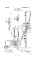
- Figure 1 is a plan view of the frogless switch constructed in accordance with this invention, the parts being arranged to provide continuous rails for the main line.
- Fig. 2 is a transverse sectional view taken substantially on the line 2 2 of Fig. 1.
- Fig. 3 is an enlarged detail perspective view of a portion of the switch, illustrating the construction of the laterally-movable substantially V-shaped rail and showing the same arranged to form a continuous rail for the siding.
- Fig. 4 is a horizontal sectional view of the same, the movable V-shaped rail be ing arranged as shown in Fig. 1 to form a continuous main-line rail.
- Fig. 5 is a detail transverse sectional view on the line 5 5 of Fig. 1.
- Fig. 6 is a detail transverse sectional view on the line 6 6 of Fig. 4.
- Fig. 7 is a similar view on the line 7 7 of Fig. 4.
- Fig. 8 is a detail perspective view of the slidable locking-wedge .which holds the V- shaped rail against lateral movement when the switch is set.
- Fig. 9 is a detail perspective view of the guide for the slidable wedge.
- Fig. 10 is a detail perspective view of the upper arm of the vertical rock-shaft of the switch-lockin mechanism.
- Fig. 11 is an enlarged detai sectional view on the line 11 11 of Fig. 1.
- Fig. 12 is a similar view on the line 12 12 of Fig. 1.
- 1 and 2 designate fixed sections of the inner main-line rail, which is located adjacent to the siding-rails 3 and 4 and which is cut at the crossover or point usually occupied by a frog to provide a space for a laterally-movable substantially V-shaped rail 5, which is adapted to form either a continuous main- I line rail or a continuous siding-rail at the crossover or point of intersection of the inner main-line rail and the inner siding-rail, thereby preventing the accidents which result from the use of a frog.
- the laterallymovable substantially V-shaped rail is provided with a short side or member 6, which is adapted to form a continuation of and complete the inner rail of the siding, as clearly illustrated in Fig.
- the said short side or member and the adjacent portion of the other side or memberof the V-shaped piece or rail is arranged upon ,a base or bed plate 7.
- the two sides or members of the V-shaped rail or piece are,bolted or otherwise secured to a tapered or wedgeshaped block 8, having a reduced rear por tion through which extends an upturned end 9 of a transverse rod 10.
- the upturned end which pierces the block 8 and which is threaded to receive a nut, operates in a transverse slot 7 a of the base or bed plate 7, the slot being provided to permit the necessary lateral movement of the V-shaped rail or piece.
- the sides or members are also connected by a transverse rod or bolt 11, on which is arranged a spacing-sleeve 12, which is interposed between the sides or members near the rear or outer end of the short side or member 6.
- the long side or member is connected with the adjacent portion or section 1 of the main-line rail by means of angle fishplates 13, which are reduced to form resilient extensions or tongues 14.
- the angle-body portions of the fish-plates 13 are bolted to the main-rail section 1, and the resilient tongues 14, which consist of extensions of the vertical flanges'of the angle-body portions of the fish-plates, are-secured to the long side of the V-shaped rail or piece, which is adapted to move laterally 0n the bed or base plate.
- the V-shaped rail or member is constructed of separate rails secured together, as shown, to enable it to be conveniently made in an ordinary shop; but itwill be readily apparent that this movable rail-carrying member may be constructed in any other desired manner and may be provided with rail elements of any preferred construction.
- the bed or base plate which is secured to.
- the adjacent cross-ties forms a firm and rigid support for .
- the V-shaped rail or piece and it is provided at opposite sides with fixed jaws or clamp members 15 and 16, having up- WfiIdlY-BXteIldiIlg, angularly-disposed portions adapted to conform to the configuration of the lower portions of the sides or members of the'V-shaped rail or piece.
- the bed or base/plate is also provided with fixed clamping-jaws 17, 18, and 19, located at opposite ends of the base-plate.
- the fixed clamping-jaws 17 engage the opposite sides of the inner siding-rail 3
- the clamping-j aw 18 engages the outer side of the main-rail section 2
- the jaw 19 engages the outer side of the section 20 of the inner siding-rail.
- the section 20 consists of a fixed rail and is located between the main rails, as clearly shown in Fig. 1 of the drawings.
- the fixed rails or rail-sections 2 and 20 are braced by a spacing-sleeve 21, interposed between them and disposed on a transverse rod or bolt 22.
- the movable switch-rails 23 and 24 are hinged, by means of fish-plates, to the adj acent ends of the main-rail section 2 and the inner siding-rail or section 20, and they are connected by a transverse bar 25.
- the switch-rail 24 is movable to and from the outer main rail 26, which is continuous, and the other switch rail 23 is movable to and from the main rail 27, which in practice mergesinto and forms a continuation of the outer siding-rail 28.
- the switch-rail 24 When the switch-rail 24 is moved away from the main rail 26, as shown in Fig. 1 of the drawings, the switch is setfor the main line and continuous main line rails are provided, and as there is no frog or break in the rails the accidents resulting from the use of frogs will be eliminated.
- the switch-rails When the switch-rails are moved to their other-position and the rail 24 is in contact with the main rail 26, the switch will be set for the siding and continuous rails will be provided.
- the transverse bar 25 is provided with upturned ends, which are bolted to the movable switch-rails at an intermediate point. The said bar 25 is connected by a transverse rod 29 with a switchoperating lever 30 of a switch-stand, which is provided with a box or casing 31.
- the lever which is arranged in an upright position, is fulcrumed between its ends within the box or casing 3 1 on a horizontal rod or bolt 32, the upper end of the lever being shaped into a handle and the lower end being pivoted to the outer end of the transverse rod 29.
- the lower end of the switchoperating lever is also connected by an outer transverse rod 33 with one arm of a bellcrank lever 34, which has its other arm connected by a longitudinal rod 35 with a bellcrank lever 36.
- the bell-crank lever 36 communicates motion from the rod 35 to the transverse rod 10, which is connected with the V-shaped rail or piece by means of the said block 8.
- the box or casing of the stand is provided in its top with a slot or opening 37, through which passes the upper arm of the switch-operating lever, and the latter,
- the bell-crank lever 34 is also connected by a rod or bar 38 with a switch-target 39.
- the tar get which may be of any desired construction, is of the rotary type and is provided with an arm 40, which is pivoted to the bar 38.
- the target is also provided with a suitable light 41 for indicating at night the position of the switch.
- the switch is provided with looking mechanism for simultaneously locking the V- shaped piece or rail and the switch-operating lever against movement to prevent the same from becoming accidentally dis laced after the switch has been set for eithert e main line or the siding.
- This locking mechanism comprises a slidable locking device consistin of a wedge or block 42, movable longitudina ly of the track and mounted between the mainrail section 2 and the inner siding-rail section and adapted tooverlap the fixed main-rail section 2 and the apex of the movable V- shaped rail or piece.
- the slidable wedge or block which is adapted to engage either side ofthe V-shaped rail or piece, as clearly illus-.,
- a horizontal web 43 extending along the median line of the wedge or block at one side thereof from the apex to within a short distance of the base or enlarged end 44, which forms a stop for limiting the forward movement of the slidable wedge or member 42.
- the web or flange 43 slides in a groove 45 of a guide-block 46, and the opposite side face 47 of the slidable wedge or block conforms to the configuration of the adjacent rail and extends beneath the head thereof, whereby it is guided in its movement and retained in position, as clearly illustrated in Fig. 7 of the drawings.
- the guide 46 is tapered or wedge-shaped and is provided at the enlarged end with an angular extension or angle-plate 48, which is bolted or otherwise secured to the adjacent rail 20.
- the guiding-face of the tapering or wedge-shaped guide 46 is set at an angle, and the side edge of the horizontal web or flange 43 is also set at an angle and slides on the said guidingface, as clearly illustrated in Fig. 4 of the drawings, whereby when the wedge is moved forward to its engaging position for locking the movable V-shaped rail or piece it will be firmly wedged in such engaging position and will retain the movable V-shaped rail or piece rigidly in engagement with one of the clamping-jaws 15 and 16 of the base or bed plate.
- the guide-block 46 which is fastened to the fixed rail 20, provides a lateral extension for partially closing the space between the rails 2 and 20, and the slidable wedge or block is interposed between the guide-block and the rail 2, the two blocks filling the space between the said rails 2 and 20.
- the guide-block and the slidable wedge or block fit in and fill the space between the heads and the bottom flanges of the said rails and have their upper faces flush.
- the block and the slidable locking device extend entirely across the space between the rails 2 and 20 and as they also fit in and fill the space between the heads and bottom flanges of the rails, there is no liability of the foot of the person being caught between the said rails 2 and 20 and a frog-guard for this purpose is unnecessary.
- the upper faces of the guide-block and the slidable block or wedge are located at the lower edges or faces of the heads of the rails, and sufficient space is thereby provided between them and the treads of the rails for the passage of the flanges of car-wheels.
- the slidable locking wedge or member 42 is connected with a threaded end 49 of a rod, and it has a threaded socket for the reception of the rod, as clearly illustrated in Fig. 4 of the drawings.
- the rod 50 which extends longitudinally of the main line, is connected at its other end with the inner arm of a transverse lever 51, fnlcrumed between its ends on a bolt 52 or other suitable fastening device and having its outer arm connected by a rod 53 with a lower arm 54 of a vertical rockshaft 55.
- the inner arm of the transverse lever is perforated to receive the adjacent end of the rod 50, which is bent upward to form a pivot and which is provided with upper and lower nuts for retaining it in the perforation of the inner arm of the lever 51.
- the pivot or bolt 52 depends from a bar 56, which spans the space between two cross-ties and which has its ends suitably secured to the latter.
- the vertical rock-shaft is journaled in upper and lower bearings of the box or casing of the switch-stand, the upper bearing being formed in the top of the box or switch-stand and the lower bearing being formed in a bracket 57.
- the bracket 57 is arranged within the box or casing of the switch-stand, and it extends horizontally from one of the walls thereof.
- the upper end of the rock shaft is provided with a squared portion 58, and it receives an upper arm 59, which is provided with a square opening 60 to fit the squared portion of the rock-shaft and which is secured to the same by a nut 61, arranged 011 a threaded portion of the upper end of the rock-shaft.
- the rock-shaft is adapted to be partially rotated, and motion is communicated from its lower arm to the transverse lever 51, which reciprocates the slidable wedge or member.
- the upper arm 59 of the rock-shaft extends in a direction transversely of the track and is arranged at one side of the switch-operating lever 30, and in order to lock the switch-operating lever against accidental movement the upper arm of the rock-shaft is provided with a laterally-projecting lug 61*, which is adapted to engage either the inner or outer edge of the lever 30.
- the lug 61 of the upper arm is adapted to engage the outer edge of the said lever, and when the said upper arm is at the limit of its outward movement the lug 61 will engage its inner edge.
- the outer end 62 of the upper arm of the vertical rock-shaft is bifurcated to re ceive one end of a foldable handle 63, which is pivoted in the bifurcation by a transverse pin 64 and which is adapted to be swung upward to a horizontal position for operating the rock-shaft and which is also adapted to be swung downward and folded against the exterior of the box or casing of the stand into engagement with a keeper 65.
- a keeper 65 When it is in engagement with the keeper 65, it forms a gravity-lock and is adapted to be used temporarily for holding the upper arm 59 in its engaging position.
- the keeper 65 consists of a plate or piece provided with outwardly-extending spaced lugs arranged to receive the handle of the lever between them.
- the inner pivoted end of the handle 63 is provided with an extension 66, adapted to limit the upward swing of the handle, and the outer end of the arm is pro vided at the inner end of the bifurcation with a recess for the reception of the extension 66, which is flush with the upper face of the arm 59 when the handle is in a horizontal position.
- the arm 59 is provided at its outer edge with a depending hasp member 67, having a slot for the reception of a staple 68 and adapted to be carried into and out of engagement with it by the oscillation of the arm 59.
- the arm 59 is in its engaging position, the staple extends through the slot or opening of the hasp member 67 and is adapted to receive the shackle of a padlock 69, as clearly illustrated in Fig. 1 of the drawings.
- the upper arm of the looking mechanism is positively locked in engagement with the operating-arm of the switch.
- the switch is simple and comparatively inexpensive in construction, that it is ada ted to be easily made at a shop, and that it 1s adapted to afford continuous rails from terminal to terminal of a railroad. Also it will be apparent that the switchop erating lever and the laterally-movable V- shaped rail or piece are simultaneously locked and positively held against movement by the locking member, and that the outward movement of the upper arm of the vertical rock-shaft simultaneouslyreleases the switchoperating lever and the V-shaped rail or piece.
- a railway-switch the combination with two spaced rails arranged at an angle, and a movable member, of a tapered guideblock secured to one of the rails and having an angularly-disposed guiding-face, and a wedge-shaped locking device fitted between the guide and the opposite rail'ior locking the movable member.
- I 10. In a railway-switch, the combination with two rails, and a movable member, of a grooved-guide arranged between the rails, and a wedge-shaped locking device provided with a web operating inthe groove of the guide and terminating short of the rear end of the wedge-shaped locking device, the latter being provided with a stop for limiting its movement.
- a movable member comprising two rails arranged at an angle and secured together, a tapered block interposed between the rails and secured to and connecting the same, and
- a movable V-shaped member composed of two rails secured together at the apex of the member, a tapered block interposed between and secured to and connecting the contiguous ends of the rails, means for connecting the rails in rear of the block, and means for operating the movable member.
- a bed-plate provided with a slot
- a movable member having angularly-disposed rails and provided with an interposed wedgeshaped block secured to and connecting the rails, and operating mechanism extending through the slot of the bed-plate and connected with the block.
- a movable member having angularly-disposed rails and provided with an interposed wedge-shaped block secured to the rails and having a reduced portion, and operating mechanism connected with the reduced por tion of the block.
- a railway-switch the combination with two rails, of a movable member provided with rail-sections arranged to form continuations of the said rails, and fishplates secured to one of the rails and provided with reduced resilient extensions connected to one of the rail-sections and forming a splice and hinging the movable member.
- arailway-switch The combination of arailway-switch, a switch-stand having a switch-operating lever, and locking mechanism for the switch having an oscillatory arm mounted on the switch-stand and provided with means for engaging the said lever, and a lock for securing the arm to the switch-stand.
Landscapes
- Engineering & Computer Science (AREA)
- Mechanical Engineering (AREA)
- Architecture (AREA)
- Civil Engineering (AREA)
- Structural Engineering (AREA)
- Train Traffic Observation, Control, And Security (AREA)
Description
PATENTED SEPT. 25, 1906.
G. M. AYLES.
PROGLESS SWITCH.
APPLICATION FILED MAY19,1906.'
8 SHEETS-SHEET 1.
PATENTED SEPT. 25, 1906.
G. M. AYLES.
PROGLESS SWITGH.
APPLICATION 1 1L 21) MAY 19,1905.
SHEETS-SHEET 2.
m: Noam: Psrsn'; 20., wasinr cmn, L\ c PATENTED SEPT. 25, 1906.
G. M. AYLES. FROGLESS SWITCH.
APPLICATION FILED MAY19.1B05.
SHEBT 3.
3 SHEETS GEORGE M. AYLES, OF NEW ALBANY, INDIANA.
FROGLESS SWITCH.
Specification of Letters Patent.
Patented Sept. 25, 1906.
Applicationfiled May 19,1905. Serial No. 261,188.
To all whom it may concern/.-
Be it'known that I, GEORGE M. AYLEs, a citizen of the United States, residing at New Albany, in the county of Floyd and State of Indiana, have invented a new and useful Frogless Switch, of which the following is a specification.
The invention relates to improvements in frogless switches.
The object of the present invention is to improve the construction of railway-switches and to increase the strength, durability, and efficiency of the same and to provide a simple and comparatively inexpensive frogless switch adapted to provide a continuous rail from terminal to terminal of a railway, and thereby prevent the accidents resulting from the use of frogs.
A further object of the invention is to provide a switch of this character having means for simultaneously locking the switch-operating lever and the movable rail, which takes the place of a frog, whereby the switch after being once set either for the main line or the siding will be effectually prevented from becoming accidentally displaced.
With these and other objects in view the invention consists in the construction and novel combination and arrangement of parts hereinafter fully described, illustrated in the accompanying drawings, and pointed out in the claims hereto appended, it being understood that various changes in the form, proportion, size, and minor details of construction within the scope of the claims may be resorted to without departing from the spirit or sacrificing any of the advantages of the invention.
In the drawings, Figure 1 is a plan view of the frogless switch constructed in accordance with this invention, the parts being arranged to provide continuous rails for the main line. Fig. 2 is a transverse sectional view taken substantially on the line 2 2 of Fig. 1. Fig. 3 is an enlarged detail perspective view of a portion of the switch, illustrating the construction of the laterally-movable substantially V-shaped rail and showing the same arranged to form a continuous rail for the siding. Fig. 4 is a horizontal sectional view of the same, the movable V-shaped rail be ing arranged as shown in Fig. 1 to form a continuous main-line rail. Fig. 5 is a detail transverse sectional view on the line 5 5 of Fig. 1. Fig. 6 is a detail transverse sectional view on the line 6 6 of Fig. 4. Fig. 7 is a similar view on the line 7 7 of Fig. 4. Fig. 8 is a detail perspective view of the slidable locking-wedge .which holds the V- shaped rail against lateral movement when the switch is set. Fig. 9 is a detail perspective view of the guide for the slidable wedge. Fig. 10 is a detail perspective view of the upper arm of the vertical rock-shaft of the switch-lockin mechanism. Fig. 11 is an enlarged detai sectional view on the line 11 11 of Fig. 1. Fig. 12 is a similar view on the line 12 12 of Fig. 1.
Like numerals of reference designate corresponding parts in all the figures of the draw mgs.
1 and 2 designate fixed sections of the inner main-line rail, which is located adjacent to the siding-rails 3 and 4 and which is cut at the crossover or point usually occupied by a frog to provide a space for a laterally-movable substantially V-shaped rail 5, which is adapted to form either a continuous main- I line rail or a continuous siding-rail at the crossover or point of intersection of the inner main-line rail and the inner siding-rail, thereby preventing the accidents which result from the use of a frog. The laterallymovable substantially V-shaped railis provided with a short side or member 6, which is adapted to form a continuation of and complete the inner rail of the siding, as clearly illustrated in Fig. 3 of the drawings, and the said short side or member and the adjacent portion of the other side or memberof the V-shaped piece or rail is arranged upon ,a base or bed plate 7. The two sides or members of the V-shaped rail or piece are,bolted or otherwise secured to a tapered or wedgeshaped block 8, having a reduced rear por tion through which extends an upturned end 9 of a transverse rod 10. The upturned end, which pierces the block 8 and which is threaded to receive a nut, operates in a transverse slot 7 a of the base or bed plate 7, the slot being provided to permit the necessary lateral movement of the V-shaped rail or piece. The sides or members are also connected by a transverse rod or bolt 11, on which is arranged a spacing-sleeve 12, which is interposed between the sides or members near the rear or outer end of the short side or member 6. The long side or member is connected with the adjacent portion or section 1 of the main-line rail by means of angle fishplates 13, which are reduced to form resilient extensions or tongues 14. The angle-body portions of the fish-plates 13 are bolted to the main-rail section 1, and the resilient tongues 14, which consist of extensions of the vertical flanges'of the angle-body portions of the fish-plates, are-secured to the long side of the V-shaped rail or piece, which is adapted to move laterally 0n the bed or base plate. The V-shaped rail or member is constructed of separate rails secured together, as shown, to enable it to be conveniently made in an ordinary shop; but itwill be readily apparent that this movable rail-carrying member may be constructed in any other desired manner and may be provided with rail elements of any preferred construction.
The bed or base plate, which is secured to.
the adjacent cross-ties, forms a firm and rigid support for .the V-shaped rail or piece, and it is provided at opposite sides with fixed jaws or clamp members 15 and 16, having up- WfiIdlY-BXteIldiIlg, angularly-disposed portions adapted to conform to the configuration of the lower portions of the sides or members of the'V-shaped rail or piece. The bed or base/plate is also provided with fixed clamping- jaws 17, 18, and 19, located at opposite ends of the base-plate. The fixed clamping-jaws 17 engage the opposite sides of the inner siding-rail 3, the clamping-j aw 18 engages the outer side of the main-rail section 2, and the jaw 19 engages the outer side of the section 20 of the inner siding-rail. The section 20 consists of a fixed rail and is located between the main rails, as clearly shown in Fig. 1 of the drawings. The fixed rails or rail- sections 2 and 20 are braced by a spacing-sleeve 21, interposed between them and disposed on a transverse rod or bolt 22. The movable switch-rails 23 and 24 are hinged, by means of fish-plates, to the adj acent ends of the main-rail section 2 and the inner siding-rail or section 20, and they are connected by a transverse bar 25. The switch-rail 24 is movable to and from the outer main rail 26, which is continuous, and the other switch rail 23 is movable to and from the main rail 27, which in practice mergesinto and forms a continuation of the outer siding-rail 28. When the switch-rail 24 is moved away from the main rail 26, as shown in Fig. 1 of the drawings, the switch is setfor the main line and continuous main line rails are provided, and as there is no frog or break in the rails the accidents resulting from the use of frogs will be eliminated. When the switch-rails are moved to their other-position and the rail 24 is in contact with the main rail 26, the switch will be set for the siding and continuous rails will be provided. The transverse bar 25 is provided with upturned ends, which are bolted to the movable switch-rails at an intermediate point. The said bar 25 is connected by a transverse rod 29 with a switchoperating lever 30 of a switch-stand, which is provided with a box or casing 31. The lever, which is arranged in an upright position, is fulcrumed between its ends within the box or casing 3 1 on a horizontal rod or bolt 32, the upper end of the lever being shaped into a handle and the lower end being pivoted to the outer end of the transverse rod 29. The lower end of the switchoperating lever is also connected by an outer transverse rod 33 with one arm of a bellcrank lever 34, which has its other arm connected by a longitudinal rod 35 with a bellcrank lever 36. The bell-crank lever 36 communicates motion from the rod 35 to the transverse rod 10, which is connected with the V-shaped rail or piece by means of the said block 8. The box or casing of the stand is provided in its top with a slot or opening 37, through which passes the upper arm of the switch-operating lever, and the latter,
which is provided at its upper arm with a suitable grip or handle, is adapted to be oscillated to move the switch-rails and the V- shaped rail or piece simultaneously. The bell-crank lever 34 is also connected by a rod or bar 38 with a switch-target 39. The tar get, which may be of any desired construction, is of the rotary type and is provided with an arm 40, which is pivoted to the bar 38. The target is also provided with a suitable light 41 for indicating at night the position of the switch.
The switch is provided with looking mechanism for simultaneously locking the V- shaped piece or rail and the switch-operating lever against movement to prevent the same from becoming accidentally dis laced after the switch has been set for eithert e main line or the siding. This locking mechanism comprises a slidable locking device consistin of a wedge or block 42, movable longitudina ly of the track and mounted between the mainrail section 2 and the inner siding-rail section and adapted tooverlap the fixed main-rail section 2 and the apex of the movable V- shaped rail or piece. The slidable wedge or block, which is adapted to engage either side ofthe V-shaped rail or piece, as clearly illus-.,
trated in Figs. 1, 3, and 4 of the drawings, fits against the inner face of the main-rail section 2 and is provided with a horizontal web 43, extending along the median line of the wedge or block at one side thereof from the apex to within a short distance of the base or enlarged end 44, which forms a stop for limiting the forward movement of the slidable wedge or member 42. The web or flange 43 slides in a groove 45 of a guide-block 46, and the opposite side face 47 of the slidable wedge or block conforms to the configuration of the adjacent rail and extends beneath the head thereof, whereby it is guided in its movement and retained in position, as clearly illustrated in Fig. 7 of the drawings. The guide 46 is tapered or wedge-shaped and is provided at the enlarged end with an angular extension or angle-plate 48, which is bolted or otherwise secured to the adjacent rail 20. The guiding-face of the tapering or wedge-shaped guide 46 is set at an angle, and the side edge of the horizontal web or flange 43 is also set at an angle and slides on the said guidingface, as clearly illustrated in Fig. 4 of the drawings, whereby when the wedge is moved forward to its engaging position for locking the movable V-shaped rail or piece it will be firmly wedged in such engaging position and will retain the movable V-shaped rail or piece rigidly in engagement with one of the clamping- jaws 15 and 16 of the base or bed plate. The guide-block 46, which is fastened to the fixed rail 20, provides a lateral extension for partially closing the space between the rails 2 and 20, and the slidable wedge or block is interposed between the guide-block and the rail 2, the two blocks filling the space between the said rails 2 and 20. As clearly shown in Fig. 7, the guide-block and the slidable wedge or block fit in and fill the space between the heads and the bottom flanges of the said rails and have their upper faces flush. As the block and the slidable locking device extend entirely across the space between the rails 2 and 20 and as they also fit in and fill the space between the heads and bottom flanges of the rails, there is no liability of the foot of the person being caught between the said rails 2 and 20 and a frog-guard for this purpose is unnecessary. The upper faces of the guide-block and the slidable block or wedge are located at the lower edges or faces of the heads of the rails, and sufficient space is thereby provided between them and the treads of the rails for the passage of the flanges of car-wheels.
The slidable locking wedge or member 42 is connected with a threaded end 49 of a rod, and it has a threaded socket for the reception of the rod, as clearly illustrated in Fig. 4 of the drawings. The rod 50, which extends longitudinally of the main line, is connected at its other end with the inner arm of a transverse lever 51, fnlcrumed between its ends on a bolt 52 or other suitable fastening device and having its outer arm connected by a rod 53 with a lower arm 54 of a vertical rockshaft 55. The inner arm of the transverse lever is perforated to receive the adjacent end of the rod 50, which is bent upward to form a pivot and which is provided with upper and lower nuts for retaining it in the perforation of the inner arm of the lever 51. The pivot or bolt 52 depends from a bar 56, which spans the space between two cross-ties and which has its ends suitably secured to the latter.
The vertical rock-shaft is journaled in upper and lower bearings of the box or casing of the switch-stand, the upper bearing being formed in the top of the box or switch-stand and the lower bearing being formed in a bracket 57. The bracket 57 is arranged within the box or casing of the switch-stand, and it extends horizontally from one of the walls thereof. The upper end of the rock shaft is provided with a squared portion 58, and it receives an upper arm 59, which is provided with a square opening 60 to fit the squared portion of the rock-shaft and which is secured to the same by a nut 61, arranged 011 a threaded portion of the upper end of the rock-shaft. The rock-shaft is adapted to be partially rotated, and motion is communicated from its lower arm to the transverse lever 51, which reciprocates the slidable wedge or member.
- When the slidable wedge or member is in engagement with the movable V-shaped rail or piece, the upper arm 59 of the rock-shaft extends in a direction transversely of the track and is arranged at one side of the switch-operating lever 30, and in order to lock the switch-operating lever against accidental movement the upper arm of the rock-shaft is provided with a laterally-projecting lug 61*, which is adapted to engage either the inner or outer edge of the lever 30. When the upper arm of the switch-operating lever is at the limit of its inward movement, the lug 61 of the upper arm is adapted to engage the outer edge of the said lever, and when the said upper arm is at the limit of its outward movement the lug 61 will engage its inner edge. The outer end 62 of the upper arm of the vertical rock-shaft is bifurcated to re ceive one end of a foldable handle 63, which is pivoted in the bifurcation by a transverse pin 64 and which is adapted to be swung upward to a horizontal position for operating the rock-shaft and which is also adapted to be swung downward and folded against the exterior of the box or casing of the stand into engagement with a keeper 65. When it is in engagement with the keeper 65, it forms a gravity-lock and is adapted to be used temporarily for holding the upper arm 59 in its engaging position. This may be advantageously employed while shifting cars or when running a train upon a siding or the like, and the weight of the pivoted arm will retain it positively in engagement with the keeper. The keeper 65 consists of a plate or piece provided with outwardly-extending spaced lugs arranged to receive the handle of the lever between them. The inner pivoted end of the handle 63 is provided with an extension 66, adapted to limit the upward swing of the handle, and the outer end of the arm is pro vided at the inner end of the bifurcation with a recess for the reception of the extension 66, which is flush with the upper face of the arm 59 when the handle is in a horizontal position. The arm 59 is provided at its outer edge with a depending hasp member 67, having a slot for the reception of a staple 68 and adapted to be carried into and out of engagement with it by the oscillation of the arm 59. the arm 59 is in its engaging position, the staple extends through the slot or opening of the hasp member 67 and is adapted to receive the shackle of a padlock 69, as clearly illustrated in Fig. 1 of the drawings. By this construction the upper arm of the looking mechanism is positively locked in engagement with the operating-arm of the switch.
It will be seen that the switch is simple and comparatively inexpensive in construction, that it is ada ted to be easily made at a shop, and that it 1s adapted to afford continuous rails from terminal to terminal of a railroad. Also it will be apparent that the switchop erating lever and the laterally-movable V- shaped rail or piece are simultaneously locked and positively held against movement by the locking member, and that the outward movement of the upper arm of the vertical rock-shaft simultaneouslyreleases the switchoperating lever and the V-shaped rail or piece.
Having thus fully described my invention, what I claim as new, and desire to secure by Letters Patent, is-
1. In a railwayswitch, the combination with two spaced rails, and a movable member, ofa block partially closing the space between the rails, and a locking device movable on the block for locking the said movable member.
2. In a railway-switch, the combination with two rails, and a movable member, of a block located between the rails, and locking mechanism for the movable member, said locking mechanism having a slidable element guided by the block.
3. In a railway-switch, the combination with two rails, and a movable member, of a block mounted between the rails, and a slidable locking device for the movable member interposed between the block and one of the rails and guided by one of the said parts.
4. In a railway-switch, the combination with two spaced rails, and a movable member, of a block secured to one of the rails and partially closing the space between the same, and a slidable locking device filling the space between the block and the opposite rail and arranged to engage the said member.
5. In a railway-switch, the combination with two spaced rails, and a movable member, of a block secured to one of the rails, and a slidable locking device interposed between the other rail and the block, said locking device and block filling the space between the head and bottom flange of each rail and arranged flush with each other.
6. In a railway-switch, the combination with two rails arranged at an angle, and a When 'movable member, of a tapered block secured to one of the rails, and a wedge-shaped locking device operating between the block and the opposite rail for locking the movable member.
7. In a railway-switch, the combination with two rails, and a movable member, of a guide-block secured to one of the rails and provided with a groove, and a slidable looking device fitting in the groove of the guideblock and operating between the latter and the opposite rail for locking the said member.
8. In a railway-switch, the combination with two rails, and a movable member, of a guide-block secured to one of the rails and having an angularly-disposed guiding-face, and a wedge-shaped locking device fitted between the said guide-block and the opposite rail for locking the movable member.
9. In. a railway-switch, the combination with two spaced rails arranged at an angle, and a movable member, of a tapered guideblock secured to one of the rails and having an angularly-disposed guiding-face, and a wedge-shaped locking device fitted between the guide and the opposite rail'ior locking the movable member. I 10. In a railway-switch, the combination with two rails, and a movable member, of a grooved-guide arranged between the rails, and a wedge-shaped locking device provided with a web operating inthe groove of the guide and terminating short of the rear end of the wedge-shaped locking device, the latter being provided with a stop for limiting its movement.
11. In a railway-switch, the combination of a movable member comprising two rails arranged at an angle and secured together, a tapered block interposed between the rails and secured to and connecting the same, and
means for operating the movable member.
12. In a railway-switch, the combination of a movable V-shaped member composed of two rails secured together at the apex of the member, a tapered block interposed between and secured to and connecting the contiguous ends of the rails, means for connecting the rails in rear of the block, and means for operating the movable member.
13. In a railway-switch, the combination of a bed-plate provided with a slot, a movable member having angularly-disposed rails and provided with an interposed wedgeshaped block secured to and connecting the rails, and operating mechanism extending through the slot of the bed-plate and connected with the block.
14. In a railway-switch, the combination of a movable member having angularly-disposed rails and provided with an interposed wedge-shaped block secured to the rails and having a reduced portion, and operating mechanism connected with the reduced por tion of the block.
15. In a railway-switch, the combination with two rails, of a movable member provided with rail-sections arranged to form continuations of the said rails, and fishplates secured to one of the rails and provided with reduced resilient extensions connected to one of the rail-sections and forming a splice and hinging the movable member.
16. The combination of a railway-switch, locking mechanism for the switch, means for manually operating the switch, and separate manuallyoperated means for operating the locking mechanism, the said manually-operated means also serving to lock the switchoperating mechanism.
17. The combination of a railway-switch, manually-operated means for operating the same, and manuallyoperated means for locking the switch and for also locking the switchoperating means, each of the said means being operable independently of the other.
18. The combination of a railway-switch embodying movable switch-rails, and a movable member carrying rail elements, operating mechanism for the switch, and locking mechanism provided with means for simultaneously engaging the switch operating mechanism and the said movable member.
19. The combination of a railway-switch having a movable member, operating mechanism for the switch, and locking mechanism comprising a movable locking device for engaging the said member, and means for simultaneously engaging the switch-operating mechanism.
20. The combination of a railway-switch having a movable member, switch-operating mechanism, and locking mechanism comprising a locking device for engaging the movable member, and an oscillatory operating-arm having means for engaging the switch-operating mechanism.
21. The combination of a railway-switch having a movable member, an operating-lever for the switch, and locking mechanism comprising a movable locking device for en gaging the said member, and an oscillatory operating-arm having means for engaging the said lever.
22. The combination of a railway-switch, an operating lever therefor, and locking mechanism comprising a locking device for engaging the switch, and an oscillatory arm for engaging the lever.
23. The combination of a railway-switch, an operating lever therefor, and locking mechanism for the switch, said locking mechanism having an oscillatory arm provided with a projecting portion arranged to lock the operating-lever in its adjustment.
24:. The combination of arailway-switch, a switch-stand having a switch-operating lever, and locking mechanism for the switch having an oscillatory arm mounted on the switch-stand and provided with means for engaging the said lever, and a lock for securing the arm to the switch-stand.
25. The combination of a railway-switch, a switch-stand having a switch-operating lever, and locking mechanism for the switch comprising an oscillatory arm mounted on the switch-stand and provided with means for engaging the said lever, a hasp carried by the arm, and astaple arranged to engage the hasp and adapted to receive a lock.
26. The combination of a railway-switch, a switch-stand having an operating-lever, an oscillatory arm mounted on the switch-stand and provided with means for engaging the lever, and a handle pivoted to the arm and arranged to fold against the switch-stand, said switch-stand being provided with means for engaging the handle.
27. The combination of a railway-switch, a switch-stand having an operatinglever, an oscillatory arm mounted on the switch-stand and provided with means for engaging the lever, a handle pivoted to the arm, and a keeper mounted on the switch-stand and arranged to receive and engage the pivoted handle.
28. The combination of a railwayswitch, a switch-stand having an operating-lever, and locking mechanism comprising a movable locking device, a rock-shaft mounted in the switch-stand and provided with an arm arranged to engage the operating-lever, and means for connecting the rock-shaft with the locking device.
29. The combination of a railway-switch, a switch-stand having an operating-lever, and locking mechanism embodying a movable locking device, a rock-shaft mounted in the switch-stand and provided with upper and lower arms, the upper arm having means for engaging the operating-lever, a transverse lever, and means for connecting the transverse lever with the movable locking device and with the lower arm of the rockshaft.
30. In a railway-switch, the combination with a movable member, of two spaced rails, one of the rails being provided with a lateral extension partially filling the space between the rails, and a slidable locking device interposed between the extension and the opposite rail and guided by one of the said parts for locking the movable member.
31. In a railway-switch, the combination with two spaced rails, and a movable member, of a block secured to one of the rails and partially closing the space between the same, and a slidable locking device interposed between the block and the other rail for locking the movable member, said block and locking device fitting in and filling the space between the heads and bottom flanges of the rails.
32. The combination with a fixed rail, and a movable rail, of connecting means for the said rails, said connecting means embodying a fish-plate consisting of an angle body por- 2 my own I have hereto affixed my signature Eon havi'gg a Veritical flangfe and a1 bottgm in the presence of two Witnesses.
ange an secure to one 0 the rai s, an a flat resilient tongue forming a continuation GEORGE AYLES' 5 of the vertical flange of the angle body por- Witnesses:
tion, and secured to the other rail. EVAN B. STATSENBURG,
In testimony that I claim the foregoing as J NO. H. WEATHERS.
Priority Applications (1)
| Application Number | Priority Date | Filing Date | Title |
|---|---|---|---|
| US26118305A US831762A (en) | 1905-05-19 | 1905-05-19 | Frogless switch. |
Applications Claiming Priority (1)
| Application Number | Priority Date | Filing Date | Title |
|---|---|---|---|
| US26118305A US831762A (en) | 1905-05-19 | 1905-05-19 | Frogless switch. |
Publications (1)
| Publication Number | Publication Date |
|---|---|
| US831762A true US831762A (en) | 1906-09-25 |
Family
ID=2900237
Family Applications (1)
| Application Number | Title | Priority Date | Filing Date |
|---|---|---|---|
| US26118305A Expired - Lifetime US831762A (en) | 1905-05-19 | 1905-05-19 | Frogless switch. |
Country Status (1)
| Country | Link |
|---|---|
| US (1) | US831762A (en) |
-
1905
- 1905-05-19 US US26118305A patent/US831762A/en not_active Expired - Lifetime
Similar Documents
| Publication | Publication Date | Title |
|---|---|---|
| US831762A (en) | Frogless switch. | |
| US144224A (en) | Improvement in railway-switches | |
| US745199A (en) | Railroad switch and track construction. | |
| US569653A (en) | Railroad-switch | |
| US245389A (en) | myers | |
| US618055A (en) | Railroad-switch | |
| US1150630A (en) | Reversible cross-tie for switches. | |
| US324773A (en) | Samuel ii | |
| US563027A (en) | Spring-rail frog | |
| US596859A (en) | downa | |
| US785559A (en) | Railroad-frog. | |
| US319675A (en) | Railroad-switch | |
| US747202A (en) | Railway-switch. | |
| US230095A (en) | Maeshall wood | |
| US285190A (en) | Kail way switch | |
| US253792A (en) | Railroad-switch | |
| US357189A (en) | Railroad-switch | |
| US256798A (en) | Oes to themselves | |
| US615101A (en) | Railway-switch | |
| US74951A (en) | Improved eailway-switoh | |
| US965685A (en) | Switch. | |
| US427166A (en) | Railway-switch | |
| US232171A (en) | Railway-switch | |
| US394681A (en) | Peter de long | |
| US206220A (en) | Improvement in railroad-switches |