US831749A - Last-turning machine. - Google Patents
Last-turning machine. Download PDFInfo
- Publication number
- US831749A US831749A US29407206A US1906294072A US831749A US 831749 A US831749 A US 831749A US 29407206 A US29407206 A US 29407206A US 1906294072 A US1906294072 A US 1906294072A US 831749 A US831749 A US 831749A
- Authority
- US
- United States
- Prior art keywords
- cutter
- last
- head
- shaft
- guide
- Prior art date
- Legal status (The legal status is an assumption and is not a legal conclusion. Google has not performed a legal analysis and makes no representation as to the accuracy of the status listed.)
- Expired - Lifetime
Links
- 238000010276 construction Methods 0.000 description 3
- 230000033001 locomotion Effects 0.000 description 3
- 239000000463 material Substances 0.000 description 2
- 239000002994 raw material Substances 0.000 description 2
- 230000003190 augmentative effect Effects 0.000 description 1
- 230000005540 biological transmission Effects 0.000 description 1
- 238000000034 method Methods 0.000 description 1
Images

Classifications
-
- B—PERFORMING OPERATIONS; TRANSPORTING
- B23—MACHINE TOOLS; METAL-WORKING NOT OTHERWISE PROVIDED FOR
- B23Q—DETAILS, COMPONENTS, OR ACCESSORIES FOR MACHINE TOOLS, e.g. ARRANGEMENTS FOR COPYING OR CONTROLLING; MACHINE TOOLS IN GENERAL CHARACTERISED BY THE CONSTRUCTION OF PARTICULAR DETAILS OR COMPONENTS; COMBINATIONS OR ASSOCIATIONS OF METAL-WORKING MACHINES, NOT DIRECTED TO A PARTICULAR RESULT
- B23Q11/00—Accessories fitted to machine tools for keeping tools or parts of the machine in good working condition or for cooling work; Safety devices specially combined with or arranged in, or specially adapted for use in connection with, machine tools
Definitions
- the invention resides in the shape and construction of the cutterhead and guide-wheel and in the positions of centers of the cutter-head and guide-wheel.
- the positions of the shafts of the cutter-head and guide-wheel are essentially on an an le with respect to the frame in order that t e model may bepermitted to turn free from ob-- structions during the process of turning.
- an auxiliary powertransmitting shaft is arranged behind the cutter-head shaft on the same angle as the latter in order that the power may be probably transmitted to the cutter-head shaft.
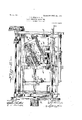
- Fi ure 1 is a perspective view of an old and wellnown form of last-turning machine .to which my lmprovements are applied.
- Fig. 2 1s a top plan view, various old and wellknown portions of the machine being omitted Specification of Letters Patent.-
- F g. 3 showsdetached detail views of the cutterhead.
- my invention consists in the construction of the cutter-head and the guide-wheel and in the positions in which they are mounted.
- the various portions of the framework and the driving spindles and wheels are old and well-known features of last-turning machines. Therefore it will scarcely be necessary to make more than a passing reference to these old and wellknown mechanical features.
- the lower framework 1, the bed 2, and the various superstructures 3 ,with primary and intermediate drive pulleys 4 and 5, are supplemented with various other old details, which need not here be referred to.
- the cutter-head shaft 6 is driven from the shaft 7 ,through belt 9, at a maximum rate of speed, the driving power being augmented by the addition of a flywheel 10 on the cutter-head shaft 6.
- the cutter-head 11 is securely fixed to the shaft 6 and consists of two uniformly outwardly and inwardly curved blades 12, the opposite edges of which operate upon the material as the cutter-head is rotated at a high'rate of speed.
- the power is'transmitted to the auxiliary shaft 7, which, as before stated, is belted to the cutter-head shaft 6 from pulley 4, through belt 45 said belt being passed around guide-pulleys 4 and twistedbetween said guide-pulleys 4 and the belt pulley 7 of the cutter-head shaft 6.
- guide-wheel is of a diameter that essen .tially corresponds with the diameter between the blades of the cutterhead 11, and the pe-' riphery of said guide-wheel is curved or rounded to agree with the rounded form of said cutter-blades.
- 1, l5 designates a model-last held in proximity to the cutter-wheels 13 and comprising a pattern-last for the cutter-head, the latter operating upon raw material in the form of a block reduced to'the proper size before being placed in position to be operated upon by the cutterhead.
- the pattern or model last 15 is held between centers 16 and 17 andis revolved at a suitable speed by means of gears 18 and 19, the former gear being on a shaft 20, upon which there is also a belt-pulley 21, which receives power from a belt-pulley 22 on the main power-shaft 23 at the bottom of the machine.
- the rotation thus imparted to the pattern or model last 15 is slow compared to the rotation of the cutter-head.
- the raw material to be operated upon by the cutter-head is held between revolving centers 24 and 25, which receive motion corresponding to the speed of rotation of the centers 16 and 17, owing to the gear 19' ofwthe revolving center 24 being of the same diameter as the gear 19 of revolving center 16.
- the gear 19 is driven from a gear 26 on shaft and is of equal diameter with gear 18 on said shaft.
- the guide-wheel 13 makes constant contact with the model-last 15 as the latter is moved longitudinally in contact with said guide-wheel.
- This movement is .the same as the movement given the raw maconsisting of two curved blades united at one end by an integral hub and spaced apart at the other end, a shaft upon which said cutterhead is mounted, said shaft being disposed at an angle to the plane of the material upon which the cutter-head operates, an auxiliary driving-shaft for said cutter-head shaft disposed upon an angle coinciding with the angle of the cutter-head shaft, and a guidew heel having a diameter coinciding, with the diameter of the cutter-head, the periphery of said guide-wheel also coinciding in curvature with the curvature of the cutting-blades of the cutter-head,substantially as specified.
Landscapes
- Engineering & Computer Science (AREA)
- Mechanical Engineering (AREA)
- Treatment Of Fiber Materials (AREA)
Description
No. 831,749. PATENTED SEPT. 25, 1906.
F. J. SHANISEY,B. LAST TURNING MACHINE.
APPLICATION FILED JAN. 2. 1906.
2 SHEETS-SHEET 1.
2 SHEETS-SHEET 2.
m y NNWWHHHHHHHW L N c I r PATENTED SEPT. 25, 1906.
F. J. SHANISEY, SR. LAST TURNING MACHINE.
APPLICATION FILED JAN.Z. 1906.
IHHHIII I HIHHIH Hm rm rfrnn srarns PATENT orrron.
. FREDERICK J. SHANISEY, SR., OF DAYTON, OHIO, AD'SIGNOR TO THE ORAWFORD-MGGREGOR & OANBY COMPANY, OF DAYTON, OHIO.
LAST-TURNING MACHINE.
companying drawings, and to the figures of referencemarked thereon, which form a part of this specification This invention relates to improvements in last-turning machines.
The construction of lasts to meet the requirements of the present time is such as to require a two-inch curvature on the sideof the last between the ball and the heel. With machines as now constructed it is impossible to turn such last, and the work is required to be done by hand. In constructing the last by hand it is impossible to obtain a perfect uniformity of curvature.
It is therefore the object of the present invention to provide a machine by which such curvature may be turned entirely from the cutter-head with great accuracy, thereby dispensing With the tedious and inaccurate handwork entirely.
Specifically speaking, the invention resides in the shape and construction of the cutterhead and guide-wheel and in the positions of centers of the cutter-head and guide-wheel.
The positions of the shafts of the cutter-head and guide-wheel are essentially on an an le with respect to the frame in order that t e model may bepermitted to turn free from ob-- structions during the process of turning.
in order to accomplish the purposes and ob ects of such machine, an auxiliary powertransmitting shaft is arranged behind the cutter-head shaft on the same angle as the latter in order that the power may be probably transmitted to the cutter-head shaft.
Preceding a detail description of my invention reference is made to the accompanying.
drawings, of which Fi ure 1 is a perspective view of an old and wellnown form of last-turning machine .to which my lmprovements are applied. Fig. 2 1s a top plan view, various old and wellknown portions of the machine being omitted Specification of Letters Patent.-
Application filed Januafy 2,1906. Serial No. 294,072.
thereby.
Patented Sept. 25, 1906.
in order to obtain a more perfect view of the mechanism comprised in the invention. F g. 3 showsdetached detail views of the cutterhead.
In a detail description of my invention similar reference characters indicate corresponding parts.
As hereinbefore stated, my invention consists in the construction of the cutter-head and the guide-wheel and in the positions in which they are mounted. The various portions of the framework and the driving spindles and wheels are old and well-known features of last-turning machines. Therefore it will scarcely be necessary to make more than a passing reference to these old and wellknown mechanical features. The lower framework 1, the bed 2, and the various superstructures 3 ,with primary and intermediate drive pulleys 4 and 5, are supplemented with various other old details, which need not here be referred to. Above the bed is mounted the cutter-head shaft 6 and auxiliary drivingshaft '7 in suitable bearings 8, said bearings being supported on the proper angles to imp art to said shafts the positions which are requisite for turning the desired curvature in the last, as shown in Fig. 2. The cutter-head shaft 6 is driven from the shaft 7 ,through belt 9, at a maximum rate of speed, the driving power being augmented by the addition of a flywheel 10 on the cutter-head shaft 6. The cutter-head 11 is securely fixed to the shaft 6 and consists of two uniformly outwardly and inwardly curved blades 12, the opposite edges of which operate upon the material as the cutter-head is rotated at a high'rate of speed. The power is'transmitted to the auxiliary shaft 7, which, as before stated, is belted to the cutter-head shaft 6 from pulley 4, through belt 45 said belt being passed around guide-pulleys 4 and twistedbetween said guide-pulleys 4 and the belt pulley 7 of the cutter-head shaft 6.
mitted to the cutter-head shaft through the necessary gearing, and thus the belt-and-pulley transmission devices are substituted 13 designates a guide-wheel mounted in an arm 14, which is rigidly secured to the frame.
It will of course be understood that the power may be trans- This, guide-wheel is of a diameter that essen .tially corresponds with the diameter between the blades of the cutterhead 11, and the pe-' riphery of said guide-wheel is curved or rounded to agree with the rounded form of said cutter-blades.
In 1, l5 designates a model-last held in proximity to the cutter-wheels 13 and comprising a pattern-last for the cutter-head, the latter operating upon raw material in the form of a block reduced to'the proper size before being placed in position to be operated upon by the cutterhead. The pattern or model last 15 is held between centers 16 and 17 andis revolved at a suitable speed by means of gears 18 and 19, the former gear being on a shaft 20, upon which there is also a belt-pulley 21, which receives power from a belt-pulley 22 on the main power-shaft 23 at the bottom of the machine. The rotation thus imparted to the pattern or model last 15 is slow compared to the rotation of the cutter-head. The raw material to be operated upon by the cutter-head is held between revolving centers 24 and 25, which receive motion corresponding to the speed of rotation of the centers 16 and 17, owing to the gear 19' ofwthe revolving center 24 being of the same diameter as the gear 19 of revolving center 16. The gear 19 is driven from a gear 26 on shaft and is of equal diameter with gear 18 on said shaft. The guide-wheel 13 makes constant contact with the model-last 15 as the latter is moved longitudinally in contact with said guide-wheel. This movement is .the same as the movement given the raw maconsisting of two curved blades united at one end by an integral hub and spaced apart at the other end, a shaft upon which said cutterhead is mounted, said shaft being disposed at an angle to the plane of the material upon which the cutter-head operates, an auxiliary driving-shaft for said cutter-head shaft disposed upon an angle coinciding with the angle of the cutter-head shaft, and a guidew heel having a diameter coinciding, with the diameter of the cutter-head, the periphery of said guide-wheel also coinciding in curvature with the curvature of the cutting-blades of the cutter-head,substantially as specified.
In testimony whereof I'aflix my signature in presence of two witnesses.
FREDERICK J. SHANISEY, SR.
Witnesses:
C. B. KYSER, Gus. L. BARRETT.
Priority Applications (1)
| Application Number | Priority Date | Filing Date | Title |
|---|---|---|---|
| US29407206A US831749A (en) | 1906-01-02 | 1906-01-02 | Last-turning machine. |
Applications Claiming Priority (1)
| Application Number | Priority Date | Filing Date | Title |
|---|---|---|---|
| US29407206A US831749A (en) | 1906-01-02 | 1906-01-02 | Last-turning machine. |
Publications (1)
| Publication Number | Publication Date |
|---|---|
| US831749A true US831749A (en) | 1906-09-25 |
Family
ID=2900224
Family Applications (1)
| Application Number | Title | Priority Date | Filing Date |
|---|---|---|---|
| US29407206A Expired - Lifetime US831749A (en) | 1906-01-02 | 1906-01-02 | Last-turning machine. |
Country Status (1)
| Country | Link |
|---|---|
| US (1) | US831749A (en) |
-
1906
- 1906-01-02 US US29407206A patent/US831749A/en not_active Expired - Lifetime
Similar Documents
| Publication | Publication Date | Title |
|---|---|---|
| US831749A (en) | Last-turning machine. | |
| US1859690A (en) | Kneading and mixing machine, particularly for producing confectionery | |
| US451159A (en) | Machine for spinning circular forms of metal | |
| US977449A (en) | Variable-speed mechanism. | |
| US162390A (en) | Improvement in hat-brushing machines | |
| US509534A (en) | Manufacture of barrels | |
| US475328A (en) | Band-saw mill | |
| US2316221A (en) | Cutoff driving mechanism | |
| US1190285A (en) | Variable-speed mechanism. | |
| US1296637A (en) | Transmission mechanism for feeders connected in gangs. | |
| US747337A (en) | Machine for cutting wood fiber. | |
| US1105649A (en) | Gear-cutting machine. | |
| US780089A (en) | Capstan-head for trimming-wheels. | |
| US204462A (en) | Improvement in mechanical movements | |
| US247014A (en) | Machine for whitening leather | |
| US264332A (en) | Hollis c | |
| US676254A (en) | Ball grinding-mill. | |
| US570866A (en) | Burnish ing-machine | |
| US800088A (en) | Gearing. | |
| US278702A (en) | Peters | |
| US411346A (en) | Brush-block-boring machine | |
| US593629A (en) | Machine for sifting granular material | |
| US114558A (en) | Improvement in grinding-mills | |
| US502421A (en) | Machine | |
| US572098A (en) | Leopold bendit |