US831728A - Anesthetic holding and dispensing apparatus. - Google Patents
Anesthetic holding and dispensing apparatus. Download PDFInfo
- Publication number
- US831728A US831728A US29932206A US1906299322A US831728A US 831728 A US831728 A US 831728A US 29932206 A US29932206 A US 29932206A US 1906299322 A US1906299322 A US 1906299322A US 831728 A US831728 A US 831728A
- Authority
- US
- United States
- Prior art keywords
- tube
- wick
- receptacle
- neck
- cap
- Prior art date
- Legal status (The legal status is an assumption and is not a legal conclusion. Google has not performed a legal analysis and makes no representation as to the accuracy of the status listed.)
- Expired - Lifetime
Links
- 230000003444 anaesthetic effect Effects 0.000 title description 2
- 239000012530 fluid Substances 0.000 description 8
- 230000001105 regulatory effect Effects 0.000 description 4
- 239000007799 cork Substances 0.000 description 3
- 238000010276 construction Methods 0.000 description 2
- 229940035674 anesthetics Drugs 0.000 description 1
- 230000000295 complement effect Effects 0.000 description 1
- 230000003247 decreasing effect Effects 0.000 description 1
- 239000003193 general anesthetic agent Substances 0.000 description 1
Images
Classifications
-
- A—HUMAN NECESSITIES
- A61—MEDICAL OR VETERINARY SCIENCE; HYGIENE
- A61M—DEVICES FOR INTRODUCING MEDIA INTO, OR ONTO, THE BODY; DEVICES FOR TRANSDUCING BODY MEDIA OR FOR TAKING MEDIA FROM THE BODY; DEVICES FOR PRODUCING OR ENDING SLEEP OR STUPOR
- A61M16/00—Devices for influencing the respiratory system of patients by gas treatment, e.g. ventilators; Tracheal tubes
- A61M16/10—Preparation of respiratory gases or vapours
- A61M16/14—Preparation of respiratory gases or vapours by mixing different fluids, one of them being in a liquid phase
- A61M16/18—Vaporising devices for anaesthetic preparations
Definitions
- the invention relates to that class of devices which are employed in surgical operations or the like where it is necessary to administer anesthetics and desirable to have the holder vertically, laterally, and angularly adjustably secured to the operating-table and so constructed as to permit of the perfect control of the outward passage of the fluid.
- the invention contemplates a flask or receptacle so constructed as to permit of regulating the discharge of fluid therefrom and the entrance of air thereto, to-' gether with means for holding the receptacle in any position relative to a supporting stand or table.
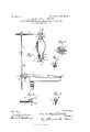
- Figure l is a side elevation, partly in section, of our device and a cut-away portion of a table or other suitable support to which it is adapted to be applied.
- Fig. 2 is a horizontal section on the line a: .r of Fig. 1.
- Figs. 3, 4, and 5 are detailed views, respectively, of the air-regulating cap, the flask or receptacle clamp, and socket for receiving the flask or receptacle clamp-supporting arm.
- A represents'a flask or receptacle provided externally at its lower or outlet end with screw-threads. Fitted in its upper end is a cork B, through which extends a tube C. Threaded on the upper end of the tube C is a cap D. (Shown clearly in Fig. 3.) Graduated air-openings a are formed in the side of the cap D, so that by turning the same more or less a larger or smaller opening is exposed and a corresponding amount of air admitted to the flask or receptacle, thereby displacing the fluid more or less quickly.
- E is an internally-threaded cap engaging the lower or discharge end of the flask and having a contracted neck portion F. Seated on the end of said bottle is a rubber disk II, which has a tubular extension I fitting inside the neck F.
- K is a clamp engaging the tubular extension I for the purpose of shutting off the flow by compressing said tubular extension and the wick contained therein and. about to be described.
- the clamp K comprises a substantially U-shaped member having an adjusting-screw swiveled to the bottom thereof and pnjijecting through and engaging a threaded opening in the neck F. Bearing against the tube I on the opposite side from which the clamp engages the same is a segmental block M, secured to the inside of the neck F and conforming to the surface of tube not otherwise engaged.
- the block M and the clamp cooperate to obtain an even pressure on all sides of the rubber tube I, which is compressed when the clamp is forced against the same, and thereby tend to 0011- tract a wick N, extending through the disk and its tubular extension.
- Primary regulation of the wick is obtained by screwing down the cap E until the disk is forced hard against the end of the flask, by which the disk and its tubular extension are compressed.
- the discharge of the fluid may be regulated, first, by adjusting the air-supply by means of cap E; further, by contracting wick N, which conveys the fluid outwardly through the medium of cap E and disk H, and finally by operating the clamp K to choke the wick N still further and prevent the discharge of fluid entirely when desired.
- the flask just described is supported in the clamp shown in Fig. 4, which is rigidly secured to the supporting-arm O and coinprises a rigid arm b and a hinged arm a.
- the clamp may be regulated by an adjustingscrew (Z.
- the arm 0 is an elongated bar provided centrally on both sides with flanges, the same engaging a complementary socket P at the extremity of an upright
- This bar and socket may be of any other convenient shape, the purpose being to prevent rotation of the arm 0, which is held in position by a screw 6 or the like.
- R is a second upright pivotally secured to the bar Q and held in adjusted position by any suitable means, as a thumb-screw q.
- the upright R extends through and is secured in a vertically-extending opening in an offset portion of a clamping member S by a thumb-screw or other holding means the rod fitting loosely within said opening, wherestand and lock the clamp against any except a lateral movement relative to the table.
- the construction described provides for an adjustment of the flask-support along the table, a second adjustment annularly relative thereto, and a third adjustment to and from said table, so that the flask may be placed and securely held in any position whatsoever relative to the stand upon which it is being used.
- the construction and arrangement of the parts having been set forth, the operation of our improved device is as follows:
- the receptacle is adjusted to the desired position, after which the air-regulating cap is turned according to the amount of air desired to be admitted. This gives partial'regulation to the discharge of the fluid. Further adjustment is obtained by forcing the cap on the discharge end closer to the receptacle itself, after which the flow may be decreased still more or cut off entirely by operating the clamp K.
- a device of the character described including a receptacle having a contracted portion at one end thereof, a wick extending through said contracted portion, and means for compressing said Wick.
- a device of the character described including a receptacle havin a contracted portion at one end thereof, a exible tube Within said contracted portion, a wick extending through said tube, and means for compressing said wick.
- a device of the character described including a receptacle, a tube projecting therefrom, a cap having threaded engagement with said tube, and graduated openings in the side of said cap.
- a device of the character described includin a receptacle threaded at one end thereof, a cap engaging said threaded portion, and provided with a contracted neck, a Wick extending through said neck, and means for compressing said wick.
- a device of the character described includin a receptacle threaded at one end thereo a cap engaging said end and provided with a contracted neck, a tube within said neck, a wick extending through said In the bearing-surface of tube, and means for compressing said tube around said neck.
- a device of the character described includin a receptacle, threaded at one end thereof, a cap engaging said threaded portion and provided with a contracted neck, a rubber tube Within said neck, a wick extending through said tube, and means for compressing said tube around said Wick.
- a receptacle threaded at one end thereof, a cap engaging said threaded portion, and having a contracted neck, a wick extending through said neck, in combination with a substantially U-shaped clamp engaging said wick, the arms thereof working in openings in the before-mentioned neck.
- a receptacle threaded externally at one end, a cap engaging said threaded portion, andprovided with'a contracted neck, a disk supported in said cap having a central opening therein, a tubular extension on said disk surrounding said opening and fitting Within said neck, a Wick extending through said neck, in combination with means for compressing the tube and disk around said wick.
- a receptacle threaded at one end, a cap engaging said threaded portion and provided with acontracted neck, a segmental block secured within said neck and engaging a flexible tube fitting therein, a clamping member engaging said tube and cooperating with said segmental block to compress the same.
- a device of the character described including a flask or receptacle threaded at one end, a cork fitting within the other end,
- a tube extending through said cork, a cap provided with graduated openings and having threaded engagement with the extremity of said tube, a second cap engaging said threaded portion of the flask or receptacle and having a contracted neck, a flexible tube therewithin, a wick extending through said tube, and means for compressing said tube around said wick.
- a device of the character described including a receptacle, a Wick extending therefrom, and means for regulating the discharge of fluid through said wick, said means including a compressor for the wick.
Landscapes
- Health & Medical Sciences (AREA)
- Anesthesiology (AREA)
- Emergency Medicine (AREA)
- Pulmonology (AREA)
- Engineering & Computer Science (AREA)
- Biomedical Technology (AREA)
- Heart & Thoracic Surgery (AREA)
- Hematology (AREA)
- Life Sciences & Earth Sciences (AREA)
- Animal Behavior & Ethology (AREA)
- General Health & Medical Sciences (AREA)
- Public Health (AREA)
- Veterinary Medicine (AREA)
- Loading And Unloading Of Fuel Tanks Or Ships (AREA)
Description
No. 831,728. v PATENTED SEPT. 25, 1906. J. R. MAXFIELD & S. B. MAUPIN. ANESTHETIG HOLDING AND DISPENSING APPARATUS.
APPLICATION FILED FEB. S, 1906.
UNITED STATEE% FATIINT OFFIC.
JAMES R. MAXFIELD AND SETH B. MAUPIN, OF GRAND SALINE, TEXAS.
ANESTHETIC HOLDING AND DISPENSING APPARATUS.
Specification of Letters Patent.
Patented Sept. 25, 1906.
Application filed February 3, 1906. Serial No. 299,322.
To LZZ whom it may concern:
Be it known that we, JAMEs R. MAxFIELn and SETH B. MAUPIN, citizens of the United $tates, residing at Grand Saline, in the county of Van Zandt and State of Texas, have in vented certain new and useful Improvements in Anesthetic Holding and Dispensing Apparatus, of which the following is a specification, reference being had therein to the accompanying drawings.
The invention relates to that class of devices which are employed in surgical operations or the like where it is necessary to administer anesthetics and desirable to have the holder vertically, laterally, and angularly adjustably secured to the operating-table and so constructed as to permit of the perfect control of the outward passage of the fluid.
Briefly stated, the invention contemplates a flask or receptacle so constructed as to permit of regulating the discharge of fluid therefrom and the entrance of air thereto, to-' gether with means for holding the receptacle in any position relative to a supporting stand or table.
In the drawings, Figure l is a side elevation, partly in section, of our device and a cut-away portion of a table or other suitable support to which it is adapted to be applied. Fig. 2 is a horizontal section on the line a: .r of Fig. 1. Figs. 3, 4, and 5 are detailed views, respectively, of the air-regulating cap, the flask or receptacle clamp, and socket for receiving the flask or receptacle clamp-supporting arm.
Referring more specifically to the drawings, in which like reference characters refer to corresponding parts in the several views, A represents'a flask or receptacle provided externally at its lower or outlet end with screw-threads. Fitted in its upper end is a cork B, through which extends a tube C. Threaded on the upper end of the tube C is a cap D. (Shown clearly in Fig. 3.) Graduated air-openings a are formed in the side of the cap D, so that by turning the same more or less a larger or smaller opening is exposed and a corresponding amount of air admitted to the flask or receptacle, thereby displacing the fluid more or less quickly.
E is an internally-threaded cap engaging the lower or discharge end of the flask and having a contracted neck portion F. Seated on the end of said bottle is a rubber disk II, which has a tubular extension I fitting inside the neck F. K is a clamp engaging the tubular extension I for the purpose of shutting off the flow by compressing said tubular extension and the wick contained therein and. about to be described. The clamp K comprises a substantially U-shaped member having an adjusting-screw swiveled to the bottom thereof and pnjijecting through and engaging a threaded opening in the neck F. Bearing against the tube I on the opposite side from which the clamp engages the same is a segmental block M, secured to the inside of the neck F and conforming to the surface of tube not otherwise engaged. The block M and the clamp cooperate to obtain an even pressure on all sides of the rubber tube I, which is compressed when the clamp is forced against the same, and thereby tend to 0011- tract a wick N, extending through the disk and its tubular extension. Primary regulation of the wick is obtained by screwing down the cap E until the disk is forced hard against the end of the flask, by which the disk and its tubular extension are compressed.
It will be clearly seen that the discharge of the fluid may be regulated, first, by adjusting the air-supply by means of cap E; further, by contracting wick N, which conveys the fluid outwardly through the medium of cap E and disk H, and finally by operating the clamp K to choke the wick N still further and prevent the discharge of fluid entirely when desired.
The flask just described is supported in the clamp shown in Fig. 4, which is rigidly secured to the supporting-arm O and coinprises a rigid arm b and a hinged arm a. The clamp may be regulated by an adjustingscrew (Z.
The arm 0 is an elongated bar provided centrally on both sides with flanges, the same engaging a complementary socket P at the extremity of an upright This bar and socket, however, may be of any other convenient shape, the purpose being to prevent rotation of the arm 0, which is held in position by a screw 6 or the like.
R is a second upright pivotally secured to the bar Q and held in adjusted position by any suitable means, as a thumb-screw q. The upright R extends through and is secured in a vertically-extending opening in an offset portion of a clamping member S by a thumb-screw or other holding means the rod fitting loosely within said opening, wherestand and lock the clamp against any except a lateral movement relative to the table.
The construction described provides for an adjustment of the flask-support along the table, a second adjustment annularly relative thereto, and a third adjustment to and from said table, so that the flask may be placed and securely held in any position whatsoever relative to the stand upon which it is being used.
The construction and arrangement of the parts having been set forth, the operation of our improved device is as follows: The receptacle is adjusted to the desired position, after which the air-regulating cap is turned according to the amount of air desired to be admitted. This gives partial'regulation to the discharge of the fluid. Further adjustment is obtained by forcing the cap on the discharge end closer to the receptacle itself, after which the flow may be decreased still more or cut off entirely by operating the clamp K.
What we claim is- 1. A device of the character described, including a receptacle having a contracted portion at one end thereof, a wick extending through said contracted portion, and means for compressing said Wick.
2. A device of the character described, including a receptacle havin a contracted portion at one end thereof, a exible tube Within said contracted portion, a wick extending through said tube, and means for compressing said wick.
3. A device of the character described, including a receptacle, a tube projecting therefrom, a cap having threaded engagement with said tube, and graduated openings in the side of said cap.
4. A device of the character described, includin a receptacle threaded at one end thereof, a cap engaging said threaded portion, and provided with a contracted neck, a Wick extending through said neck, and means for compressing said wick.
5. A device of the character described, includin a receptacle threaded at one end thereo a cap engaging said end and provided with a contracted neck, a tube within said neck, a wick extending through said In the bearing-surface of tube, and means for compressing said tube around said neck.
6. A device of the character described, includin a receptacle, threaded at one end thereof, a cap engaging said threaded portion and provided with a contracted neck, a rubber tube Within said neck, a wick extending through said tube, and means for compressing said tube around said Wick.
7. In a device of the character described, a receptacle threaded at one end thereof, a cap engaging said threaded portion, and having a contracted neck, a wick extending through said neck, in combination with a substantially U-shaped clamp engaging said wick, the arms thereof working in openings in the before-mentioned neck.
8. In a device of the character described, .a receptacle threaded externally at one end, a cap engaging said threaded portion, andprovided with'a contracted neck, a disk supported in said cap having a central opening therein, a tubular extension on said disk surrounding said opening and fitting Within said neck, a Wick extending through said neck, in combination with means for compressing the tube and disk around said wick.
9. In a device of the character described, a receptacle threaded at one end, a cap engaging said threaded portion and provided with acontracted neck, a segmental block secured within said neck and engaging a flexible tube fitting therein, a clamping member engaging said tube and cooperating with said segmental block to compress the same.
10. A device of the character described, including a flask or receptacle threaded at one end, a cork fitting within the other end,
a tube extending through said cork, a cap provided with graduated openings and having threaded engagement with the extremity of said tube, a second cap engaging said threaded portion of the flask or receptacle and having a contracted neck, a flexible tube therewithin, a wick extending through said tube, and means for compressing said tube around said wick.
11. A device of the character described, including a receptacle, a Wick extending therefrom, and means for regulating the discharge of fluid through said wick, said means including a compressor for the wick.
In testimony whereof we affix our signatures in presence of two Witnesses.
JAMES R. MAXFIELD. SETH B. MAUPIN. Witnesses:
I. K. GRooMs, C. B. SMITH.
IIO
Priority Applications (1)
| Application Number | Priority Date | Filing Date | Title |
|---|---|---|---|
| US29932206A US831728A (en) | 1906-02-03 | 1906-02-03 | Anesthetic holding and dispensing apparatus. |
Applications Claiming Priority (1)
| Application Number | Priority Date | Filing Date | Title |
|---|---|---|---|
| US29932206A US831728A (en) | 1906-02-03 | 1906-02-03 | Anesthetic holding and dispensing apparatus. |
Publications (1)
| Publication Number | Publication Date |
|---|---|
| US831728A true US831728A (en) | 1906-09-25 |
Family
ID=2900203
Family Applications (1)
| Application Number | Title | Priority Date | Filing Date |
|---|---|---|---|
| US29932206A Expired - Lifetime US831728A (en) | 1906-02-03 | 1906-02-03 | Anesthetic holding and dispensing apparatus. |
Country Status (1)
| Country | Link |
|---|---|
| US (1) | US831728A (en) |
Cited By (2)
| Publication number | Priority date | Publication date | Assignee | Title |
|---|---|---|---|---|
| US2963247A (en) * | 1960-01-11 | 1960-12-06 | George L Collier | Support for anaesthesia applier |
| US20110155766A1 (en) * | 2009-12-28 | 2011-06-30 | Hurley Timothy R | Mountable hand sanitizer station |
-
1906
- 1906-02-03 US US29932206A patent/US831728A/en not_active Expired - Lifetime
Cited By (2)
| Publication number | Priority date | Publication date | Assignee | Title |
|---|---|---|---|---|
| US2963247A (en) * | 1960-01-11 | 1960-12-06 | George L Collier | Support for anaesthesia applier |
| US20110155766A1 (en) * | 2009-12-28 | 2011-06-30 | Hurley Timothy R | Mountable hand sanitizer station |
Similar Documents
| Publication | Publication Date | Title |
|---|---|---|
| US688230A (en) | Adjustable holder for embroidery-hoops. | |
| US1228083A (en) | Copy-holder. | |
| US618324A (en) | Dental plugger | |
| US1001805A (en) | Beer-preserver. | |
| US1067780A (en) | Distributer. | |
| US169735A (en) | Improvement in inkstands | |
| US571692A (en) | Joseph schneible | |
| US560092A (en) | Support for blowpipes | |
| US825173A (en) | Apparatus for siphoning liquids from bottles. | |
| US340778A (en) | gilbert | |
| US953407A (en) | Device for temporarily maintaining a fixed point or center on plane surfaces. | |
| US672104A (en) | Apparatus for setting rubber tires. | |
| US502991A (en) | phillips | |
| US643981A (en) | Apparatus for use in writing by hand. | |
| US111782A (en) | Improvement in sewing-machine seats | |
| US77286A (en) | Charles hodge hudson | |
| US1224515A (en) | Combined clamp and support. | |
| US953565A (en) | Press. | |
| US600395A (en) | Portable foot-support | |
| US749815A (en) | E korris peters co | |
| US1033861A (en) | Acetylene-gas lamp. | |
| US684001A (en) | Bicycle-pump. | |
| US649717A (en) | Gas-administering apparatus. | |
| US726621A (en) | Corking apparatus. | |
| US754951A (en) | Bottle-filling apparatus. |