US8317128B2 - Laminar flow wing optimized for transonic cruise aircraft - Google Patents
Laminar flow wing optimized for transonic cruise aircraft Download PDFInfo
- Publication number
- US8317128B2 US8317128B2 US12/932,091 US93209111A US8317128B2 US 8317128 B2 US8317128 B2 US 8317128B2 US 93209111 A US93209111 A US 93209111A US 8317128 B2 US8317128 B2 US 8317128B2
- Authority
- US
- United States
- Prior art keywords
- wing
- aircraft
- fuselage
- degrees
- drag
- Prior art date
- Legal status (The legal status is an assumption and is not a legal conclusion. Google has not performed a legal analysis and makes no representation as to the accuracy of the status listed.)
- Expired - Fee Related, expires
Links
Images


Classifications
-
- B—PERFORMING OPERATIONS; TRANSPORTING
- B64—AIRCRAFT; AVIATION; COSMONAUTICS
- B64C—AEROPLANES; HELICOPTERS
- B64C3/00—Wings
- B64C3/10—Shape of wings
-
- B—PERFORMING OPERATIONS; TRANSPORTING
- B64—AIRCRAFT; AVIATION; COSMONAUTICS
- B64C—AEROPLANES; HELICOPTERS
- B64C3/00—Wings
- B64C3/10—Shape of wings
- B64C3/14—Aerofoil profile
-
- B—PERFORMING OPERATIONS; TRANSPORTING
- B64—AIRCRAFT; AVIATION; COSMONAUTICS
- B64C—AEROPLANES; HELICOPTERS
- B64C30/00—Supersonic type aircraft
-
- Y—GENERAL TAGGING OF NEW TECHNOLOGICAL DEVELOPMENTS; GENERAL TAGGING OF CROSS-SECTIONAL TECHNOLOGIES SPANNING OVER SEVERAL SECTIONS OF THE IPC; TECHNICAL SUBJECTS COVERED BY FORMER USPC CROSS-REFERENCE ART COLLECTIONS [XRACs] AND DIGESTS
- Y02—TECHNOLOGIES OR APPLICATIONS FOR MITIGATION OR ADAPTATION AGAINST CLIMATE CHANGE
- Y02T—CLIMATE CHANGE MITIGATION TECHNOLOGIES RELATED TO TRANSPORTATION
- Y02T50/00—Aeronautics or air transport
- Y02T50/10—Drag reduction
Definitions
- This invention relates generally to the configuration of transonic aircraft with wings designed for extensive natural laminar flow (NLF), and more particularly to optimization of wing thickness, sweep and fuselage cross section relationship criteria, for such transonic aircraft.
- NNF natural laminar flow
- Transonic NLF wing aircraft configurations as described herein are desirable for efficient transonic cruise, e.g. high subsonic speeds typically above about Mach 0.80 and up to slightly above Mach 1.
- Principal features of the herein described configurations are low to moderate sweep, sharp or slightly blunted leading edge, and relatively thin airfoils in terms of the ratio of maximum airfoil thickness to chord (t/c).
- the importance of the NLF boundary layer (BL) in terms of drag reduction can be understood by considering that for typical transonic cruise flight conditions the laminar skin friction drag is approximately 10% of the turbulent skin friction drag associated with a traditional swept wing designs, for the same amount of surface area.
- the transonic NLF wing configurations described herein can achieve best cruise efficiency at higher Mach numbers than possible with the swept wings typically used on high speed subsonic cruise aircraft.
- the wing For extensive NLF, the wing must have low or moderate sweep, and thus, on a purely aerodynamic basis the low sweep NLF wing should be relatively thin to limit the volume wave drag at the design cruise Mach number. On the other hand a thinner wing incurs a weight penalty, since structural weight varies inversely with wing thickness, everything else being equal, so that selection of thickness to chord ratio (t/c) is of substantial importance to optimizing the performance of such aircraft.
- certain design combinations of wing sweep and t/c can enable efficient cruise Mach numbers up to about 1.05, well beyond the maximum efficient cruise Mach number of high speed, long range aircraft other than supersonic designs capable of operating at more than about Mach 1.2.
- Such wings were found to require average t/c ratios of about 0.03 (3%) or less, and for some missions could benefit from greater leading edge sweep than the previous limit of about 20 degrees specified in our U.S. Pat. No. 7,000,870.
- a sweep of about 30 degrees is required for an efficient cruise Mach number of 0.99 with an average t/c ratio of about 0.03 (3%). Achieving extensive NLF for such wing sweep is more difficult and some loss in LF coverage extent is inevitable.
- the achievement of NLF on large areas of the wing surface is dependent on (a) achieving appropriate pressure gradients over the affected surfaces of the wing and (b) suitable leading edge size and shape.
- These pressure gradients depend not only on the local airfoil shapes, but also are influenced by the fuselage contour or contours adjacent to the wing.
- the present invention extends the use of wing configurations for aircraft designed for efficient cruise at transonic speed, described in prior U.S. Pat. No. 7,000,870, “LAMINAR FLOW WING FOR TRANSONIC CRUISE” and in patent application Ser. No.
- the wing thickness to chord ratios may typically vary from outboard of the zone of substantial fuselage influence to the wing tip, such that the average of such ratio along such portion of the span is consistent with the criteria stated in the foregoing.
- Wing sweep refers to the leading edge of the basic “trapezoidal wing”, or to the minimum leading edge sweep in other cases such as the “ogive” wing plan or wings with an inboard strake.
- the invention includes all airfoil types such as bi-convex, NACA 6-series and supercritical, appropriately modified to provide, at design cruise Mach number and lift coefficient, an optimal combination of (a) extensive laminar flow over upper, lower, or both surfaces, (b) low wave drag, and also (c) high lift at low speed.
- the fuselage is preferably contoured to reduce or minimize wave drag of the wing-fuselage combination, including engine nacelles and empennage.
- the foregoing principals generally apply to tail surfaces as well.
- Such wing and fuselage contours to achieve optimal mission performance can be accomplished by either (a) an iterative process combining configuration design experience, aerodynamic analysis and wind tunnel testing, or (b) a computer-based multi-disciplinary optimization method combined with configuration design constraints.
- the foregoing design processes also would preferably include propulsion nacelles and tail or other lifting or control surfaces such as canards.
- the shaping optimization also would preferably include the effect of the distribution of t/c on wing weight and thus on range at a given overall maximum weight or maximum weight for a given range.
- FIG. 1 shows such an aircraft in plan view, as well as a cross section of the wing showing a typical airfoil in FIG. 1 a.
- FIG. 2 shows a representative transonic aircraft configuration
- FIG. 3 is a graph of the pressures on the upper and lower surfaces of an airfoil at two Mach numbers.
- FIG. 4 is a graph showing a relationship between airfoil t/c and drag-rise Mach number.
- FIG. 5 is a graph showing the drag of a wing-fuselage configuration with 3% average wing t/c.
- FIG. 6 is a graph of showing higher critical Mach number as a function of wing leading edge sweep.
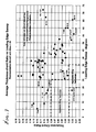
- FIG. 7 is a chart showing the combination of wing sweep and t/c ratio for various representative aircraft.
- FIG. 1 shows an aircraft 9 incorporating the invention including a fuselage 5 , a jet engine nacelle 6 including inlet and exhaust ends 6 a and 6 b , tail 7 and wing 1 .
- An integrated fuselage/nacelle is illustrated, but the invention applies also to aircraft with separate engine nacelles mounted on the wing or fuselage.
- the wing leading edge sweep angle ⁇ is defined as the minimum angle of the outboard trapezoidal wing leading edge 2 relative to a line projected normally outboard from the aircraft longitudinal axis.
- FIG. 1 a is a chordwise vertical section A-A through the wing 8 , and is generally representative of the wing t/c ratio, where these dimensions are shown in section A-A.
- the wing t/c is defined as the average of the t/c values along the wing span from a location outboard of the zone of appreciable fuselage influence on wing drag to the wing tip 4 .
- Location 11 shows a reduction in cross-sectional area of the fuselage and/or nacelle adjacent to wing 1 to reduce wave drag in accordance with area rule principals, as well as to reduce viscous drag by suppressing cross-flow pressure gradients across the wing surface, which are generally adverse to laminar flow.
- Location 12 shows a similar modification of fuselage cross-sectional area adjacent to tail 7 .
- FIG. 2 shows an alternative preferred aircraft configuration 20 incorporating the invention, featuring a fuselage body 22 , engine nacelle 23 , wing 21 , aft located horizontal tail surface 24 , aft located vertical tail surface 26 , and forwardly located canard surface 25 .
- Any or all of the wing and stabilizing or control surfaces 21 , 24 , 25 , 26 may incorporate leading edge sweep and thickness geometries as described previously.
- the fuselage 22 and/or nacelle 23 may have reduced cross-section or “waisting” adjacent to surfaces 21 , 24 , 25 , or 26 to reduce drag as described above.
- FIG. 3 illustrates the pressures on the upper and lower surfaces of an airfoil at two Mach numbers. It shows the effect of higher subsonic Mach number in creating pressure conditions favorable to laminar flow, namely the negative pressure gradients (pressure decreasing with distance aft) over the majority of both upper and lower surfaces at Mach 0.95. For comparison the positive pressure gradients at Mach 0.8, especially on the upper surface, are adverse to extensive runs of laminar flow.
- FIG. 4 is a graph showing a representative relationship between airfoil t/c and the drag divergence Mach number (Mdd), for which the increase in drag coefficient is 0.002.
- the data is calculated using high order aerodynamic codes able to correctly represent conditions near Mach 1.
- the airfoils for this example are sharp-edged bi-convex sections at zero lift, and thus represent the lowest drag at a given Mach number and t/c. Airfoils with blunt leading edges, camber and angle of attack corresponding to a representative cruise lift coefficient will have a somewhat lower drag divergence Mach number, but the graph is illustrative of the relationship of Mdd to t/c.
- FIG. 5 illustrates the relatively low drag-rise at high subsonic Mach number of a wing-fuselage configuration with 3% average wing t/c, both at zero lift and at a lift coefficient of 0.3, typical of transonic cruise conditions.
- the drag divergence Mach number occurs at about Mach 0.96, much higher than achieved to applicants' knowledge with any current conventional swept wing subsonic aircraft.
- FIG. 6 shows the approximate increase in critical Mach number (a widely used criterion for incipient drag rise with increasing Mach number) as a function of quarter-chord sweep for wings typical of those used in industry.
- This curve can be considered a first-order estimate of the role of leading edge sweep in increasing the low drag Mach number for a given t/c and airfoil.
- a sweep angle of 30 degrees should increase Mdd by about 0.06.
- an unswept wing with 3% t/c would have an Mdd of about 0.93, thus the 30 degree swept wing with 3% t/c would be expected to achieve efficient low drag flight at about Mach 0.99.
- This result would vary depending on details of the airfoil, wing span and integration with a fuselage, but is a much higher drag rise Mach number than can achieved to applicants' knowledge with any conventional 30 degree swept wing.
- FIG. 7 is a chart showing the combination of wing sweep and wing t/c ratio for all representative aircraft with maximum operating cruise speeds, Mmo, of more than Mach 0.80. Only selected points are identified as to the specific aircraft models to reduce clutter and emphasize known aircraft.
- the chart shows that all aircraft with wing sweep angles below about 25 degrees, have thicker wings than the proposed 8% t/c upper limit.
- subsonic aircraft such as jet transports and high end business jets designed for Mmo greater than Mach 0.80, but none having wing sweep less than 20 degrees and t/c below 8%.
- supersonic aircraft mainly fighters, designed for Mmo up to Mach 2 or more, employing average t/c greater than about 0.03, but with wing sweep well above 20 degrees.
- FIG. 7 indicates, there are no aircraft that embody the proposed configuration combinations, namely (a) leading edge sweep less than about 25 degrees combined with average t/c between about 3% and 8%, and (b) leading edge sweep between about 20 and 35 degrees combined with average t/c less than about 0.03 (3%).
Landscapes
- Engineering & Computer Science (AREA)
- Aviation & Aerospace Engineering (AREA)
- Mechanical Engineering (AREA)
- Aerodynamic Tests, Hydrodynamic Tests, Wind Tunnels, And Water Tanks (AREA)
Abstract
Description
Claims (15)
Priority Applications (3)
| Application Number | Priority Date | Filing Date | Title |
|---|---|---|---|
| US12/932,091 US8317128B2 (en) | 2009-10-26 | 2011-02-16 | Laminar flow wing optimized for transonic cruise aircraft |
| EP12746945.0A EP2675706A4 (en) | 2011-02-16 | 2012-02-13 | Laminar flow wing optimized for transonic cruise aircraft |
| PCT/US2012/024794 WO2012112408A1 (en) | 2011-02-16 | 2012-02-13 | Laminar flow wing optimized for transonic cruise aircraft |
Applications Claiming Priority (2)
| Application Number | Priority Date | Filing Date | Title |
|---|---|---|---|
| US12/589,424 US8272594B2 (en) | 2009-10-26 | 2009-10-26 | Laminar flow wing optimized for supersonic cruise aircraft |
| US12/932,091 US8317128B2 (en) | 2009-10-26 | 2011-02-16 | Laminar flow wing optimized for transonic cruise aircraft |
Related Parent Applications (1)
| Application Number | Title | Priority Date | Filing Date |
|---|---|---|---|
| US12/589,424 Continuation-In-Part US8272594B2 (en) | 2009-10-26 | 2009-10-26 | Laminar flow wing optimized for supersonic cruise aircraft |
Publications (2)
| Publication Number | Publication Date |
|---|---|
| US20120043430A1 US20120043430A1 (en) | 2012-02-23 |
| US8317128B2 true US8317128B2 (en) | 2012-11-27 |
Family
ID=46672894
Family Applications (1)
| Application Number | Title | Priority Date | Filing Date |
|---|---|---|---|
| US12/932,091 Expired - Fee Related US8317128B2 (en) | 2009-10-26 | 2011-02-16 | Laminar flow wing optimized for transonic cruise aircraft |
Country Status (3)
| Country | Link |
|---|---|
| US (1) | US8317128B2 (en) |
| EP (1) | EP2675706A4 (en) |
| WO (1) | WO2012112408A1 (en) |
Cited By (2)
| Publication number | Priority date | Publication date | Assignee | Title |
|---|---|---|---|---|
| US20140131511A1 (en) * | 2012-07-16 | 2014-05-15 | Airbus Operations S.L. | Aircraft lifting surface with variable sweep distribution along the span |
| RU2540293C1 (en) * | 2013-08-14 | 2015-02-10 | Федеральное государственное унитарное предприятие "Центральный аэрогидродинамический институт имени профессора Н.Е. Жуковского" (ФГУП "ЦАГИ") | Aircraft wing |
Families Citing this family (10)
| Publication number | Priority date | Publication date | Assignee | Title |
|---|---|---|---|---|
| CN104229122B (en) * | 2014-10-08 | 2017-02-22 | 朱晓义 | aircraft |
| FR3101853B1 (en) * | 2019-10-15 | 2022-04-29 | Safran Nacelles | AIRPLANE WITH OFFSET NACELLE FLUSH WITH THE WAKE WAKE |
| DE102019129998B4 (en) * | 2019-11-07 | 2022-04-28 | Deutsches Zentrum für Luft- und Raumfahrt e.V. | Aircraft with jet engines above the wings and with a local extension of the fuselage to reduce aerodynamic drag at transonic flight speeds |
| CN111159815B (en) * | 2019-12-24 | 2023-05-23 | 中国航空工业集团公司西安飞机设计研究所 | A fast optimization method for aircraft wing plane parameters |
| CN112572788A (en) * | 2020-12-04 | 2021-03-30 | 中国航空工业集团公司成都飞机设计研究所 | Aircraft with cross-over supersonic pneumatic performance |
| EP4011760A1 (en) * | 2020-12-10 | 2022-06-15 | Ernst Heinrich Hirschel | Swept quasi-thin supercritical laminar wing |
| CN113962025B (en) * | 2021-10-26 | 2024-05-14 | 成都飞机工业(集团)有限责任公司 | Wing section optimization method and device for ultra-flat tail-free supersonic aircraft |
| CN115688434A (en) * | 2022-11-03 | 2023-02-03 | 中国航空工业集团公司沈阳空气动力研究所 | A method for optimal design of supersonic wing laminar flow |
| CN117910150B (en) * | 2024-03-20 | 2024-05-31 | 西北工业大学 | A method and system for designing a transonic airfoil profile of an aircraft swept wing |
| CN120270530B (en) * | 2025-06-09 | 2025-08-05 | 西北工业大学 | Wing body fusion wide-speed-range aircraft layout design method based on considering back body effect |
Citations (8)
| Publication number | Priority date | Publication date | Assignee | Title |
|---|---|---|---|---|
| US2709052A (en) * | 1952-04-15 | 1955-05-24 | Charles J Fletcher | Spanwise flow control of fluid swept lifting surfaces |
| US4611773A (en) * | 1982-12-30 | 1986-09-16 | The Boeing Company | Tapered thickness-chord ratio wing |
| US4834617A (en) * | 1987-09-03 | 1989-05-30 | United Technologies Corporation | Airfoiled blade |
| JPH01141199A (en) | 1987-09-03 | 1989-06-02 | United Technol Corp <Utc> | Propeller wing |
| US5322242A (en) * | 1991-07-08 | 1994-06-21 | Tracy Richard R | High efficiency, supersonic aircraft |
| US5897076A (en) * | 1991-07-08 | 1999-04-27 | Tracy; Richard R. | High-efficiency, supersonic aircraft |
| US6149101A (en) * | 1991-07-08 | 2000-11-21 | Tracy; Richard R. | Aircraft wing and fuselage contours |
| US7000870B2 (en) * | 2002-11-07 | 2006-02-21 | Aerion Corporation | Laminar flow wing for transonic cruise |
Family Cites Families (6)
| Publication number | Priority date | Publication date | Assignee | Title |
|---|---|---|---|---|
| US4828204A (en) * | 1979-08-13 | 1989-05-09 | The Boeing Company | Supersonic airplane |
| JP2633413B2 (en) * | 1991-06-03 | 1997-07-23 | 富士重工業株式会社 | Rotor blades of rotary wing aircraft |
| US7946535B2 (en) * | 2006-10-18 | 2011-05-24 | Aerion Corporation | Highly efficient supersonic laminar flow wing |
| US8113462B2 (en) * | 2007-01-08 | 2012-02-14 | Israel Aerospace Industries, Ltd. | Low-drag swept wings |
| US8272594B2 (en) * | 2009-10-26 | 2012-09-25 | Aerion Corporation | Laminar flow wing optimized for supersonic cruise aircraft |
| US8448893B2 (en) * | 2009-10-26 | 2013-05-28 | Aerion Corporation | Laminar flow wing optimized for transonic cruise aircraft |
-
2011
- 2011-02-16 US US12/932,091 patent/US8317128B2/en not_active Expired - Fee Related
-
2012
- 2012-02-13 WO PCT/US2012/024794 patent/WO2012112408A1/en not_active Ceased
- 2012-02-13 EP EP12746945.0A patent/EP2675706A4/en not_active Ceased
Patent Citations (9)
| Publication number | Priority date | Publication date | Assignee | Title |
|---|---|---|---|---|
| US2709052A (en) * | 1952-04-15 | 1955-05-24 | Charles J Fletcher | Spanwise flow control of fluid swept lifting surfaces |
| US4611773A (en) * | 1982-12-30 | 1986-09-16 | The Boeing Company | Tapered thickness-chord ratio wing |
| US4834617A (en) * | 1987-09-03 | 1989-05-30 | United Technologies Corporation | Airfoiled blade |
| JPH01141199A (en) | 1987-09-03 | 1989-06-02 | United Technol Corp <Utc> | Propeller wing |
| US5322242A (en) * | 1991-07-08 | 1994-06-21 | Tracy Richard R | High efficiency, supersonic aircraft |
| US5518204A (en) * | 1991-07-08 | 1996-05-21 | Tracy; Richard R. | High-efficiency, supersonic aircraft |
| US5897076A (en) * | 1991-07-08 | 1999-04-27 | Tracy; Richard R. | High-efficiency, supersonic aircraft |
| US6149101A (en) * | 1991-07-08 | 2000-11-21 | Tracy; Richard R. | Aircraft wing and fuselage contours |
| US7000870B2 (en) * | 2002-11-07 | 2006-02-21 | Aerion Corporation | Laminar flow wing for transonic cruise |
Non-Patent Citations (1)
| Title |
|---|
| Peter Sturdza, Valerie M. Manning, Ilan M. Kroo, Richard R. Tracy, "Boundary Layer Calculations Preliminary Design of Wings in Supersonic Flow", American Institute of Aeronautics and Astronautics, pp. 1-11, USA. |
Cited By (3)
| Publication number | Priority date | Publication date | Assignee | Title |
|---|---|---|---|---|
| US20140131511A1 (en) * | 2012-07-16 | 2014-05-15 | Airbus Operations S.L. | Aircraft lifting surface with variable sweep distribution along the span |
| US9718534B2 (en) * | 2012-07-16 | 2017-08-01 | Airbus Operations S.L. | Aircraft lifting surface with variable sweep distribution along the span |
| RU2540293C1 (en) * | 2013-08-14 | 2015-02-10 | Федеральное государственное унитарное предприятие "Центральный аэрогидродинамический институт имени профессора Н.Е. Жуковского" (ФГУП "ЦАГИ") | Aircraft wing |
Also Published As
| Publication number | Publication date |
|---|---|
| US20120043430A1 (en) | 2012-02-23 |
| EP2675706A4 (en) | 2017-09-27 |
| EP2675706A1 (en) | 2013-12-25 |
| WO2012112408A1 (en) | 2012-08-23 |
Similar Documents
| Publication | Publication Date | Title |
|---|---|---|
| US8317128B2 (en) | Laminar flow wing optimized for transonic cruise aircraft | |
| US6578798B1 (en) | Airlifting surface division | |
| US4828204A (en) | Supersonic airplane | |
| US8448893B2 (en) | Laminar flow wing optimized for transonic cruise aircraft | |
| US6293497B1 (en) | Airplane with unswept slotted cruise wing airfoil | |
| CA2372166C (en) | Aircraft wing and fuselage contours | |
| US5322242A (en) | High efficiency, supersonic aircraft | |
| CN102666275B (en) | A method of providing an aircraft having a fuselage and a wing and aircraft made thereby | |
| US8113462B2 (en) | Low-drag swept wings | |
| US10625847B2 (en) | Split winglet | |
| WO1998017529A9 (en) | Airplane with unswept slotted cruise wing airfoil | |
| CA2713363A1 (en) | Aerodynamic structure with series of shock bumps | |
| US5901925A (en) | Serrated-planform lifting-surfaces | |
| US20040094659A1 (en) | Laminar-flow airfoil | |
| EP3560825B1 (en) | An aircraft wing and wing tip device | |
| Nelson | Effects of wing planform on HSCT off-design aerodynamics | |
| EP0103478A1 (en) | Airfoil | |
| US20210009256A1 (en) | Elliptical wing tip and method of fabricating same | |
| EP0221204B1 (en) | Supersonic airplane | |
| US6857599B2 (en) | Highly swept canard with low sweep wing supersonic aircraft configuration | |
| Gibson et al. | Natural laminar flow wing concept for supersonic transports | |
| EP4673366A1 (en) | Aerial vehicle | |
| McGrath et al. | Serrated-Planform Lifting-Surfaces | |
| HK1045288A1 (en) | Aircraft wing and fuselage contours |
Legal Events
| Date | Code | Title | Description |
|---|---|---|---|
| AS | Assignment |
Owner name: AERION CORPORATION, NEVADA Free format text: ASSIGNMENT OF ASSIGNORS INTEREST;ASSIGNORS:TRACY, RICHARD R.;CHASE, JAMES D.;REEL/FRAME:025883/0875 Effective date: 20110211 |
|
| AS | Assignment |
Owner name: AERION CORPORATION, NEVADA Free format text: ASSIGNMENT THIS IS A CORRECTIVE ASSIGNMENT BASED ON REEL/FRAME 025883/0875.WE ARE CORRECTING THE TITLE IN ASSIGNMENT;ASSIGNORS:TRACY, RICHARD R.;CHASE, JAMES D.;REEL/FRAME:026640/0430 Effective date: 20110502 |
|
| ZAAA | Notice of allowance and fees due |
Free format text: ORIGINAL CODE: NOA |
|
| ZAAB | Notice of allowance mailed |
Free format text: ORIGINAL CODE: MN/=. |
|
| STCF | Information on status: patent grant |
Free format text: PATENTED CASE |
|
| FPAY | Fee payment |
Year of fee payment: 4 |
|
| AS | Assignment |
Owner name: AERION INTELLECTUAL PROPERTY MANAGEMENT CORPORATION, NEVADA Free format text: ASSIGNMENT OF ASSIGNORS INTEREST;ASSIGNOR:AERION CORPORATION;REEL/FRAME:048077/0026 Effective date: 20190115 Owner name: AERION INTELLECTUAL PROPERTY MANAGEMENT CORPORATIO Free format text: ASSIGNMENT OF ASSIGNORS INTEREST;ASSIGNOR:AERION CORPORATION;REEL/FRAME:048077/0026 Effective date: 20190115 |
|
| FEPP | Fee payment procedure |
Free format text: MAINTENANCE FEE REMINDER MAILED (ORIGINAL EVENT CODE: REM.); ENTITY STATUS OF PATENT OWNER: SMALL ENTITY |
|
| LAPS | Lapse for failure to pay maintenance fees |
Free format text: PATENT EXPIRED FOR FAILURE TO PAY MAINTENANCE FEES (ORIGINAL EVENT CODE: EXP.); ENTITY STATUS OF PATENT OWNER: SMALL ENTITY |
|
| FP | Lapsed due to failure to pay maintenance fee |
Effective date: 20201127 |
|
| PRDP | Patent reinstated due to the acceptance of a late maintenance fee |
Effective date: 20210216 |
|
| FEPP | Fee payment procedure |
Free format text: PETITION RELATED TO MAINTENANCE FEES GRANTED (ORIGINAL EVENT CODE: PMFG); ENTITY STATUS OF PATENT OWNER: SMALL ENTITY Free format text: PETITION RELATED TO MAINTENANCE FEES FILED (ORIGINAL EVENT CODE: PMFP); ENTITY STATUS OF PATENT OWNER: SMALL ENTITY Free format text: SURCHARGE, PETITION TO ACCEPT PYMT AFTER EXP, UNINTENTIONAL. (ORIGINAL EVENT CODE: M2558); ENTITY STATUS OF PATENT OWNER: SMALL ENTITY |
|
| MAFP | Maintenance fee payment |
Free format text: PAYMENT OF MAINTENANCE FEE, 8TH YR, SMALL ENTITY (ORIGINAL EVENT CODE: M2552); ENTITY STATUS OF PATENT OWNER: SMALL ENTITY Year of fee payment: 8 |
|
| STCF | Information on status: patent grant |
Free format text: PATENTED CASE |
|
| AS | Assignment |
Owner name: BOEING ACE COLLATERAL AGENT LLC, AS COLLATERAL AGENT, ILLINOIS Free format text: SECURITY INTEREST;ASSIGNORS:AERION CORPORATION;AERION INTELLECTUAL PROPERTY MANAGEMENT CORPORATION;REEL/FRAME:055724/0653 Effective date: 20210325 |
|
| AS | Assignment |
Owner name: BOEING ACE COLLATERAL AGENT LLC, AS COLLATERAL AGENT, ILLINOIS Free format text: SECURITY INTEREST;ASSIGNORS:AERION CORPORATION;AERION INTELLECTUAL PROPERTY MANAGEMENT CORPORATION;REEL/FRAME:056819/0235 Effective date: 20210709 |
|
| AS | Assignment |
Owner name: BOEING ACE COLLATERAL AGENT, LLC, VIRGINIA Free format text: ASSIGNMENT OF ASSIGNORS INTEREST;ASSIGNOR:LUZINSKI, JOSEPH J;REEL/FRAME:063710/0928 Effective date: 20230508 |
|
| FEPP | Fee payment procedure |
Free format text: MAINTENANCE FEE REMINDER MAILED (ORIGINAL EVENT CODE: REM.); ENTITY STATUS OF PATENT OWNER: SMALL ENTITY |
|
| LAPS | Lapse for failure to pay maintenance fees |
Free format text: PATENT EXPIRED FOR FAILURE TO PAY MAINTENANCE FEES (ORIGINAL EVENT CODE: EXP.); ENTITY STATUS OF PATENT OWNER: SMALL ENTITY |
|
| STCH | Information on status: patent discontinuation |
Free format text: PATENT EXPIRED DUE TO NONPAYMENT OF MAINTENANCE FEES UNDER 37 CFR 1.362 |
|
| FP | Lapsed due to failure to pay maintenance fee |
Effective date: 20241127 |