US8313862B2 - Non-aqueous battery with columnar active material - Google Patents
Non-aqueous battery with columnar active material Download PDFInfo
- Publication number
- US8313862B2 US8313862B2 US12/064,307 US6430707A US8313862B2 US 8313862 B2 US8313862 B2 US 8313862B2 US 6430707 A US6430707 A US 6430707A US 8313862 B2 US8313862 B2 US 8313862B2
- Authority
- US
- United States
- Prior art keywords
- negative electrode
- electrode active
- active materials
- columnar
- positive electrode
- Prior art date
- Legal status (The legal status is an assumption and is not a legal conclusion. Google has not performed a legal analysis and makes no representation as to the accuracy of the status listed.)
- Expired - Fee Related, expires
Links
Images


Classifications
-
- H—ELECTRICITY
- H01—ELECTRIC ELEMENTS
- H01M—PROCESSES OR MEANS, e.g. BATTERIES, FOR THE DIRECT CONVERSION OF CHEMICAL ENERGY INTO ELECTRICAL ENERGY
- H01M10/00—Secondary cells; Manufacture thereof
- H01M10/05—Accumulators with non-aqueous electrolyte
- H01M10/052—Li-accumulators
- H01M10/0525—Rocking-chair batteries, i.e. batteries with lithium insertion or intercalation in both electrodes; Lithium-ion batteries
-
- H—ELECTRICITY
- H01—ELECTRIC ELEMENTS
- H01M—PROCESSES OR MEANS, e.g. BATTERIES, FOR THE DIRECT CONVERSION OF CHEMICAL ENERGY INTO ELECTRICAL ENERGY
- H01M4/00—Electrodes
- H01M4/02—Electrodes composed of, or comprising, active material
- H01M4/13—Electrodes for accumulators with non-aqueous electrolyte, e.g. for lithium-accumulators; Processes of manufacture thereof
- H01M4/134—Electrodes based on metals, Si or alloys
-
- H—ELECTRICITY
- H01—ELECTRIC ELEMENTS
- H01M—PROCESSES OR MEANS, e.g. BATTERIES, FOR THE DIRECT CONVERSION OF CHEMICAL ENERGY INTO ELECTRICAL ENERGY
- H01M4/00—Electrodes
- H01M4/02—Electrodes composed of, or comprising, active material
- H01M4/13—Electrodes for accumulators with non-aqueous electrolyte, e.g. for lithium-accumulators; Processes of manufacture thereof
- H01M4/139—Processes of manufacture
- H01M4/1395—Processes of manufacture of electrodes based on metals, Si or alloys
-
- H—ELECTRICITY
- H01—ELECTRIC ELEMENTS
- H01M—PROCESSES OR MEANS, e.g. BATTERIES, FOR THE DIRECT CONVERSION OF CHEMICAL ENERGY INTO ELECTRICAL ENERGY
- H01M4/00—Electrodes
- H01M4/02—Electrodes composed of, or comprising, active material
- H01M2004/021—Physical characteristics, e.g. porosity, surface area
-
- Y—GENERAL TAGGING OF NEW TECHNOLOGICAL DEVELOPMENTS; GENERAL TAGGING OF CROSS-SECTIONAL TECHNOLOGIES SPANNING OVER SEVERAL SECTIONS OF THE IPC; TECHNICAL SUBJECTS COVERED BY FORMER USPC CROSS-REFERENCE ART COLLECTIONS [XRACs] AND DIGESTS
- Y02—TECHNOLOGIES OR APPLICATIONS FOR MITIGATION OR ADAPTATION AGAINST CLIMATE CHANGE
- Y02E—REDUCTION OF GREENHOUSE GAS [GHG] EMISSIONS, RELATED TO ENERGY GENERATION, TRANSMISSION OR DISTRIBUTION
- Y02E60/00—Enabling technologies; Technologies with a potential or indirect contribution to GHG emissions mitigation
- Y02E60/10—Energy storage using batteries
-
- Y—GENERAL TAGGING OF NEW TECHNOLOGICAL DEVELOPMENTS; GENERAL TAGGING OF CROSS-SECTIONAL TECHNOLOGIES SPANNING OVER SEVERAL SECTIONS OF THE IPC; TECHNICAL SUBJECTS COVERED BY FORMER USPC CROSS-REFERENCE ART COLLECTIONS [XRACs] AND DIGESTS
- Y02—TECHNOLOGIES OR APPLICATIONS FOR MITIGATION OR ADAPTATION AGAINST CLIMATE CHANGE
- Y02P—CLIMATE CHANGE MITIGATION TECHNOLOGIES IN THE PRODUCTION OR PROCESSING OF GOODS
- Y02P70/00—Climate change mitigation technologies in the production process for final industrial or consumer products
- Y02P70/50—Manufacturing or production processes characterised by the final manufactured product
Definitions
- the present invention relates to a cylindrical non-aqueous electrolyte secondary battery, and more particularly to a structure of a negative electrode thereof.
- the porosity of spongy metal is increased by increasing the active material density or thickness of the electrode plate.
- the electrode plate is wound, and hence the electrode plate cracks or breaks in a winding process.
- the active material density on the outer peripheral side of the electrode plate of a cylindrical battery is made lower than that on the inner peripheral side (for example, patent document 1).
- the cylindrical battery has an active material support body made of strip spongy metal and an active material layer formed in the active material support body. According to patent document 1, since the active material density on the outer peripheral side is lower, the flexibility during winding is increased and crack or breakage hardly occurs.
- the negative electrode current collector employs a negative electrode having a negative electrode mixture layer including a negative electrode active material made of graphite material.
- the negative electrode is manufactured by coating metal foil as the negative electrode current collector with negative electrode mixture paste, which contains a negative electrode active material, conductive agent, and binder, and by drying them. The negative electrode after drying is often increased in density by rolling to adjust its thickness to a predetermined thickness.
- the secondary battery is produced by winding the negative electrode and a positive electrode via a separator.
- the theoretical capacity density of the secondary battery is 372 mAh/g (833 mAh/cm 3 ), and further increase in energy density is required.
- silicon (Si), tin (Sn), germanium (Ge), an oxide thereof, and an alloy thereof which can form alloys with lithium have been studied.
- silicon-containing particles such as silicon particles and silicon oxide particles have been widely studied because they are less expensive.
- the volumes of these materials increase when they insert lithium ions.
- the negative electrode active material in the maximally inserted state of lithium ions is expressed by Li 4.4 Si.
- the volume increase rate is 4.12 when the state changes from Si to Li 4.4 Si.
- Insertion and extraction of lithium ions cause expansion and contraction of the negative electrode active material.
- reduction in adhesiveness of the negative electrode active material to the negative electrode current collector can cause peeling or the like.
- the secondary battery of patent document 1 cannot provide a predetermined capacity, because the active material densities on the outer peripheral side and the inner peripheral side of an electrode plate of the battery are different from each other. Furthermore, compression stress occurring on the inner peripheral side in winding makes the amount of supply electrolyte on the inner peripheral side smaller than that of electrolyte supplied to the active material on the outer peripheral side, so that the capacity further decreases disadvantageously.
- a secondary battery having a negative electrode active material made of graphite also, expansion and contraction of about 1.2 times are caused by charge and discharge.
- a negative electrode mixture layer on the inner peripheral side of a negative electrode current collector receives compression stress
- a negative electrode mixture layer on the outer peripheral side receives tensile stress.
- the strain of the negative electrode mixture layer is reduced by a binder or conductive agent existing around the negative electrode active material, so that the cycle characteristic does not sharply degrade.
- the negative electrode mixture layer Since the negative electrode mixture layer is compressed on the inner peripheral side of the negative electrode current collector and is stretched on the outer peripheral side by winding, the density of the negative electrode active material facing the positive electrode mixture layer varies between the inner peripheral side and the outer peripheral side. Thus, the insertion and extraction amount of lithium ions varies between facing the positive electrode mixture layer and negative electrode mixture layer, so that the lithium ions cannot be effectively used disadvantageously.
- the porosity of the negative electrode mixture layer varies between the inner peripheral side and the outer peripheral side. Therefore, the difference between the amounts of non-aqueous electrolytes containing the lithium ions restricts the battery capacity disadvantageously.
- the density and porosity of the negative electrode active material vary by winding between the inner peripheral side and the outer peripheral side of the negative electrode current collector. Therefore, the battery capacity achievable in a planar structure without winding cannot be obtained disadvantageously.
- the negative electrode active material such as silicon-containing particles whose expansion-contraction ratio is large, larger strain occurs on the inner peripheral side. Therefore, only a non-aqueous electrolyte secondary battery having extremely low cycle characteristic and reliability can be achieved.
- a non-aqueous electrolyte secondary battery of the present invention has at least the following elements:
- the amounts of non-aqueous electrolytes coming into contact with the negative electrode active materials on the inner peripheral surface and outer peripheral surface of the negative electrode can be equalized. Therefore, the inserted and extracted lithium ions can be effectively used, and a non-aqueous electrolyte secondary battery of high reliability can be achieved.
- FIG. 1 is a sectional view of a non-aqueous electrolyte secondary battery in accordance with a first exemplary embodiment of the present invention.
- FIG. 2 is a perspective view of an electrode group of the non-aqueous electrolyte secondary battery in accordance with the first exemplary embodiment.
- FIG. 3A is a schematic sectional view showing a structure of the winding direction in producing a negative electrode of the non-aqueous electrolyte secondary battery in accordance with the first exemplary embodiment.
- FIG. 3B is a schematic sectional view showing a state when the negative electrode of FIG. 3A is wound.
- FIG. 4A is a sectional view illustrating a manufacturing step of the negative electrode of the non-aqueous electrolyte secondary battery in accordance with the first exemplary embodiment.
- FIG. 4B is a sectional view illustrating the manufacturing step of the negative electrode of the non-aqueous electrolyte secondary battery in accordance with the first exemplary embodiment.
- FIG. 4C is a sectional view illustrating the manufacturing step of the negative electrode of the non-aqueous electrolyte secondary battery in accordance with the first exemplary embodiment.
- FIG. 4D is a sectional view illustrating the manufacturing step of the negative electrode of the non-aqueous electrolyte secondary battery in accordance with the first exemplary embodiment.
- FIG. 4E is a sectional view illustrating the manufacturing step of the negative electrode of the non-aqueous electrolyte secondary battery in accordance with the first exemplary embodiment.
- FIG. 5A is a schematic sectional view showing a structure of the winding direction in producing a negative electrode of the non-aqueous electrolyte secondary battery of another example 1 in accordance with the first exemplary embodiment.
- FIG. 5B is a schematic sectional view showing a structure of the winding direction in producing a negative electrode of the non-aqueous electrolyte secondary battery of another example 2 in accordance with the first exemplary embodiment.
- FIG. 6A is a schematic sectional view showing a structure of the winding direction in producing a negative electrode of the non-aqueous electrolyte secondary battery of another example 3 in accordance with the first exemplary embodiment.
- FIG. 6B is a schematic sectional view showing a structure of the winding direction in producing a negative electrode of the non-aqueous electrolyte secondary battery of another example 4 in accordance with the first exemplary embodiment.
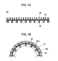
- FIG. 7A is a schematic sectional view showing a structure of the winding direction in producing a negative electrode of a non-aqueous electrolyte secondary battery in accordance with a second exemplary embodiment of the present invention.
- FIG. 7B is a schematic sectional view showing a state when the negative electrode of FIG. 7A is wound.
- FIG. 8A is a schematic sectional view showing a structure of a negative electrode and a positive electrode in the winding direction of a non-aqueous electrolyte secondary battery in accordance with a third exemplary embodiment of the present invention.
- FIG. 8B is a partial sectional view of FIG. 8A for schematically showing a state when the negative electrode and the positive electrode are wound.
- FIG. 1 is a sectional view of a non-aqueous electrolyte secondary battery in accordance with a first exemplary embodiment of the present invention.
- FIG. 2 is a perspective view of an electrode group of the non-aqueous electrolyte secondary battery in accordance with the first exemplary embodiment.
- a cylindrical non-aqueous electrolyte secondary battery (hereinafter referred to as “battery”) has electrode group 4 .
- electrode group 4 is formed by winding, via separator 3 , positive electrode 1 that has positive electrode lead 8 made of aluminum or the like, for example, and reduces lithium ions during discharge, and negative electrode 2 that faces positive electrode 1 and has negative electrode lead 9 made of copper or the like at its one end. Insulating plates 10 and 11 are mounted on the upside and downside of electrode group 4 , the other end of positive electrode lead 8 is welded to sealing plate 6 , the other end of negative electrode lead 9 is welded to the bottom of battery case 5 , and electrode group 4 is inserted into battery case 5 .
- Positive electrode 1 has positive electrode current collector 12 and positive electrode mixture layer 13 including a positive electrode active material.
- Negative electrode 2 has negative electrode current collector 14 , columnar first negative electrode active material 15 disposed on the outer peripheral side thereof in winding, and columnar second negative electrode active material 16 disposed on the inner peripheral side, as described in detail below.
- Positive electrode mixture layer 13 contains, as a positive electrode active material, a lithium-containing complex oxide such as LiCoO 2 , LiNiO 2 , LiMn 2 O 4 , a mixture of them, or a complex compound of them.
- Part of the constituent elements of these lithium-containing compounds may be replaced by a different element.
- the surfaces of these lithium-containing compounds may be treated with metal oxide, lithium oxide, a conductive agent or the like, or may be subjected to hydrophobic treatment.
- Positive electrode mixture layer 13 further includes a conductive agent and a binder.
- the conductive agent include the following materials: graphites such as natural graphite and artificial graphite; carbon blacks such as acetylene black, Ketjen black, channel black, furnace black, lamp black, and thermal black; conductive fibers such as carbon fiber and metal fiber; metal powders of carbon fluoride, aluminum, and the like; conductive whiskers such as zinc oxide and potassium titanate; conductive metal oxides such as titanium oxide; and organic conductive materials such as a phenylene derivative.
- binder examples include polyvinylidene fluoride (PVDF), polytetrafluoroethylene, polyethylene, polypropylene, aramid resin, polyamide, polyimide, polyamideimide, polyacrylonitrile, polyacrylic acid, polymethylacrylate ester, polyethylacrylate ester, polyhexylacrylate ester, polymethacrylic acid, polymethyl methacrylate ester, polyethylmethacrylate ester, polyhexyl methacrylate ester, polyvinyl acetate, polyvinylpyrrolidone, polyether, polyethersulfone, hexafluoropolypropylene, styrene-butadiene rubber, and carboxymethyl cellulose.
- PVDF polyvinylidene fluoride
- aramid resin polyamide
- polyimide polyamideimide
- polyacrylonitrile polyacrylic acid
- polymethylacrylate ester polyethylacrylate ester
- binder examples include copolymers containing at least two selected from tetrafluoroethylene, hexafluoroethylene, hexafluoropropylene, perfluoroalkylvinylether, vinylidene fluoride, chlorotrifluoroethylene, ethylene, propylene, pentafluoropropylene, fluoromethylvinylether, acrylic acid, and hexadiene. Alternatively, two or more of these elements can be mixed.
- positive electrode current collector 12 used in positive electrode 1 examples include aluminum (Al), carbon, and conductive resin. One of these materials may be surface-treated with carbon or the like.
- non-aqueous electrolyte can include electrolytic solution where a solute is dissolved in an organic solvent, or so-called polymer electrolyte that contains the electrolytic solution and is non-fluidized with polymer molecules.
- separator 3 is used between positive electrode 1 and negative electrode 2 and is impregnated with the electrolytic solution.
- Separator 3 is formed of non-woven fabric or micro porous film made of polyethylene, polypropylene, aramid resin, amide-imide, polyphenylene sulfide, or polyimide.
- the inside or surface of separator 3 may contain a heat-resistant filler such as alumina, magnesia, silica, or titania.
- a heat-resistant layer may be disposed that is made of these heat-resistant fillers and the same binder as that used in positive electrode 1 and negative electrode 2 .
- the non-aqueous electrolytic material is selected based on oxidation-reduction potential of each active material.
- the solute preferably used in the non-aqueous electrolyte include the following materials: LiPF 6 ; LiBF 4 ; LiCiO 4 ; LiAlCl 4 ; LiSbF 6 ; LiSCN; LiCF 3 SO 3 ; LiN(CF 3 CO 2 ); LiN(CF 3 SO 2 ) 2 ; LiAsF 6 ; LiB 10 Cl 10 ; lower aliphatic lithium calboxylate; LiF; LiCl; LiBr; LiI; chloroborane lithium; various borates such as bis(1,2-benzendiolate (2-)-O,O′) lithium borate, bis(2,3-naphthalenediolate (2-)-O,O′) lithium borate, bis(2,2′-biphenyldiolate (2-)-O,O′) lithium borate, and bis(5-fluoro-2-olate
- the organic solvent for dissolving the salt can include a solvent generally used in a lithium battery, such as one or a mixture of the following materials: ethylene carbonate (EC); propylene carbonate; butylene carbonate; vinylene carbonate; dimethyl carbonate (DMC); diethyl carbonate; ethyl methyl carbonate (EMC); dipropyl carbonate; methyl formate; methyl acetate; methyl propionate; ethyl propionate; dimethoxymethane; ⁇ -butyrolactone; ⁇ -valerolactone; 1,2-diethoxyethane; 1,2-dimethoxyethane; ethoxymethoxyethane; trimethoxymethane; tetrahydrofuran derivatives such as tetrahydrofuran and 2-methyl-tetrahydrofuran; dimethyl sulfoxide; dioxolane derivatives such as 1,3-dioxolane and 4-methyl-1,3-dioxo
- the solvent may further contain an additive such as vinylene carbonate, cyclohexylbenzene, biphenyl, diphenyl ether, vinylethylene carbonate, divinylethylene carbonate, phenylethylene carbonate, diallyl carbonate, fluoroethylene carbonate, catechol carbonate, vinyl acetate, ethylene sulfite, propanesultone, trifluoropropylene carbonate, dibenzofuran, 2,4-difluoroanisole, o-terphenyl, or m-terphenyl.
- an additive such as vinylene carbonate, cyclohexylbenzene, biphenyl, diphenyl ether, vinylethylene carbonate, divinylethylene carbonate, phenylethylene carbonate, diallyl carbonate, fluoroethylene carbonate, catechol carbonate, vinyl acetate, ethylene sulfite, propanesultone, trifluoropropylene carbonate, dibenzofuran, 2,4-difluoro
- the non-aqueous electrolyte may be used in the form of solid electrolyte by mixing the solute into one or a mixture of the following polymeric materials: polyethylene oxide; polypropylene oxide; polyphosphazene; polyaziridine; polyethylene sulfide; polyvinyl alcohol; polyvinylidene fluoride; and polyhexafluoropropylene.
- the solid electrolyte may be used in a gel form by being mixed into the organic solvent.
- the solid electrolyte may include an inorganic material such as the following material: lithium nitride; lithium halide; lithium oxoate; Li 4 SiO 4 ; Li 4 SiO 4 —LiI—LiOH; Li 3 PO 4 —Li 4 SiO 4 ; Li 2 SiS 3 ; Li 3 PO 4 —Li 2 S—SiS 2 ; or a phosphorus sulfide compound.
- the nonaquaous electrolyte of the gel form it may be disposed instead of the separator between positive electrode 1 and negative electrode 2 .
- the nonaquaous electrolyte of the gel form may be disposed adjacently to separator 3 .
- Examples of negative electrode current collector 14 of negative electrode 2 can include a metal foil made of stainless steel, nickel, copper, or titanium, or a thin film made of carbon or conductive resin.
- the negative electrode current collector may also be surface-treated with carbon, nickel, titanium, or the like.
- First negative electrode active material 15 and second negative electrode active material 16 of negative electrode 2 can be made of material such as silicon (Si) or tin (Sn) that reversely inserts and extracts lithium ions and has a theoretical capacity density exceeding 833 mAh/cm 3 .
- Si silicon
- Sn tin
- Any of a simple substance, alloy, compound, solid solution, and complex active material containing a silicon-containing material or a tin-containing material can exhibit the advantage of the present invention as long as it has above-mentioned features.
- Examples of the silicon-containing material can be made of Si or SiO x (where, 0.05 ⁇ x ⁇ 1.95), or can be made of an alloy, a compound, or a solid solution in which Si is partly replaced with one or more elements selected from the group of B, Mg, Ni, Ti, Mo, Co, Ca, Cr, Cu, Fe, Mn, Nb, Ta, V, W, Zn, C, N, and Sn.
- Examples of the tin-containing material can include Ni 2 Sn 4 , Mg 2 Sn, SnO x (0 ⁇ x ⁇ 2), SnO 2 , SnSiO 3 , and LiSuO.
- the negative electrode active materials may be made of one kind of material or a plurality of kind of materials.
- An example where the negative electrode active materials are made of the plurality of kind of materials is a compound containing Si, oxygen, and nitrogen, or a complex of a plurality of compounds containing Si and oxygen at different component ratios.
- SiO x (0.3 ⁇ x ⁇ 1.3) is preferable because the discharge capacity density is high and the expansion coefficient during charging is smaller than that of pure Si.
- a negative electrode of the non-aqueous electrolyte secondary battery in accordance with the first exemplary embodiment of the present invention is described with reference to FIG. 3A and FIG. 3B .
- FIG. 3A is a schematic sectional view showing a structure of the winding direction in producing the negative electrode of the non-aqueous electrolyte secondary battery in accordance with the first exemplary embodiment.
- FIG. 3B is a schematic sectional view showing a state when the negative electrode of FIG. 3A is wound.
- negative electrode 2 has columnar first negative electrode active materials 15 and second negative electrode active materials 16 in the winding direction on the surface of negative electrode current collector 14 made of copper, for example.
- Active materials 15 and 16 have the same width, different heights, and are made of silicon (Si), for example. In the direction orthogonal to the winding direction, they may be formed continuously to have the same width as that of the negative electrode current collector, or may be formed discretely or zigzag.
- columnar first negative electrode active materials 15 and second negative electrode active materials 16 are formed so as to substantially equalize the porosity on the outer peripheral side of negative electrode 2 to that on the inner peripheral side thereof in winding.
- the porosity in space 15 a defined by the interval between first negative electrode active materials 15 and the height of them is substantially equalized to that in space 16 a defined by the interval between second negative electrode active materials 16 and the height of them.
- the capacity density of the first negative electrode active materials is substantially equalized to that of the second negative electrode active materials. Therefore, the height of first negative electrode active materials is made lower than that of second negative electrode active materials in the present embodiment.
- the porosity on the inner peripheral side of the negative electrode can be substantially equalized to that on the outer peripheral side thereof.
- a cylindrical battery is produced where the core diameter is 3 mm and the diameter of the electrode group is about 18 mm.
- the substantial equalization of the porosity on the outer peripheral side of negative electrode 2 to that on the inner peripheral side thereof indicates the following point.
- a usual electrode plate where the amount and density of the active material on the front side are equal to those on the back side is wound, density is reduced on the outer peripheral side in winding and compression stress is applied on the inner peripheral side. Therefore, the porosity on the inner peripheral side differs from that on the outer peripheral side.
- An electrode plate must be previously produced in consideration of the difference between the porosities.
- the electrode group is formed using the electrode plate where the porosity on the inner peripheral side is set larger than that on the outer peripheral side.
- the active material amounts must be varied in response to the winding curvature while the shapes or the like of the first and second negative electrode active materials are varied.
- this method is not practical in consideration of the productivity.
- the following structure is appropriately employed, so that the advantage of the present invention can be obtained without reducing the productivity.
- the porosities on the inner peripheral side and outer peripheral side of the negative electrode in winding are described hereinafter.
- the thickness of the current collector is to, the thickness of the first negative electrode active material on the outer peripheral side is t 1 , the solid percent per unit volume of the first negative electrode active material is N 1 , the thickness of the second negative electrode active material on the inner peripheral side is t 2 , and the solid percent per unit volume of the second negative electrode active material is N 2 .
- the solid percent means the volume ratio of the negative electrode active material to the electrode plate volume.
- the solid percent means the volume ratio of the negative electrode mixture to the electrode plate volume.
- each negative electrode active material is sometimes represented as the height in the case of employing the columnar negative electrode active material of the present embodiment of the present invention.
- the thickness of the current collector is 10 ⁇ m
- the thickness (height) of both the columnar first and second negative electrode active materials is 30 ⁇ m
- the solid percent per unit volume of the active materials is 70%
- the porosities on the outer peripheral side and inner peripheral side in the winding innermost periphery are 30.7% and 29.3%, respectively.
- the difference between the porosities is about 1.4%.
- the difference between the porosities in the winding outermost periphery is about 0.2%.
- the thickness (height) and width of the columnar first negative electrode active materials are 15 ⁇ m and 10 ⁇ m
- the thickness (height) and width of the columnar second negative electrode active materials are 30 ⁇ m and 10 ⁇ m
- the solid percent per unit volume is 70%
- the porosities on the outer peripheral side and inner peripheral side in the winding innermost periphery are 30.3% and 29.3%, respectively.
- the difference between the porosities is about 1%.
- the difference between the porosities in the winding outermost periphery is about 0.2%.
- the substantial equalization of the porosity on the inner peripheral side of the negative electrode to that on the outer peripheral side thereof indicates that the difference between the porosities is reduced to 1.1% or lower, for example, in the present invention, differently from the porosities when conventional uniform negative electrode active material is used. Therefore, porosity v 1 on the outer peripheral side is equal to porosity v 2 on the inner peripheral side at a specific winding radius, but porosity v 1 is not always equal to porosity v 2 in the whole region of the wound electrode group.
- the porosities can be designed arbitrarily using relational expressions Eq. 1 and Eq. 2 in response to the desired characteristic of the secondary battery.
- the densities of the negative electrode active materials on the inner peripheral side and outer peripheral side of the negative electrode can be uniformed regardless of the winding curvature by optimizing the shapes or the like of the columnar negative electrode active materials.
- the porosity difference between the first negative electrode active material and second negative electrode active material formed on the outer peripheral side and inner peripheral side of the negative electrode in winding can be substantially nulled or reduced.
- the amounts of non-aqueous electrolyte coming into contact with respective negative electrode active materials can be substantially equalized. Since the capacity density of the first negative electrode active material is substantially equal to that of the second negative electrode active material, the amount of inserted lithium ions is substantially equal to that of extracted lithium ions. As a result, the strain due to the expansion and contraction of respective negative electrode active materials on the outer and inner peripheral sides of the negative electrode becomes uniform, and a negative electrode that does not cause peeling or the like is obtained.
- the negative electrode where the porosity and capacity density are substantially uniformed in winding is employed, so that a non-aqueous electrolyte secondary battery can be achieved that has a uniform non-aqueous electrolyte amount on the inner and outer peripheral sides of the negative electrode, can efficiently insert and extract lithium ions, and has a large capacity.
- the solid percent per unit volume of the columnar first and second negative electrode active materials is made constant, and the thickness (height) is varied.
- the thickness (height) at the position moving from the winding center to the outer periphery may be varied in response to the curvature, for example.
- the porosity on the outer peripheral side of the negative electrode can be designed to be substantially equal to that on the inner peripheral side thereof in the whole circumference of the electrode group, so that the characteristic of the secondary battery is improved.
- a manufacturing method of a negative electrode of a non-aqueous electrolyte secondary battery in accordance with the present exemplary embodiment of the present invention is described in detail with reference to FIG. 4A through FIG. 4E .
- FIG. 4A through FIG. 4E are sectional views illustrating a manufacturing step of the negative electrode of the non-aqueous electrolyte secondary battery in accordance with the first exemplary embodiment.
- 10 ⁇ m-thick negative electrode current collector 14 made of copper is prepared as shown in FIG. 4A .
- first deposition mask 20 defining a columnar first negative electrode active material is disposed on one surface of negative electrode current collector 14 , for example, on the surface positioned on the outer peripheral side in winding.
- First deposition mask 20 has predetermined openings at predetermined intervals in the winding direction.
- negative electrode current collector 14 having first deposition mask 20 is disposed inside vacuum deposition apparatus. Silicon (Si) is deposited in an oxygen (O 2 ) atmosphere, for example.
- first negative electrode active materials 15 made of SiO x (0 ⁇ x ⁇ 0.3), for example, are formed in a predetermined columnar shape on one surface of negative electrode current collector 14 .
- second deposition mask 22 defining a columnar second negative electrode active material is disposed on the other surface of negative electrode current collector 14 , for example, on the surface positioned on the inner peripheral side in winding.
- Negative electrode current collector 14 having second deposition mask 22 is disposed inside vacuum deposition apparatus, for example. Silicon (Si) is deposited in an oxygen (O 2 ) atmosphere, for example.
- second negative electrode active materials 16 made of SiO x (0 ⁇ x ⁇ 0.3), for example are formed in a columnar shape at least higher than the first negative electrode active materials on the other surface of negative electrode current collector 14 .
- This structure can be achieved by adjusting the deposition energy and deposition time. The difference of height is determined so that the porosity between the first negative electrode active materials is substantially equal to or smaller than that between the second negative electrode active materials when the negative electrode is wound.
- negative electrode 2 having the first negative electrode active materials and second negative electrode active materials having different heights on both surfaces of the negative electrode current collector is produced.
- the intervals and widths are set so that the capacity density of the formed first negative electrode active materials is substantially equal to that of the formed second negative electrode active materials in winding.
- each columnar negative electrode active material As a method of forming each columnar negative electrode active material, a usually used vapor phase method such as an ion plating method, electron beam deposition method, or sputtering method is employed in addition to the above-mentioned method.
- a usually used vapor phase method such as an ion plating method, electron beam deposition method, or sputtering method is employed in addition to the above-mentioned method.
- each negative electrode active material is formed using the deposition mask.
- each columnar negative electrode active material may be formed by obliquely performing deposition on a negative electrode current collector having an irregular surface.
- each columnar negative electrode active material may be formed by obliquely performing deposition on a negative electrode current collector having a wavy surface.
- each first negative electrode active materials and each second negative electrode active materials may be formed in different oblique directions.
- oblique columnar negative electrode active materials are grown and formed while the negative electrode active materials are partially shielded by the projecting parts or the like during oblique deposition. Therefore, the deposition mask is not required, and a negative electrode with a simple structure can be produced with high productivity.
- each negative electrode active material is formed orthogonally to the negative electrode current collector.
- the present invention is not limited to this.
- oblique columnar negative electrode active materials shown in FIG. 5A , FIG. 5B , FIG. 6A , and FIG. 6B may be formed by disposing a deposition mask in a separated state from the negative electrode current collector and evaporating silicon or the like obliquely.
- the negative electrode active materials are formed to have a quadrangular sectional shape.
- the sectional shape may be an arbitrary shape such as trapezoid or inverted trapezoid.
- a negative electrode of a non-aqueous electrolyte secondary battery in accordance with a second exemplary embodiment of the present invention is described hereinafter with reference to FIG. 7A and FIG. 7B .
- Each structure and material of the secondary battery except negative electrode 32 are similar to those of the first exemplary embodiment, and the descriptions of them are omitted.
- FIG. 7A is a schematic sectional view showing a structure of the winding direction in producing the negative electrode of the non-aqueous electrolyte secondary battery in accordance with the second exemplary embodiment.
- FIG. 7B is a schematic sectional view showing the state when the negative electrode of FIG. 7A is wound.
- Each first negative electrode active material and each second negative electrode active material of the second exemplary embodiment are different from those of the first exemplary embodiment in that the heights of the negative electrode active materials are the same in the winding direction and the width of the winding direction of the second negative electrode active material is made greater.
- negative electrode 32 has columnar first negative electrode active materials 35 and columnar second negative electrode active materials 36 on the surfaces of negative electrode current collector 34 made of copper, for example.
- Active materials 35 and 36 have the same height and different width in the winding direction and are made of silicon (Si) or the like. In the direction orthogonal to the winding direction, the active materials may be continuously formed to have the same width as that of the negative electrode current collector, or may be formed discretely or zigzag.
- columnar first negative electrode active materials 35 and columnar second negative electrode active materials 36 are formed so as to substantially equalize the porosity on the outer peripheral side of negative electrode 32 to that on the inner peripheral side thereof in winding.
- the porosity in space 35 a defined by the interval between first negative electrode active materials 35 and the height of them is substantially equalized to that in space 36 a defined by the interval between second negative electrode active materials 36 and the height of them.
- the capacity density of the first negative electrode active materials is substantially equalized to that of the second negative electrode active materials. Therefore, in the present embodiment, the width of the second negative electrode active materials is made greater than that of first negative electrode active materials.
- the substantial equalization of the porosities has the same meaning as that of the first exemplary embodiment.
- the thickness (height) and width of the columnar first negative electrode active materials are 20 ⁇ m and 10 ⁇ m
- the thickness (height) and width of the columnar second negative electrode active materials are 20 ⁇ m and 5 ⁇ m
- the solid percent per unit volume is 70%
- the porosities on the outer peripheral surface and inner peripheral surface in the winding innermost periphery are 30.5% and 29.5%, respectively.
- the difference between the porosities is about 1%.
- the difference between the porosities in the winding outermost periphery is about 0.2%.
- the porosity difference between each first negative electrode active material and each second negative electrode active material formed on the outer peripheral side and inner peripheral side of the negative electrode in winding can be substantially nulled or reduced, and the amounts of non-aqueous electrolyte coming into contact with respective negative electrode active materials can be substantially equalized. Since the density of the first negative electrode active material is substantially equal to that of the second negative electrode active material, the amount of inserted lithium ions is substantially equal to that of extracted lithium ions. As a result, the strain due to the expansion and contraction of respective negative electrode active materials on the outer and inner peripheral sides of the negative electrode becomes uniform, and a negative electrode that does not cause peeling or the like is obtained.
- the negative electrode where the porosity and capacity density are substantially uniformed in winding is employed, so that a non-aqueous electrolyte secondary battery can be achieved that has uniform non-aqueous electrolyte amount on the inner and outer peripheral sides of the negative electrode, can efficiently insert and extract lithium ions, and has a large capacity.
- the height of the second negative electrode active material can be reduced, so that the thickness of the negative electrode can be reduced. Therefore, the number of winding turns is increased, the area of the negative electrode facing the positive electrode is enlarged, and hence a secondary battery having higher capacity can be achieved.
- a non-aqueous electrolyte secondary battery in accordance with a third exemplary embodiment of the present invention is described hereinafter with reference to FIG. 8A and FIG. 8B .
- Each structure and material of the secondary battery except negative electrode 62 and positive electrode 51 are similar to those of the first exemplary embodiment, and the descriptions of them are omitted.
- FIG. 8A is a schematic sectional view showing a structure of the negative electrode and the positive electrode in the winding direction of the non-aqueous electrolyte secondary battery in accordance with the third exemplary embodiment of the present invention.
- FIG. 8B is a partial sectional view of FIG. 8A for schematically showing a state when the negative electrode and the positive electrode are wound. In FIG. 8A and FIG. 8B , for sake of simplicity, the separator is not drawn.
- each columnar first negative electrode active material and each columnar second negative electrode active material have the same height and width and a different forming interval in the winding direction, so that the porosities in winding are substantially equalized. Therefore, in the negative electrode, the capacity densities of the negative electrode active materials on the inner and outer peripheral sides in winding are different from each other. Therefore, the capacity density of the positive electrode active material in the positive electrode mixture layer forming the positive electrode is substantially equalized to that of the first negative electrode active materials and second negative electrode active materials of the negative electrode facing it. Specifically, the thicknesses of the positive electrode mixture layers on the inner and outer peripheral sides of the positive electrode are different from each other, and the capacity densities thereof are also different from each other.
- negative electrode 62 has columnar first negative electrode active materials 65 and columnar second negative electrode active materials 66 on the surfaces of negative electrode current collector 64 made of copper, for example.
- Active materials 65 and 66 have the same height and the same width, are formed at different intervals in the winding direction, and are made of silicon (Si) or the like.
- the negative electrode active materials may be continuously formed to have the same width as that of the negative electrode current collector, or may be formed discretely or zigzag.
- columnar first negative electrode active materials 65 and columnar second negative electrode active materials 66 are formed so as to substantially equalize the porosity on the outer peripheral side of negative electrode 62 to that on the inner peripheral side thereof in winding.
- the porosity in space 65 a defined by the interval between first negative electrode active materials 65 and the height of them is substantially equalized to that in space 66 a defined by the interval between second negative electrode active materials 66 and the height of them.
- the capacity density of the first negative electrode active materials cannot be equalized to that of the second negative electrode active materials.
- the capacity density of first negative electrode active materials 65 is substantially equalized to that of the positive electrode active material in positive electrode mixture layer 53 of positive electrode 51 facing first negative electrode active materials 65 .
- the capacity density of second negative electrode active materials 66 is substantially equalized to that of the positive electrode active material in positive electrode mixture layer 54 of positive electrode 51 facing second negative electrode active materials 66 .
- the substantial equalization is by varying the thicknesses of positive electrode mixture layers 53 and 54 formed on both surfaces of positive electrode current collector 52 of positive electrode 51 .
- the thickness and width of the columnar first negative electrode active materials are 20 ⁇ m and 10 ⁇ m
- the thickness and width of the columnar second negative electrode active materials are 20 ⁇ m and 10 ⁇ m
- the solid percent per unit volume of the first negative electrode active materials is 70%
- the solid percent per unit volume of the second negative electrode active materials is 69%
- both the porosities on the outer peripheral surface and inner peripheral surface in the winding innermost periphery are 30.5%.
- the difference between the porosities in the winding outermost periphery is about 0.8%.
- the thickness of the positive electrode mixture layer facing the first negative electrode active materials is 60 ⁇ m, and the thickness of the positive electrode mixture layer facing the second negative electrode active materials is 58 ⁇ m.
- the positive electrode mixture layers having different thickness lying on the inner and outer peripheries of the positive electrode are produced by the following method.
- LiCoO 2 powder as the positive electrode active materials is mixed with 4 parts by weight of acetylene black as a conductive agent, for example.
- NMP N-methyl-2-pyrrolidone
- PVDF polyvinylidene fluoride
- the prepared paste for the positive electrode mixture as much as the amount equivalent to the capacity density of the first negative electrode active materials is applied to the positive electrode current collector (thickness: 15 ⁇ m) made of aluminum (Al) foil using a doctor blade method, and is dried. Further, the amount equivalent to the capacity density of the second negative electrode active materials is applied to the rear surface, and is dried.
- the produced matter is rolled so that the thickness of the positive electrode mixture layer facing the first negative electrode active materials is 60 ⁇ m, the thickness of the positive electrode mixture layer facing the second negative electrode active materials is 58 ⁇ m, and the whole thickness is 129 ⁇ m, for example.
- the rolled matter is cut into a predetermined size, thereby producing a positive electrode.
- each first negative electrode active material and each second negative electrode active material formed on the outer peripheral side and inner peripheral side of the negative electrode in winding can be substantially nulled or reduced, and the amounts of non-aqueous electrolyte coming into contact with respective negative electrode active materials can be substantially equalized. Since the positive electrode mixture layers that face the first negative electrode active material and second negative electrode active material and have capacity densities substantially equal to those of them, respectively, the amount of lithium ions inserted between the facing positive electrode and negative electrode becomes equal to that of lithium ions extracted between them. As a result, the lithium ions can be effectively used.
- negative electrode active materials of high expansion and contraction can be used, and a non-aqueous electrolyte secondary battery of high capacity capable of efficiently inserting and extracting lithium ions is produced.
- the solid percent of the first negative electrode active material or second negative electrode active material is constant in the whole circumference of the negative electrode.
- the solid percent may be varied in response to the curvature in winding.
- the productivity reduces, but the porosity on the outer peripheral side of the negative electrode can be substantially equalized to that on the inner peripheral side in the whole circumference in winding.
- the strain during expansion and contraction on the outer peripheral side and inner peripheral side of the negative electrode can be uniformed, so that the secondary battery of high reliability is produced.
- a negative electrode in accordance with the first exemplary embodiment and a secondary battery including the negative electrode are produced.
- a negative electrode capable of inserting and extracting lithium ions is produced in the following method.
- a negative electrode active material capable of inserting and extracting lithium ions silicon oxide (SiO x ) produced by vacuum-depositing silicon (Si) in an oxygen atmosphere is used.
- columnar first negative electrode active materials width: 10 ⁇ m, thickness: 15 ⁇ m, solid percent: 70%
- columnar second negative electrode active materials width: 10 ⁇ m, thickness: 30 ⁇ m, solid percent: 70%
- the first negative electrode active materials are formed on the deposition condition that the oxygen amount is 30 sccm, the deposition rate is 2 ⁇ m/min., and the electron gun output is 7 kW.
- the second negative electrode active materials are formed on the deposition condition that the oxygen amount is 30 sccm, the deposition rate is 1 ⁇ m/min, and the electron gun output is 7 kW.
- an exposed part of 30 mm is disposed on the inner peripheral side of the negative electrode and in Cu foil that does not face the positive electrode, and a negative electrode lead made of Cu is welded to the exposed part.
- a positive electrode having a positive electrode active material capable of inserting and extracting lithium ions is produced in the following method.
- NMP N-methyl-2-pyrrolidone
- PVDF polyvinylidene fluoride
- the prepared paste for the positive electrode mixture is applied to the positive electrode current collector (thickness: 15 ⁇ m) made of aluminum (Al) foil using a doctor blade method, is rolled so that the density of the positive electrode mixture layer is 3.5 g/cc and the thickness is 129 ⁇ m, and is sufficiently dried at 85° C.
- the dried matter is cut into a width of 57 mm and a length of 600 mm, thereby producing a positive electrode.
- An exposed part of 30 mm is disposed on the inner peripheral side of the positive electrode and in Al foil that does not face the negative electrode, and a positive electrode lead made of Al is welded to the exposed part.
- the produced negative electrode and positive electrode are wound via a 20 ⁇ m thick separator made of polypropylene, thereby forming an electrode group.
- the obtained electrode group is inserted into a battery case (material: iron/Ni-plated, diameter: 18 mm, height: 65 mm) for cylindrical battery having only one opening side, an insulating plate is disposed between the battery case and the electrode group, the negative lead is welded to the battery case, and then the positive lead is welded to a sealing plate, thereby producing a battery.
- This battery is heated to 60° C. in vacuum and dried, then 5.8 g of electrolyte that is produced by dissolving 1.2 mol/dm 3 of LiPF 6 in a non-aqueous solvent containing ethylene carbonate (EC), dimethyl carbonate (DMC), and ethyl methyl carbonate (EMC) at volume ratio of 2:3:3 is injected, and the sealing plate is sealed by crimping by the battery case, thereby producing a non-aqueous electrolyte secondary battery.
- This non-aqueous electrolyte secondary battery is called sample 1.
- a negative electrode in accordance with the second exemplary embodiment and a secondary battery including the negative electrode are produced.
- the non-aqueous electrolyte secondary battery is produced in a method similar to that of embodied example 1 except that columnar first negative electrode active materials (width: 10 ⁇ m, thickness: 20 ⁇ m, solid percent: 70%) and columnar second negative electrode active materials (width: 5 ⁇ m, thickness: 20 ⁇ m, solid percent: 70%) are formed on both surfaces of negative electrode current collector (thickness: 10 ⁇ m) made of copper foil.
- This non-aqueous electrolyte secondary battery is called sample 2.
- a negative electrode and positive electrode in accordance with the third exemplary embodiment and a secondary battery including them are produced.
- the secondary battery is produced in a method similar to that of embodied example 1 except that columnar first negative electrode active materials (width: 10 ⁇ m, thickness: 20 ⁇ m, solid percent: 70%) and columnar second negative electrode active materials (width: 10 ⁇ m, thickness: 20 ⁇ m, solid percent: 69%) are formed on both surfaces of negative electrode current collector (thickness: 10 ⁇ m) made of copper foil.
- an electrode plate is produced where the thickness of the positive electrode mixture layer facing the first negative electrode active materials is 60 ⁇ m, the thickness of the positive electrode mixture layer facing the second negative electrode active materials is 58 ⁇ m, and the whole thickness is 129 ⁇ m.
- the electrode plate is cut into a width of 57 mm and a length of 600 mm to form the positive electrode.
- An exposed part of 30 mm is disposed on the inner peripheral side of the positive electrode and in Al foil that does not face the negative electrode, and a positive lead made of Al is welded to the exposed part.
- a non-aqueous electrolyte secondary battery is produced in the method similar to that of embodied example 1.
- This non-aqueous electrolyte secondary battery is called sample 3.
- a non-aqueous electrolyte secondary battery is produced in a method similar to that of embodied example 1 except that the negative electrode is formed by disposing columnar negative electrode active materials having a solid percent of 70%, the same height, the same width, and the same interval on both sides of the negative electrode current collector.
- This secondary battery is called sample C1.
- Each produced non-aqueous electrolyte secondary battery is evaluated as follows.
- Each non-aqueous electrolyte secondary battery is charged and discharged at an ambient temperature of 25° C. First, charge is performed at a constant current of 0.7 C hour rate to design capacity (2800 mAh) until the battery voltage becomes 4.2 V, and constant voltage charge of attenuating the current to a value of 0.05 C hour rate at a constant voltage of 4.2 V is performed. After that, a rest of 30 minutes is taken.
- discharge is performed at a constant current of 0.2 C hour rate until the battery voltage decreases to 2.5 V.
- the discharge capacity at this time is set as the battery capacity (or initial capacity).
- Each produced non-aqueous electrolyte secondary battery is repeatedly charged and discharged at an ambient temperature of 25° C. on the following condition.
- charge is performed at a constant current of 0.5 C hour rate to design capacity (2800 mAh) until the battery voltage becomes 4.2 V, and charge is performed at a constant voltage of 4.2 V until the charge current decreases to a value of 0.05 C hour rate. After that, a rest of 30 minutes is taken.
- the above-mentioned charge-discharge cycle is set to be one cycle, and repeated 100 times.
- the ratio of the discharge capacity of 100th cycle to that of first cycle is defined as the capacity retaining ratio (%). In other words, as the capacity retaining ratio approaches 100, the charge-discharge cycle characteristic becomes high.
- the buckling situation of the electrode group is recognized in a full charge state by computed-tomography (CT)-scanning the battery having undergone the charge-discharge cycle.
- CT computed-tomography
- the group diameter of the electrode group is measured by processing the CT scan image. At this time, first, a secondary battery where the group diameter of the electrode group is 17.50 mm is selected and evaluated.
- the porosity difference in the outermost periphery of the electrode group hardly affects the cycle characteristic or the like.
- the initial capacity is small because the amount of the negative electrode active material is relatively small.
- winding-type cylindrical non-aqueous electrolyte secondary battery is described.
- the shape of a battery of the present invention is not limited to the cylindrical shape.
- a flat battery, a winding-type square battery, a coin-shaped battery of laminated structure, and a laminated battery may be used.
- the present invention is useful for achieving, using a negative electrode active material of high expansion and contraction, a non-aqueous electrolyte secondary battery of high capacity and reliability that is expected to be greatly demanded in the future.
Landscapes
- Chemical & Material Sciences (AREA)
- Engineering & Computer Science (AREA)
- Materials Engineering (AREA)
- Chemical Kinetics & Catalysis (AREA)
- Electrochemistry (AREA)
- General Chemical & Material Sciences (AREA)
- Manufacturing & Machinery (AREA)
- Secondary Cells (AREA)
- Battery Electrode And Active Subsutance (AREA)
Abstract
Description
- [Patent document 1] Japanese Patent Unexamined Publication No. H06-76819
- [Patent document 2] Japanese Patent Unexamined Publication No. 2002-313319
-
- a negative electrode having columnar first negative electrode active materials that are formed on the outer peripheral surface of a negative electrode current collector in the winding direction so as to reversibly insert and extract lithium ions, and having columnar second negative electrode active materials that are formed on the inner peripheral surface;
- a positive electrode having positive electrode mixture layers containing a positive electrode active material capable of reversibly inserting and extracting lithium ions, on both surfaces of a positive electrode current collector; and
- a separator between the positive electrode and negative electrode in a state facing to them.
The difference between the porosity generated between the first negative electrode active materials in the negative electrode and the porosity generated between the second negative electrode active materials in winding is set within 1.1%.
- 1, 51 positive electrode
- 2, 32, 62 negative electrode
- 3 separator
- 4 electrode group
- 5 battery case
- 6 sealing plate
- 7 gasket
- 8 positive electrode lead
- 9 negative electrode lead
- 10, 11 insulating plates
- 12, 52 positive electrode current collector
- 13, 53, 54 positive electrode mixture layer
- 14, 34, 64 negative electrode current collector
- 15, 35, 65 first negative electrode active material
- 15 a, 16 a, 35 a, 36 a, 65 a, 66 a space
- 16, 36, 66 second negative electrode active material
- 20 first deposition mask
- 22 second deposition mask
v 1=2r(1−N 1)/{2(r+t 0)+t 1} Eq. 1,
and
v 2=2r(1−N 2)/(2r−t 2) Eq. 2.
| TABLE 1 | |||
| Specifications | Evaluation results | ||
| Porosity | Porosity | After 100 cycles |
| difference | difference | Initial | Capacity | Group | ||
| in innermost | in outermost | capacity | retaining | diameter | ||
| periphery [%] | periphery [%] | [mAh] | ratio [%] | [mm] | ||
| |
1.1 | 0.2 | 2803 | 87 | 17.61 |
| |
1 | 0.2 | 2785 | 89 | 17.54 |
| |
0 | 0.8 | 2721 | 89 | 17.52 |
| Sample C1 | 1.4 | 0.2 | 2787 | 81 | 17.68 |
Claims (15)
Applications Claiming Priority (3)
| Application Number | Priority Date | Filing Date | Title |
|---|---|---|---|
| JP2006242450 | 2006-09-07 | ||
| JP2006242450 | 2006-09-07 | ||
| PCT/JP2007/066969 WO2008029719A1 (en) | 2006-09-07 | 2007-08-31 | Nonaqueous electrolytic secondary cell |
Publications (2)
| Publication Number | Publication Date |
|---|---|
| US20090317721A1 US20090317721A1 (en) | 2009-12-24 |
| US8313862B2 true US8313862B2 (en) | 2012-11-20 |
Family
ID=39157150
Family Applications (1)
| Application Number | Title | Priority Date | Filing Date |
|---|---|---|---|
| US12/064,307 Expired - Fee Related US8313862B2 (en) | 2006-09-07 | 2007-08-31 | Non-aqueous battery with columnar active material |
Country Status (4)
| Country | Link |
|---|---|
| US (1) | US8313862B2 (en) |
| JP (1) | JP4831075B2 (en) |
| CN (1) | CN101346850B (en) |
| WO (1) | WO2008029719A1 (en) |
Families Citing this family (40)
| Publication number | Priority date | Publication date | Assignee | Title |
|---|---|---|---|---|
| WO2009131700A2 (en) | 2008-04-25 | 2009-10-29 | Envia Systems, Inc. | High energy lithium ion batteries with particular negative electrode compositions |
| US20090297949A1 (en) * | 2008-05-29 | 2009-12-03 | Berkowitz Fred J | Lithium Primary Cells |
| US9012073B2 (en) * | 2008-11-11 | 2015-04-21 | Envia Systems, Inc. | Composite compositions, negative electrodes with composite compositions and corresponding batteries |
| JP5446612B2 (en) * | 2009-08-28 | 2014-03-19 | Tdk株式会社 | Lithium ion secondary battery |
| US20110200886A1 (en) * | 2009-09-29 | 2011-08-18 | Masaki Deguchi | Non-aqueous electrolyte and non-aqueous electrolyte secondary battery using the same |
| US9190694B2 (en) * | 2009-11-03 | 2015-11-17 | Envia Systems, Inc. | High capacity anode materials for lithium ion batteries |
| JP5472759B2 (en) * | 2009-12-17 | 2014-04-16 | トヨタ自動車株式会社 | Lithium secondary battery |
| JP2012146480A (en) * | 2011-01-12 | 2012-08-02 | Dainippon Screen Mfg Co Ltd | Method for producing electrode, battery electrode and battery |
| US9601228B2 (en) * | 2011-05-16 | 2017-03-21 | Envia Systems, Inc. | Silicon oxide based high capacity anode materials for lithium ion batteries |
| JP5660625B2 (en) * | 2011-06-30 | 2015-01-28 | Fdkトワイセル株式会社 | Manufacturing method of negative electrode plate |
| US9257717B2 (en) * | 2011-07-22 | 2016-02-09 | Panasonic Intellectual Property Management Co., Ltd. | Nonaqueous electrolyte secondary battery |
| JP5828342B2 (en) * | 2011-09-01 | 2015-12-02 | トヨタ自動車株式会社 | Nonaqueous electrolyte secondary battery |
| JP5542780B2 (en) | 2011-11-01 | 2014-07-09 | 信越化学工業株式会社 | Negative electrode active material for non-aqueous electrolyte secondary battery and method for producing the same |
| US9139441B2 (en) | 2012-01-19 | 2015-09-22 | Envia Systems, Inc. | Porous silicon based anode material formed using metal reduction |
| US9780358B2 (en) | 2012-05-04 | 2017-10-03 | Zenlabs Energy, Inc. | Battery designs with high capacity anode materials and cathode materials |
| US10553871B2 (en) | 2012-05-04 | 2020-02-04 | Zenlabs Energy, Inc. | Battery cell engineering and design to reach high energy |
| WO2014073113A1 (en) * | 2012-11-12 | 2014-05-15 | トヨタ自動車株式会社 | Nonaqueous electrolyte secondary battery |
| US10020491B2 (en) | 2013-04-16 | 2018-07-10 | Zenlabs Energy, Inc. | Silicon-based active materials for lithium ion batteries and synthesis with solution processing |
| US10886526B2 (en) | 2013-06-13 | 2021-01-05 | Zenlabs Energy, Inc. | Silicon-silicon oxide-carbon composites for lithium battery electrodes and methods for forming the composites |
| WO2015024004A1 (en) | 2013-08-16 | 2015-02-19 | Envia Systems, Inc. | Lithium ion batteries with high capacity anode active material and good cycling for consumer electronics |
| CN103606705A (en) * | 2013-11-27 | 2014-02-26 | 北京国能电池科技有限公司 | Lithium ion battery and preparation method thereof |
| WO2015133066A1 (en) * | 2014-03-05 | 2015-09-11 | パナソニックIpマネジメント株式会社 | Thin battery and battery-mounted device |
| JP2019075306A (en) * | 2017-10-17 | 2019-05-16 | トヨタ自動車株式会社 | Charger of lithium ion secondary battery, and method for charging/discharging lithium ion secondary battery |
| US11094925B2 (en) | 2017-12-22 | 2021-08-17 | Zenlabs Energy, Inc. | Electrodes with silicon oxide active materials for lithium ion cells achieving high capacity, high energy density and long cycle life performance |
| JP7113227B2 (en) * | 2018-03-09 | 2022-08-05 | パナソニックIpマネジメント株式会社 | lithium secondary battery |
| JP7113226B2 (en) * | 2018-03-09 | 2022-08-05 | パナソニックIpマネジメント株式会社 | lithium secondary battery |
| EP3576196A1 (en) * | 2018-05-31 | 2019-12-04 | Panasonic Intellectual Property Management Co., Ltd. | Lithium secondary battery |
| EP3576183B1 (en) * | 2018-05-31 | 2023-05-31 | Panasonic Intellectual Property Management Co., Ltd. | Lithium secondary battery |
| EP3576186B1 (en) * | 2018-05-31 | 2023-05-31 | Panasonic Intellectual Property Management Co., Ltd. | Lithium secondary battery |
| EP3576184B1 (en) * | 2018-05-31 | 2023-05-31 | Panasonic Intellectual Property Management Co., Ltd. | Lithium secondary battery |
| EP3576185B1 (en) * | 2018-05-31 | 2023-02-01 | Panasonic Intellectual Property Management Co., Ltd. | Lithium secondary battery |
| EP3576191B1 (en) * | 2018-05-31 | 2022-10-05 | Panasonic Intellectual Property Management Co., Ltd. | Lithium secondary battery |
| JP7096184B2 (en) * | 2019-03-12 | 2022-07-05 | トヨタ自動車株式会社 | Lithium-ion secondary battery and its manufacturing method |
| US11973178B2 (en) | 2019-06-26 | 2024-04-30 | Ionblox, Inc. | Lithium ion cells with high performance electrolyte and silicon oxide active materials achieving very long cycle life performance |
| US12040478B2 (en) * | 2019-11-05 | 2024-07-16 | Enevate Corporation | Anisotropic expansion of silicon-dominant anodes |
| US12355079B2 (en) | 2020-07-02 | 2025-07-08 | Ionblox, Inc. | Lithium ion cells with silicon based active materials and negative electrodes with water-based binders having good adhesion and cohesion |
| JP7657060B2 (en) * | 2021-02-01 | 2025-04-04 | 本田技研工業株式会社 | Negative electrode for non-aqueous electrolyte secondary battery and non-aqueous electrolyte secondary battery including the same |
| US20220285723A1 (en) * | 2021-03-05 | 2022-09-08 | Enevate Corporation | Method And System For Safety Of Silicon Dominant Anodes |
| CN115911270B (en) * | 2022-11-29 | 2025-12-16 | 楚能新能源股份有限公司 | Quick-charging type negative electrode plate, battery cell containing same and battery |
| CN116805729B (en) * | 2023-08-22 | 2024-02-27 | 苏州清陶新能源科技有限公司 | A method for preparing a composite pole piece, a composite pole piece and a lithium battery |
Citations (16)
| Publication number | Priority date | Publication date | Assignee | Title |
|---|---|---|---|---|
| JPH0412471A (en) | 1990-04-28 | 1992-01-17 | Sony Corp | Secondary battery |
| JPH0676819A (en) | 1992-08-31 | 1994-03-18 | Sanyo Electric Co Ltd | Electrode plate for cylindrical battery and manufacture thereof |
| JPH06290774A (en) | 1993-03-30 | 1994-10-18 | Sanyo Electric Co Ltd | Nonaqueous electrolyte secondary battery |
| JPH08130035A (en) | 1994-09-07 | 1996-05-21 | Fuji Photo Film Co Ltd | Nonaqueous secondary battery |
| US5683834A (en) * | 1994-09-07 | 1997-11-04 | Fuji Photo Film Co., Ltd. | Nonaqueous secondary battery |
| JPH1064522A (en) | 1996-08-12 | 1998-03-06 | Toshiba Battery Co Ltd | Manufacture of sheet-like electrode plate and nonaqueous electrolyte battery |
| US20010012588A1 (en) | 1996-06-19 | 2001-08-09 | Toshiba Battery Co., Ltd. | Nonaqueous electrolyte battery, electrode plate for nonaqueous electrolyte battery, and method for manufacturing electrode plate for nonaqueous electrolyte battery, |
| JP2002313319A (en) | 2001-04-09 | 2002-10-25 | Sanyo Electric Co Ltd | Electrode for lithium secondary battery and lithium secondary battery |
| JP2002313345A (en) | 2001-04-13 | 2002-10-25 | Japan Storage Battery Co Ltd | Non-aqueous electrolyte secondary battery |
| JP2004031217A (en) | 2002-06-27 | 2004-01-29 | Sony Corp | battery |
| JP2004296103A (en) | 2003-03-25 | 2004-10-21 | Sanyo Electric Co Ltd | Non-aqueous electrolyte for secondary battery and non-aqueous electrolyte secondary battery |
| JP2004319469A (en) | 2003-04-02 | 2004-11-11 | Matsushita Electric Ind Co Ltd | Negative electrode active material and non-aqueous electrolyte secondary battery using the same |
| US20050058904A1 (en) * | 2003-08-21 | 2005-03-17 | Gentaro Kano | Battery |
| US20050074671A1 (en) * | 2002-09-30 | 2005-04-07 | Hiromu Sugiyama | Electrode used for a non-aqueous electrolyte secondary battery and a non-aqueous electrolyte secondary battery using the same for a negative electrode |
| JP2005100959A (en) | 2003-08-28 | 2005-04-14 | Matsushita Electric Ind Co Ltd | Negative electrode for nonaqueous electrolyte secondary battery, method for producing the same, and nonaqueous electrolyte secondary battery |
| JP2006092748A (en) | 2004-09-21 | 2006-04-06 | Mitsubishi Chemicals Corp | Non-aqueous electrolyte secondary battery and non-aqueous electrolyte |
-
2007
- 2007-08-31 CN CN2007800009108A patent/CN101346850B/en not_active Expired - Fee Related
- 2007-08-31 JP JP2007558369A patent/JP4831075B2/en not_active Expired - Fee Related
- 2007-08-31 WO PCT/JP2007/066969 patent/WO2008029719A1/en not_active Ceased
- 2007-08-31 US US12/064,307 patent/US8313862B2/en not_active Expired - Fee Related
Patent Citations (17)
| Publication number | Priority date | Publication date | Assignee | Title |
|---|---|---|---|---|
| JPH0412471A (en) | 1990-04-28 | 1992-01-17 | Sony Corp | Secondary battery |
| JPH0676819A (en) | 1992-08-31 | 1994-03-18 | Sanyo Electric Co Ltd | Electrode plate for cylindrical battery and manufacture thereof |
| JPH06290774A (en) | 1993-03-30 | 1994-10-18 | Sanyo Electric Co Ltd | Nonaqueous electrolyte secondary battery |
| JPH08130035A (en) | 1994-09-07 | 1996-05-21 | Fuji Photo Film Co Ltd | Nonaqueous secondary battery |
| US5683834A (en) * | 1994-09-07 | 1997-11-04 | Fuji Photo Film Co., Ltd. | Nonaqueous secondary battery |
| US20010012588A1 (en) | 1996-06-19 | 2001-08-09 | Toshiba Battery Co., Ltd. | Nonaqueous electrolyte battery, electrode plate for nonaqueous electrolyte battery, and method for manufacturing electrode plate for nonaqueous electrolyte battery, |
| JPH1064522A (en) | 1996-08-12 | 1998-03-06 | Toshiba Battery Co Ltd | Manufacture of sheet-like electrode plate and nonaqueous electrolyte battery |
| JP2002313319A (en) | 2001-04-09 | 2002-10-25 | Sanyo Electric Co Ltd | Electrode for lithium secondary battery and lithium secondary battery |
| JP2002313345A (en) | 2001-04-13 | 2002-10-25 | Japan Storage Battery Co Ltd | Non-aqueous electrolyte secondary battery |
| JP2004031217A (en) | 2002-06-27 | 2004-01-29 | Sony Corp | battery |
| US20050074671A1 (en) * | 2002-09-30 | 2005-04-07 | Hiromu Sugiyama | Electrode used for a non-aqueous electrolyte secondary battery and a non-aqueous electrolyte secondary battery using the same for a negative electrode |
| JP2004296103A (en) | 2003-03-25 | 2004-10-21 | Sanyo Electric Co Ltd | Non-aqueous electrolyte for secondary battery and non-aqueous electrolyte secondary battery |
| US20060024586A1 (en) * | 2003-03-25 | 2006-02-02 | Sanyo Electric Co., Ltd. | Nonaqueous electrolyte solution for secondary battery and nonaqueous electrolyte secondary battery |
| JP2004319469A (en) | 2003-04-02 | 2004-11-11 | Matsushita Electric Ind Co Ltd | Negative electrode active material and non-aqueous electrolyte secondary battery using the same |
| US20050058904A1 (en) * | 2003-08-21 | 2005-03-17 | Gentaro Kano | Battery |
| JP2005100959A (en) | 2003-08-28 | 2005-04-14 | Matsushita Electric Ind Co Ltd | Negative electrode for nonaqueous electrolyte secondary battery, method for producing the same, and nonaqueous electrolyte secondary battery |
| JP2006092748A (en) | 2004-09-21 | 2006-04-06 | Mitsubishi Chemicals Corp | Non-aqueous electrolyte secondary battery and non-aqueous electrolyte |
Non-Patent Citations (1)
| Title |
|---|
| Japanese Office Action issued in Japanese Patent Application No. 2007-558369, mailed May 31, 2011. |
Also Published As
| Publication number | Publication date |
|---|---|
| WO2008029719A1 (en) | 2008-03-13 |
| JPWO2008029719A1 (en) | 2010-01-21 |
| CN101346850B (en) | 2012-12-26 |
| US20090317721A1 (en) | 2009-12-24 |
| CN101346850A (en) | 2009-01-14 |
| JP4831075B2 (en) | 2011-12-07 |
Similar Documents
| Publication | Publication Date | Title |
|---|---|---|
| US8313862B2 (en) | Non-aqueous battery with columnar active material | |
| US8133374B2 (en) | Method and apparatus for manufacturing negative electrode for non-aqueous electrolyte secondary battery | |
| US7947396B2 (en) | Negative electrode for non-aqueous electrolyte secondary battery, method of manufacturing the same, and non-aqueous electrolyte secondary battery using the same | |
| CN111226340B (en) | Non-aqueous electrolyte secondary battery and manufacturing method thereof | |
| US20090274951A1 (en) | Nonaqueous electrolyte secondary battery and method for producing the same | |
| JP2010267540A (en) | Nonaqueous electrolyte secondary battery | |
| US8257869B2 (en) | Electrode for electrochemical element and electrochemical element using the electrode | |
| US8029933B2 (en) | Negative electrode for non-aqueous electrolyte secondary battery, method for manufacturing the same, and non-aqueous electrolyte secondary battery using the same | |
| US12412931B2 (en) | Non-aqueous electrolyte secondary battery | |
| US20060141359A1 (en) | Lithium secondary battery | |
| KR20060106622A (en) | Anode for nonaqueous secondary battery | |
| EP4071849B1 (en) | Nonaqueous electrolyte secondary battery | |
| KR102206590B1 (en) | Positive electrode active material for lithium secondary battery, preparing method of the same, positive electrode and lithium secondary battery including the same | |
| US20100190060A1 (en) | Electrode for electrochemical element, its manufacturing method, and electrochemical element using the same | |
| US8048569B2 (en) | Non-aqueous electrolyte secondary battery | |
| JP6656370B2 (en) | Lithium ion secondary battery and battery pack | |
| CN100559647C (en) | Non-aqueous electrolyte secondary battery and manufacturing method thereof | |
| JP2018160379A (en) | Negative electrode for lithium ion secondary battery and lithium ion secondary battery | |
| KR102852650B1 (en) | Negative electrode and secondary battery comprising the same | |
| EP3706232B1 (en) | Non-aqueous electrolyte secondary cell | |
| US10944098B2 (en) | Negative electrode active material particle, negative electrode, lithium-ion secondary battery, and production method of negative electrode active material particle | |
| EP4366016A1 (en) | Non-aqueous electrolyte secondary battery | |
| JP7744349B2 (en) | Nonaqueous electrolyte secondary battery and method of manufacturing the same | |
| EP4398328A1 (en) | Non-aqueous electrolyte secondary battery | |
| EP4366026A1 (en) | Non-aqueous electrolyte secondary battery |
Legal Events
| Date | Code | Title | Description |
|---|---|---|---|
| AS | Assignment |
Owner name: MATSUSHITA ELECTRIC INDUSTRIAL CO., LTD., JAPAN Free format text: ASSIGNMENT OF ASSIGNORS INTEREST;ASSIGNORS:SHIRANE, TAKAYUKI;INOUE, KAORU;UGAJI, MASAYA;REEL/FRAME:021100/0502;SIGNING DATES FROM 20080118 TO 20080125 Owner name: MATSUSHITA ELECTRIC INDUSTRIAL CO., LTD., JAPAN Free format text: ASSIGNMENT OF ASSIGNORS INTEREST;ASSIGNORS:SHIRANE, TAKAYUKI;INOUE, KAORU;UGAJI, MASAYA;SIGNING DATES FROM 20080118 TO 20080125;REEL/FRAME:021100/0502 |
|
| AS | Assignment |
Owner name: PANASONIC CORPORATION,JAPAN Free format text: CHANGE OF NAME;ASSIGNOR:MATSUSHITA ELECTRIC INDUSTRIAL CO., LTD.;REEL/FRAME:021818/0725 Effective date: 20081001 Owner name: PANASONIC CORPORATION, JAPAN Free format text: CHANGE OF NAME;ASSIGNOR:MATSUSHITA ELECTRIC INDUSTRIAL CO., LTD.;REEL/FRAME:021818/0725 Effective date: 20081001 |
|
| FEPP | Fee payment procedure |
Free format text: PAYOR NUMBER ASSIGNED (ORIGINAL EVENT CODE: ASPN); ENTITY STATUS OF PATENT OWNER: LARGE ENTITY |
|
| REMI | Maintenance fee reminder mailed | ||
| LAPS | Lapse for failure to pay maintenance fees | ||
| STCH | Information on status: patent discontinuation |
Free format text: PATENT EXPIRED DUE TO NONPAYMENT OF MAINTENANCE FEES UNDER 37 CFR 1.362 |
|
| STCH | Information on status: patent discontinuation |
Free format text: PATENT EXPIRED DUE TO NONPAYMENT OF MAINTENANCE FEES UNDER 37 CFR 1.362 |
|
| FP | Lapsed due to failure to pay maintenance fee |
Effective date: 20161120 |