US8311596B2 - Electronic device with rotational position determination unit - Google Patents
Electronic device with rotational position determination unit Download PDFInfo
- Publication number
- US8311596B2 US8311596B2 US12/994,467 US99446709A US8311596B2 US 8311596 B2 US8311596 B2 US 8311596B2 US 99446709 A US99446709 A US 99446709A US 8311596 B2 US8311596 B2 US 8311596B2
- Authority
- US
- United States
- Prior art keywords
- light
- light emitting
- light receiving
- side body
- unit
- Prior art date
- Legal status (The legal status is an assumption and is not a legal conclusion. Google has not performed a legal analysis and makes no representation as to the accuracy of the status listed.)
- Expired - Fee Related, expires
Links
Images


Classifications
-
- H—ELECTRICITY
- H04—ELECTRIC COMMUNICATION TECHNIQUE
- H04M—TELEPHONIC COMMUNICATION
- H04M1/00—Substation equipment, e.g. for use by subscribers
- H04M1/02—Constructional features of telephone sets
- H04M1/0202—Portable telephone sets, e.g. cordless phones, mobile phones or bar type handsets
- H04M1/0206—Portable telephones comprising a plurality of mechanically joined movable body parts, e.g. hinged housings
- H04M1/0208—Portable telephones comprising a plurality of mechanically joined movable body parts, e.g. hinged housings characterized by the relative motions of the body parts
- H04M1/0225—Rotatable telephones, i.e. the body parts pivoting to an open position around an axis perpendicular to the plane they define in closed position
-
- G—PHYSICS
- G01—MEASURING; TESTING
- G01B—MEASURING LENGTH, THICKNESS OR SIMILAR LINEAR DIMENSIONS; MEASURING ANGLES; MEASURING AREAS; MEASURING IRREGULARITIES OF SURFACES OR CONTOURS
- G01B11/00—Measuring arrangements characterised by the use of optical techniques
- G01B11/26—Measuring arrangements characterised by the use of optical techniques for measuring angles or tapers; for testing the alignment of axes
-
- G—PHYSICS
- G01—MEASURING; TESTING
- G01D—MEASURING NOT SPECIALLY ADAPTED FOR A SPECIFIC VARIABLE; ARRANGEMENTS FOR MEASURING TWO OR MORE VARIABLES NOT COVERED IN A SINGLE OTHER SUBCLASS; TARIFF METERING APPARATUS; MEASURING OR TESTING NOT OTHERWISE PROVIDED FOR
- G01D5/00—Mechanical means for transferring the output of a sensing member; Means for converting the output of a sensing member to another variable where the form or nature of the sensing member does not constrain the means for converting; Transducers not specially adapted for a specific variable
- G01D5/26—Mechanical means for transferring the output of a sensing member; Means for converting the output of a sensing member to another variable where the form or nature of the sensing member does not constrain the means for converting; Transducers not specially adapted for a specific variable characterised by optical transfer means, i.e. using infrared, visible, or ultraviolet light
- G01D5/32—Mechanical means for transferring the output of a sensing member; Means for converting the output of a sensing member to another variable where the form or nature of the sensing member does not constrain the means for converting; Transducers not specially adapted for a specific variable characterised by optical transfer means, i.e. using infrared, visible, or ultraviolet light with attenuation or whole or partial obturation of beams of light
- G01D5/34—Mechanical means for transferring the output of a sensing member; Means for converting the output of a sensing member to another variable where the form or nature of the sensing member does not constrain the means for converting; Transducers not specially adapted for a specific variable characterised by optical transfer means, i.e. using infrared, visible, or ultraviolet light with attenuation or whole or partial obturation of beams of light the beams of light being detected by photocells
- G01D5/347—Mechanical means for transferring the output of a sensing member; Means for converting the output of a sensing member to another variable where the form or nature of the sensing member does not constrain the means for converting; Transducers not specially adapted for a specific variable characterised by optical transfer means, i.e. using infrared, visible, or ultraviolet light with attenuation or whole or partial obturation of beams of light the beams of light being detected by photocells using displacement encoding scales
- G01D5/3473—Circular or rotary encoders
-
- G—PHYSICS
- G06—COMPUTING OR CALCULATING; COUNTING
- G06F—ELECTRIC DIGITAL DATA PROCESSING
- G06F1/00—Details not covered by groups G06F3/00 - G06F13/00 and G06F21/00
- G06F1/16—Constructional details or arrangements
- G06F1/1613—Constructional details or arrangements for portable computers
- G06F1/1615—Constructional details or arrangements for portable computers with several enclosures having relative motions, each enclosure supporting at least one I/O or computing function
- G06F1/1622—Constructional details or arrangements for portable computers with several enclosures having relative motions, each enclosure supporting at least one I/O or computing function with enclosures rotating around an axis perpendicular to the plane they define or with ball-joint coupling, e.g. PDA with display enclosure orientation changeable between portrait and landscape by rotation with respect to a coplanar body enclosure
-
- G—PHYSICS
- G06—COMPUTING OR CALCULATING; COUNTING
- G06F—ELECTRIC DIGITAL DATA PROCESSING
- G06F1/00—Details not covered by groups G06F3/00 - G06F13/00 and G06F21/00
- G06F1/16—Constructional details or arrangements
- G06F1/1613—Constructional details or arrangements for portable computers
- G06F1/1633—Constructional details or arrangements of portable computers not specific to the type of enclosures covered by groups G06F1/1615 - G06F1/1626
- G06F1/1675—Miscellaneous details related to the relative movement between the different enclosures or enclosure parts
- G06F1/1677—Miscellaneous details related to the relative movement between the different enclosures or enclosure parts for detecting open or closed state or particular intermediate positions assumed by movable parts of the enclosure, e.g. detection of display lid position with respect to main body in a laptop, detection of opening of the cover of battery compartment
-
- H—ELECTRICITY
- H04—ELECTRIC COMMUNICATION TECHNIQUE
- H04M—TELEPHONIC COMMUNICATION
- H04M1/00—Substation equipment, e.g. for use by subscribers
- H04M1/02—Constructional features of telephone sets
- H04M1/0202—Portable telephone sets, e.g. cordless phones, mobile phones or bar type handsets
- H04M1/0206—Portable telephones comprising a plurality of mechanically joined movable body parts, e.g. hinged housings
- H04M1/0241—Portable telephones comprising a plurality of mechanically joined movable body parts, e.g. hinged housings using relative motion of the body parts to change the operational status of the telephone set, e.g. switching on/off, answering incoming call
-
- H—ELECTRICITY
- H04—ELECTRIC COMMUNICATION TECHNIQUE
- H04M—TELEPHONIC COMMUNICATION
- H04M2250/00—Details of telephonic subscriber devices
- H04M2250/12—Details of telephonic subscriber devices including a sensor for measuring a physical value, e.g. temperature or motion
Definitions
- the present invention relates to an electronic device such as a cellular telephone.
- a technique in which a light emitting/receiving unit (a light emitting unit and a light receiving unit) is provided in a first body, a plurality of reflecting portions each having a different reflection efficiency are provided, and the levels of the light reflected on the reflecting portions are detected, thereby detecting a relative rotation position between the two bodies (for example, see Patent Document 1).
- Patent Document 1 Japanese Unexamined Patent Application Publication No. 2007-235722
- an object of the present invention is to provide an electronic device that is capable of optically detecting a relative rotation position between two bodies without utilizing a difference of reflection efficiency in a plurality of reflecting portions.
- the present invention relates to an electronic device, including: a first light emitting unit that emits light; a first body in which the first light emitting unit is mounted; a first light receiving unit that receives light; a second body, in which the first light receiving unit is mounted, and which is connected to the first body so as to be rotatable around a rotational axis; and a detecting unit that detects a rotation position of the second body relative to the first body, by detecting presence or absence of light reception, in the first light receiving unit, of the light emitted from the first light emitting unit, in which the first light emitting unit is disposed on a first circumference around the rotational axis in the first body, and the first light receiving unit is disposed on a second circumference facing the first circumference and being around the rotational axis in the second body.
- the second body is held to the first body in a plurality of rotation positions, in which a rotation angle of the second body relative to the first body is a multiple of a preset setting angle, the first light emitting unit is disposed in a part or all of the plurality of rotation positions on the first circumference such that an angle thereof is a multiple of the setting angle, the first light receiving unit is disposed in a part or all of the plurality of rotation positions on the second circumference such that an angle thereof is a multiple of the setting angle, and the first light receiving unit is disposed such that a disposition pattern of the first light emitting unit in any rotation position of the plurality of rotation positions is not a same disposition pattern as a disposition pattern of the first light emitting unit in another rotation position of the plurality of rotation positions.
- an integer obtained by dividing 360 degrees by the setting angle is an integer N
- a number of the first light emitting unit disposed on the first circumference in a position such that an angle thereof is a multiple of the setting angle is a first number L
- a number of the first light receiving unit disposed on the second circumference in a position such that an angle thereof is a multiple of the setting angle is a second number R
- the integer N, the first number L and the second number R are set so as to satisfy a relationship expressed by formulae 1 and 2 below: L ⁇ R ⁇ N formula 1: N ⁇ L+R ⁇ 2 N ⁇ 1.
- the integer N, the first number L and the second number R are set so as to satisfy a relationship expressed by formula 3 below: L+R ⁇ N+ 1.
- the first light receiving unit receives the light emitted from the first light emitting unit, thereby transmitting a signal from the first body to the second body.
- the electronic device further includes: a second light emitting unit that is mounted in a position overlapping with the rotational axis in the second body; and a second light receiving unit, which is mounted in a position overlapping with the rotational axis in the first body, and which is disposed so as to face the second light emitting unit, in which the second light receiving unit receives the light emitted from the second light emitting unit, thereby transmitting a signal from the second body to the first body.
- the present invention relates to an electronic device, including: a first light emitting unit that emits light; a third light receiving unit that receives light; a first body in which the first light emitting unit and the third light receiving unit are mounted; a third light emitting unit that emits light; a first light receiving unit that receives light; a second body, in which the third light emitting unit and the first light receiving unit are mounted, and which is connected to the first body so as to be rotatable around a rotational axis; and a detecting unit that detects presence or absence of light reception, in the first light receiving unit, of the light emitted from the first light emitting unit, or presence or absence of light reception, in the third light receiving unit, of the light emitted from the third light emitting unit, thereby detecting a rotation position of the second body relative to the first body, and transmitting and receiving a signal between the first body and the second body, in which the first light emitting unit is disposed on a first circumference around the rotational axis in the
- a relative rotation position between two bodies can be optically detected without utilizing a difference of reflection efficiency among a plurality of reflecting portions.
- FIG. 1 is a front view showing a cellular telephone 1 according to a first embodiment of the present invention, in a state in which an operation unit side body 2 and a display unit side body 3 are opened;
- FIG. 2 is a front view showing the cellular telephone 1 shown in FIG. 1 , in a state in which the operation unit side body 2 and the display unit side body 3 are closed;
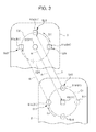
- FIG. 3 is a diagram schematically showing disposition positions of first light emitting units 51 and a second light receiving unit 62 in the operation unit side body 2 , as well as disposition positions of first light receiving units 61 and a second light emitting unit 52 in the display unit side body 3 ;
- FIG. 4 is a diagram showing a first circumference C 1 that is virtually developed into a linear shape along an extending direction D 1 thereof, and a second circumference C 2 that is virtually developed into a linear shape along an extending direction D 2 thereof;
- FIG. 5 is a diagram schematically showing the cellular telephone 1 in the closed state (in the first rotation position) ( FIG. 5 corresponds to FIG. 2 );
- FIG. 6 is a diagram showing a state (second rotation position) in which the display unit side body 3 is rotated 90 degrees anticlockwise to the operation unit side body 2 around the rotational axis 41 ;
- FIG. 7 is a diagram showing a state (third rotation position) in which the display unit side body 3 is rotated 180 degrees relative to the operation unit side body 2 around the rotational axis 41 ;
- FIG. 8 is a diagram showing a state (fourth rotation position) in which the display unit side body 3 is rotated 270 degrees anticlockwise to the operation unit side body 2 around the rotational axis 41 ;
- FIG. 9 is a functional block diagram showing functions of the cellular telephone of the first embodiment.
- FIG. 10 is a functional block diagram of a processing unit 70 .
- FIG. 11 is a diagram schematically showing a configuration for transmitting and receiving light in a cellular telephone of a second embodiment of the present invention ( FIG. 11 corresponds to FIG. 3 ).
- FIG. 1 is a front view showing a cellular telephone 1 according to a first embodiment of the present invention, in a state in which an operation unit side body 2 and a display unit side body 3 are opened.
- FIG. 2 is a front view showing the cellular telephone 1 shown in FIG. 1 , in a state in which the operation unit side body 2 and the display unit side body 3 are closed.
- the cellular telephone 1 includes the operation unit side body 2 that is a first body, and the display unit side body 3 that is a second body.
- the cellular telephone 1 of the present embodiment is a cellular telephone 1 of a so-called rotating type (turning type), in which one body can be rotated around a rotational axis 41 extending in a direction so as to superimpose the operation unit side body 2 and the display unit side body 3 (the direction penetrating the paper plane of FIGS. 1 and 2 ).
- rotating type turning type
- an upper end portion of the operation unit side body 2 and a lower end portion of the display unit side body 3 are connected via a connecting portion 4 including the rotational axis 41 so as to be rotatable around the rotational axis 41 .
- the cellular telephone 1 of the present embodiment is configured such that the operation unit side body 2 and the display unit side body 3 connected via the connecting portion 4 can be relatively moved.
- the cellular telephone 1 is configured so as to be capable of being switched between a state in which the operation unit side body 2 and the display unit side body 3 are opened (an opened state; see FIG. 1 ), and a state in which the operation unit side body 2 and the display unit side body 3 are closed (a closed state; see FIG. 2 ).
- the closed state is a state in which a front face 2 a of the operation unit side body 2 and a rear face 3 b (see FIG. 4 ) of the display unit side body 3 are superimposed with each other. States other than the closed state are referred to as the opened state.
- an external surface of the operation unit side body 2 is configured with: a front case 21 forming a front face 2 a side; and a rear case (not shown) forming a rear face side.
- the operation unit side body 2 is configured to expose, on the front case 21 side, an operation key set 11 and a sound input unit 12 as a microphone where the sound of the user of the cellular phone 1 is input when conversing.
- the operation key set 11 is configured with: function setting operation keys 13 for operating various functions such as for various settings, a telephone number directory function and a mail function; and input operation keys 14 for inputting digits of a telephone number, characters for mail, etc.; and a selection operation key 15 that performs selection of the various operations and scrolls up, down, left and right.
- Predetermined functions are assigned (key assignment) to each key configuring the operation key set 11 in accordance with the opened/closed state of the operation unit side body 2 and the display unit side body 3 , various modes, and the type of application that is running.
- An operation corresponding to a function assigned to each key is executed by the user depressing each key.
- the sound input unit 12 is disposed to an outer end side that is opposite to the connecting portion 4 side in a longitudinal direction of the operation unit side body 2 . In other words, the sound input unit 12 is disposed to an outer end side of the cellular telephone 1 in the opened state.
- An external surface of the display unit side body 3 is configured with: a front case 30 forming a front face 3 a side; and a rear case 32 forming a rear face 3 b side (see FIG. 4 ).
- the display unit side body 3 is configured with disposition to expose, on a front case 30 side, a main display unit 34 a for displaying a variety of information, and a sound output unit 31 for outputting sound of the other party of a conversation.
- each light emitting unit and each light receiving unit in the operation unit side body 2 and the display unit side body 3 are described with reference to FIGS. 3 and 4 .
- FIG. 3 is a diagram schematically showing disposition positions of first light emitting units 51 and a second light receiving unit 62 in the operation unit side body 2 , as well as disposition positions of first light receiving units 61 and a second light emitting unit 52 in the display unit side body 3 .
- FIG. 4 is a diagram showing a first circumference C 1 that is virtually developed into a linear shape along an extending direction D 1 thereof, and a second circumference C 2 that is virtually developed into a linear shape along an extending direction D 2 thereof.
- the first light emitting units 51 and the second light receiving unit 62 are mounted in the operation unit side body 2 .
- the first light emitting units 51 are portions that emit light R, and consist of, for example, a semiconductor device that emits light when a voltage is applied thereto.
- the first light emitting units 51 are disposed on the first circumference C 1 around the rotational axis 41 in the operation unit side body 2 .
- the second light receiving unit 62 is a portion that receives light, and consists of, for example, a photosensor.
- the second light receiving unit 62 is disposed in a position overlapping with the rotational axis 41 in the operation unit side body 2 .
- the first light receiving units 61 and the second light emitting unit 52 are mounted in the display unit side body 3 .
- the first light receiving units 61 are portions that receive light, and consist of, for example, a photosensor.
- the first light receiving units 61 are disposed on the second circumference C 2 in the display unit side body 3 .
- the second circumference C 2 has the rotational axis 41 as its center, and faces the first circumference C 1 .
- the second light emitting unit 52 is a portion that emits light, and consists of, for example, a semiconductor device that emits light when a voltage is applied thereto.
- the second light emitting unit 52 is disposed in a position overlapping with the rotational axis 41 and facing the second light receiving unit 62 in the display unit side body 3 .
- a rotation position detecting unit (a detecting unit) 71 is provided (see FIG. 6 ).
- the rotation position detecting unit 71 detects a rotation position of the display unit side body 3 relative to the operation unit side body 2 , by detecting presence or absence of light reception, in the first light receiving units 61 , of the light R emitted from the first light emitting units 51 .
- the rotation position detecting unit 71 is later described in detail.
- a configuration is employed such that the display unit side body 3 is held to the operation unit side body 2 in a plurality of rotation positions, in which a rotation angle ⁇ of the display unit side body 3 relative to the operation unit side body 2 is a multiple of a preset setting angle ⁇ .
- the setting angle ⁇ is an angle obtained by dividing 360 degrees by an integer.
- the setting angle ⁇ is 90 degrees. Therefore, there are four rotation positions of the display unit side body 3 relative to the operation unit side body 2 (see FIGS. 5 to 8 ).
- the rotation angle ⁇ is expressed as a rotation angle in an anticlockwise manner with the operation unit side body 2 serving as a reference point, in which the operation unit side body 2 is viewed from the display unit side body 3 .
- the rotation angle ⁇ is 90 degrees (see FIG. 6 ).
- the rotation angle ⁇ is 270 degrees (see FIG. 8 ).
- the first light emitting unit(s) 51 is disposed in a part or all of the plurality of positions on the first circumference C 1 such that the angle thereof is a multiple of the setting angle ⁇ .
- the first circumference C 1 is a virtual circumference on which the first light emitting units 51 are positioned.
- a position on an upper end portion side (an upper side thereof in FIG. 3 ) in the operation unit side body 2 from the rotational axis 41 is referred to as a “second position S 12 ”.
- a position on a lower end portion side (a lower side thereof in FIG. 3 ) in the operation unit side body 2 from the rotational axis 41 is referred to as a “fourth position S 14 ”.
- a position of being displaced 90 degrees clockwise from the second position S 12 is referred to as a “first position S 11 ”.
- a position of being displaced 90 degrees anticlockwise from the second position S 12 is referred to as a “third position S 13 ”.
- the first light emitting units 51 is used when providing a description that is common to each of the first light emitting units.
- an expression such as a “first light emitting unit 51 b ” and a “first light emitting unit 51 c ” is used.
- the first light emitting unit 51 b is disposed in the second position S 12
- the first light emitting unit 51 c is disposed in the third position S 13 .
- the plurality of the first light emitting units 51 are adjacently disposed.
- the first light emitting units 51 are not disposed in the first position S 11 and the fourth position S 14 . It should be noted that the first position S 11 and the fourth position S 14 are indicated with a two-dot chain line in FIG. 3 .
- the first light receiving unit(s) 61 is disposed in a part or all of the plurality of positions on the second circumference C 2 such that the angle thereof is a multiple of the setting angle ⁇ .
- the second circumference C 2 is a virtual circumference on which the first light receiving units 61 are positioned.
- a position on an upper end portion side (an upper side thereof in FIG. 3 ) in the display unit side body 3 from the rotational axis 41 is referred to as a “second position S 22 ”.
- a position on a lower end portion side (a lower side thereof in FIG. 3 ) in the display unit side body 3 from the rotational axis 41 is referred to as a “fourth position S 24 ”.
- first position S 21 A position of being displaced 90 degrees anticlockwise from the second position S 22 is referred to as a “third position S 23 ”.
- the first light receiving units 61 is used when providing a description that is common to each of the first light receiving units.
- an expression such as a “first light receiving unit 61 a ”, a “first light receiving unit 61 b ” and a “first light receiving unit 61 c ” is used.
- the first light receiving unit 61 a is disposed in the first position S 21
- the first light receiving unit 61 b is disposed in the second position S 22
- the first light receiving unit 61 c is disposed in the third position S 23 .
- the plurality of the first light receiving units 61 are adjacently disposed.
- the first light receiving unit 61 is not disposed in the fourth position S 24 .
- the fourth position S 24 is indicated with a two-dot chain line in FIG. 3 .
- first open holes 22 are provided in positions corresponding to the first position S 11 , the second position S 12 , the third position S 13 and the fourth position S 14 on the first circumference C 1 , respectively. Therefore, the first light emitting units 51 are exposed on the front face 2 a side of the operation unit side body 2 through the first open holes 22 .
- the first light receiving units 61 are exposed on the rear face 3 b side of the display unit side body 3 through the second open holes 33 .
- the first light receiving units 61 receive the light R emitted from the first light emitting units 51 , thereby transmitting a signal from the operation unit side body 2 to the display unit side body 3 .
- the second light receiving unit 62 receives the light R emitted from the second light emitting unit 52 , thereby transmitting a signal from the display unit side body 3 to the operation unit side body 2 .
- a configuration is employed such that, when the display unit side body 3 is rotated relative to the operation unit side body 2 around the rotational axis 41 , the display unit side body 3 is held to the operation unit side body 2 in positions in which the rotation angle ⁇ of the display unit side body 3 relative to the operation unit side body 2 is a multiple of the preset setting angle ⁇ .
- FIG. 5 is a diagram schematically showing the cellular telephone 1 in the closed state (in the first rotation position) ( FIG. 5 corresponds to FIG. 2 ).
- FIG. 6 is a diagram showing a state (second rotation position) in which the display unit side body 3 is rotated 90 degrees anticlockwise to the operation unit side body 2 around the rotational axis 41 .
- FIG. 7 is a diagram showing a state (third rotation position) in which the display unit side body 3 is rotated 180 degrees relative to the operation unit side body 2 around the rotational axis 41 .
- FIG. 8 is a diagram showing a state (fourth rotation position) in which the display unit side body 3 is rotated 270 degrees anticlockwise to the operation unit side body 2 around the rotational axis 41 .
- a configuration is employed such that the display unit side body 3 is held to the operation unit side body 2 in rotation positions in which the rotation angle ⁇ of the display unit side body 3 relative to the operation unit side body 2 is a multiple of 90 degrees (0, 90, 180 or 270 degrees).
- the configuration for holding the display unit side body 3 to the operation unit side body 2 is not particularly limited, and various holding means can be utilized.
- the first light emitting units 51 are disposed such that a disposition pattern of the first light emitting unit 51 in any rotation position of (the plurality of) the first, second, third and fourth rotation positions is not the same disposition pattern as a disposition pattern of the first light emitting unit 51 in another rotation position of the plurality of rotation positions.
- a disposition pattern of the first light emitting unit 51 is expressed by which of the plurality of positions (S 21 , S 22 , S 23 , S 24 ) is faced by the first light emitting unit 51 in each rotation position, in which the angle thereof is a multiple of the setting angle ⁇ on the second circumference C 2 .
- positions faced by the two first light emitting units 51 b and 51 c on the second circumference C 2 are the positions S 22 and S 23 , respectively. Accordingly, this disposition pattern is expressed as a pattern (S 22 , S 23 ).
- a disposition pattern of the first light emitting units 51 is a pattern (S 21 , S 22 ).
- a disposition pattern of the first light emitting units 51 is a pattern (S 24 , S 21 ).
- a disposition pattern of the first light emitting units 51 is a pattern (S 23 , S 24 ). In this way, the disposition patterns of the first light emitting units 51 are all different among each rotation position.
- the disposition patterns of the first light emitting units 51 in different rotation positions are the same disposition pattern
- two of the first light emitting units 51 may be in positions facing each other on the second circumference C 2 .
- the disposition patterns of the first light emitting units 51 may be a pattern (S 22 , S 24 ) and a pattern (S 24 , S 22 )
- the disposition patterns of the first light emitting units 51 may be a pattern (S 21 , S 23 ) and a pattern (S 23 , S 21 ).
- the pattern (S 22 , S 24 ) and the pattern (S 24 , S 22 ) are the same disposition pattern.
- the pattern (S 21 , S 23 ) and the pattern (S 23 , S 21 ) are the same disposition pattern. This is because of a presupposition that the plurality of the first light emitting units 51 b and 51 c are substantially the same type of the first light emitting units 51 , i.e. on the first light receiving unit 61 side, it is not possible to distinguish which of the first light emitting units 51 has emitted the light.
- an integer obtained by dividing 360 degrees by the setting angle ⁇ is an integer N
- a number of the first light emitting units 51 disposed in positions on the first circumference C 1 such that the angle thereof is a multiple of the setting angle ⁇ is a first number L
- a number of the first light receiving units 61 disposed in positions on the second circumference C 2 such that the angle thereof is a multiple of the setting angle ⁇ is a second number R
- the integer N, the first number L and the second number R satisfy the relationship expressed by the following formulae 1 and 2.
- the (first) number L of the first light emitting units 51 on the first circumference C 1 is two.
- the (second) number R of the first light receiving units 61 on the second circumference C 2 is three.
- the integer N, the first number L and the second number R further satisfy the relationship expressed by the formula 3 shown below.
- L+R ⁇ N+ 1 Formula 3 L+R ⁇ N+ 1 Formula 3:
- the first position S 11 , the second position S 12 , the third position S 13 and the fourth position S 14 in the operation unit side body 2 face the first position S 21 , the second position S 22 , the third position S 23 and the fourth position S 24 in the display unit side body 3 , respectively.
- first light emitting unit 51 b positioned in the second position S 12 in the operation unit side body 2 faces in the first light receiving unit 61 b positioned in the second position S 22 in the display unit side body 3 .
- the first light emitting unit 51 c positioned in the third position S 13 in the operation unit side body 2 faces the first light receiving unit 61 c positioned in the third position S 23 in the display unit side body 3 .
- the first light emitting unit 51 does not exist in the first position S 11 in the operation unit side body 2 ; therefore, the first light receiving unit 61 a positioned in the first position S 21 in the display unit side body 3 does not face the first light emitting unit 51 .
- the light R emitted from the first light emitting unit 51 b positioned in the second position S 12 is received by the first light receiving unit 61 b positioned in the second position S 22 .
- the light R emitted from the first light emitting unit 51 c positioned in the third position S 13 is received by the first light receiving unit 61 c positioned in the third position S 23 .
- the light R emitted from the second light emitting unit 52 positioned in a position overlapping with the rotational axis 41 in the display unit side body 3 is received by the second light receiving unit 62 positioned in a position overlapping with the rotational axis 41 in the operation unit side body 2 .
- the light R emitted from the second light emitting unit 52 is received by the second light receiving unit 62 .
- one propagation path of the light R is formed.
- the first light emitting unit 51 b coincides (overlaps) with the first light receiving unit 61 a
- the first light emitting unit 51 c coincides (overlaps) with the first light receiving unit 61 b.
- the second light emitting unit 52 coincides (overlaps) with the second light receiving unit 62 regardless of the rotation angle ⁇ of the display unit side body 3 relative to the operation unit side body 2 .
- the light R emitted from the first light emitting units 51 is received by the first light receiving units 61 .
- two propagation paths of the light R are formed.
- the second opposed light emitting unit 52 and the second light receiving unit 62 facing each other the light R emitted from the second light emitting unit 52 is received by the second light receiving unit 62 .
- one propagation path of the light R is formed.
- the first light emitting unit 51 c coincides (overlaps) with the first light receiving unit 61 a.
- the second light emitting unit 52 coincides (overlaps) with the second light receiving unit 62 regardless of the rotation angle ⁇ of the display unit side body 3 relative to the operation unit side body 2 .
- the first light emitting unit 51 b does not coincide (overlap) with the first light receiving unit 61 .
- the light R emitted from the first light emitting unit 51 is received by the first light receiving unit 61 .
- one propagation path of the light R is formed.
- the second opposed light emitting unit 52 and the second light receiving unit 62 facing each other the light R emitted from the second light emitting unit 52 is received by the second light receiving unit 62 .
- one propagation path of the light R is formed.
- the first light emitting unit 51 b coincides (overlaps) with the first light receiving unit 61 c.
- the second light emitting unit 52 coincides (overlaps) with the second light receiving unit 62 regardless of the rotation angle ⁇ of the display unit side body 3 relative to the operation unit side body 2 .
- the first light emitting unit 51 c does not coincide (overlap) with the first light receiving unit 61 .
- the light R emitted from the first light emitting unit 51 is received by the first light receiving unit 61 .
- one propagation path of the light R is formed.
- the second opposed light emitting unit 52 and the second light receiving unit 62 facing each other the light R emitted from the second light emitting unit 52 is received by the second light receiving unit 62 .
- one propagation path of the light R is formed.
- the display unit side body 3 when the display unit side body 3 is disposed in any of the first to fourth rotation positions shown in FIGS. 5 to 8 , respectively, the light R emitted from the first light emitting units 51 is received by the first light receiving units 61 . In other words, a signal is communicated by way of propagation of the light R. Therefore, in the middle of communication from one signal communication position to another signal communication position, the communication of the signal is interrupted. In this case, before interrupting transmission and reception of the light signal, in order to detect that the position of the display unit side body 3 has been changed, it is preferable that an encoder with superior detection accuracy is used, or output differences of a plurality of sensors are compared, thereby detecting the rotation position of the display unit side body 3 . Moreover, in a case in which the signal communication has been interrupted, the receiving side may request the transmitting side to retransmit the interrupted signal.
- FIG. 9 is a functional block diagram showing functions of the cellular telephone of the first embodiment.
- FIG. 10 is a functional block diagram of a processing unit 70 .
- the cellular telephone of the first embodiment includes: a main display unit 34 a that displays predetermined information; a sub display unit 36 a (not shown in FIGS. 1 and 2 ) that displays predetermined information; a communication unit 80 that communicates with external terminals; a processing unit 70 that performs predetermined processing; a rechargeable battery 91 having a predetermined capacity; a power supply circuit unit 90 that converts a power supply voltage supplied from the rechargeable battery 91 into a predetermined power voltage, and supplies the converted power supply voltage to the communication unit 80 , the processing unit 70 , etc.; and a storage unit 100 .
- the communication unit 80 includes: a main antenna 81 that communicates with external devices via a predetermined usable frequency band; and a communication processing unit 82 that performs signal processing such as modulation processing and demodulation processing.
- the main antenna 81 communicates with external devices (base stations) via a predetermined usable frequency band (for example, 800 MHz).
- a predetermined usable frequency band for example, 800 MHz.
- the communication processing unit 82 performs demodulation processing of a signal received by the main antenna 81 , and transmits the processed signal to the processing unit 70 .
- the communication processing unit 82 performs modulation processing of the signal transmitted from the processing unit 70 , and transmits the signal to external devices (base stations) via the main antenna 81 .
- the power supply circuit unit 90 converts a power supply voltage supplied from the rechargeable battery 91 into a predetermined power voltage, and supplies the converted power supply voltage to the communication unit 80 , the processing unit 70 , etc.
- the storage unit 100 stores a multitude of programs to be executed by the processing unit 70 , as well as parameters, various tables, etc. More specifically, the storage unit 100 stores, for example, a table 110 , in addition to a multitude of application programs and the like controlled by a control unit 72 (to be described later).
- the table 110 indicates, for example, a correspondence relationship between the patterns of presence or absence of light reception in the first light receiving units 61 , and the rotation positions of the display unit side body 3 relative to the operation unit side body 2 .
- the table 110 indicates a correspondence relationship between each rotation position detected by a rotation position detecting unit 71 (to be described later) and predetermined behavior corresponding to each rotation position.
- the processing unit 70 performs predetermined processing. As shown in FIG. 10 , the processing unit 70 includes the rotation position detecting unit 71 and the control unit 72 .
- the rotation position detecting unit 71 detects a rotation position of the display unit side body 3 relative to the operation unit side body 2 .
- the control unit 72 activates a predetermined application that causes predetermined behavior corresponding to a rotation position detected by the rotation position detecting unit 71 to function, and controls the predetermined application thus activated.
- the rotation position detecting unit 71 detects a rotation position of the display unit side body 3 relative to the operation unit side body 2 as follows.
- the rotation position detecting unit 71 refers to the table 110 in the storage unit 100 to detect that the rotation position of the display unit side body 3 relative to the operation unit side body 2 is the “first position”.
- the rotation position detecting unit 71 refers to the table 110 in the storage unit 100 to detect that the rotation position of the display unit side body 3 relative to the operation unit side body 2 is the “second position”.
- the rotation position detecting unit 71 refers to the table 110 in the storage unit 100 to detect that the rotation position of the display unit side body 3 relative to the operation unit side body 2 is the “third position”.
- the rotation position detecting unit 71 refers to the table 110 in the storage unit 100 to detect that the rotation position of the display unit side body 3 relative to the operation unit side body 2 is the “fourth position”.
- the control unit 72 then refers to the table 110 in the storage unit 100 , activates a predetermined application that causes predetermined behavior to function, and operates a function to control the predetermined application thus activated, depending on which of the “first rotation position”, the “second rotation position”, the “third rotation position” or the “fourth rotation position” is the rotation position of the display unit side body 3 relative to the operation unit side body 2 .
- the cellular telephone 1 of the first embodiment includes the rotation position detecting unit 71 that detects a rotation position of the display unit side body 3 relative to the operation unit side body 2 by detecting presence or absence of light reception, in the first light receiving units 61 , of the light R emitted from the first light emitting units 51 .
- the first light emitting units 51 are disposed on the first circumference C 1 in the operation unit side body 2 .
- the first light receiving units 61 are disposed on the second circumference C 2 in the display unit side body 3 .
- a relative rotation position between the two bodies 2 and 3 can be optically detected, without utilizing a difference of reflection efficiency in a plurality of reflecting portions. Therefore, influence due to deterioration of the reflection efficiency in the reflecting portions is not suffered.
- the first light emitting units 51 are disposed on the first circumference C 1
- the first light receiving units 61 are disposed on the second circumference C 2 ; therefore, a plurality of desired rotation positions can be easily detected.
- the display unit side body 3 is held to the operation unit side body 2 in a plurality of positions, in which the rotation angle ⁇ of the display unit side body 3 relative to the operation unit side body 2 is a multiple of the preset setting angle ⁇ .
- the first light emitting unit(s) 51 is disposed in a part or all of the plurality of positions (the first position S 11 , the second position S 12 , the third position S 13 and the fourth position S 14 ) on the first circumference C 1 such that the angle thereof is a multiple of the setting angle ⁇ .
- the first light receiving units 61 do not have to determine which of the plurality of the first light emitting units 51 has emitted the light.
- a rotation position of the display unit side body 3 relative to the operation unit side body 2 can be detected only by the first light receiving unit 61 determining presence or absence of light reception.
- the first light receiving units 61 receive the light emitted from the first light emitting units 51 , thereby transmitting a signal from the operation unit side body 2 to the display unit side body 3 .
- the light for detecting a rotation position is utilized for communicating a signal, thereby making it possible to achieve size reduction of the entire cellular telephone 1 , as compared to a case of separately providing a configuration for communicating the light.
- the first embodiment further includes the second light emitting unit 52 and the second light receiving unit 62 , and the second light receiving unit 62 receives the light emitted from the second light emitting unit 52 , thereby transmitting a signal from the display unit side body 3 to the operation unit side body 2 . Therefore, bidirectional signal communication utilizing the light is enabled between the operation unit side body 2 and the display unit side body 3 .
- FIG. 11 is a diagram schematically showing a configuration for transmitting and receiving light in a cellular telephone of the second embodiment of the present invention ( FIG. 11 corresponds to FIG. 3 ).
- the second embodiment is mainly different from the first embodiment in that the light emitting units and the light receiving units are provided on the circumference around the rotational axis 41 in both of the operation unit side body 2 and the display unit side body 3 . More specifically, the second embodiment is different from the first embodiment in that third light emitting units 53 are further provided on a third circumference C 3 in the display unit side body 3 , and third light receiving units 63 are further provided on a fourth circumference C 4 in the operation unit side body 2 .
- the second embodiment is described mainly in terms of differences from the first embodiment.
- the description regarding the first embodiment is applied as appropriate where no description is particularly provided regarding the second embodiment.
- a configuration similar to that in the first embodiment is assigned with the same reference numeral, or an apostrophe is appended to the reference numeral.
- the second embodiment includes an operation unit side body 2 ′, a display unit side body 3 ′, and a processing unit 70 ′ (not shown) including a rotation position detecting unit 71 ′.
- the first light emitting units 51 ( 51 b, 51 c ) that emit light, the second light receiving unit 62 that receives light, and the third light receiving units 63 ( 63 a, 63 b, 63 c ) that receive light are mounted in the operation unit side body 2 ′.
- the third light emitting units 53 ( 53 b, 53 c ) that emit light, the second light emitting unit 52 that emits light, and the first light receiving units 61 ( 61 a, 61 b, 61 c ) that receive light are mounted in the display unit side body 3 ′.
- the second light receiving unit 62 is disposed in a position overlapping with the rotational axis 41 in the operation unit side body 2 .
- the first light receiving units 61 are disposed on the second circumference C 2 around the rotational axis 41 and facing the first circumference C 1 in the display unit side body 3 .
- the third light emitting units 53 are disposed on the third circumference C 3 around the rotational axis 41 in the display unit side body 3 .
- the second light emitting unit 52 is disposed in a position overlapping with the rotational axis 41 and facing the second light receiving unit 62 in the display unit side body 3 .
- the third light receiving units 63 are disposed on the fourth circumference C 4 around the rotational axis 41 and facing the third circumference C 3 in the operation unit side body 2 .
- the rotation position detecting unit 71 ′ detects a rotation position of the display unit side body 3 relative to the operation unit side body 2 , and transmits and receives a signal between the operation unit side body 2 and the display unit side body 3 .
- the processing unit 70 ′ including the rotation position detecting unit 71 ′ has a configuration similar to, and performs behavior similar to, those of the processing unit 70 in the first embodiment.
- the third light emitting units 53 and the third light receiving units 63 in the second embodiment are described.
- the third light emitting unit(s) 53 is disposed in a part or all of the plurality of positions on the third circumference C 3 such that the angle thereof is a multiple of the setting angle ⁇ .
- the third circumference C 3 is a virtual circumference on which the third light emitting units 53 are positioned.
- a position on an upper end portion side (an upper side thereof in FIG. 11 ) in the display unit side body 3 from the rotational axis 41 is referred to as a “second position S 32 ”.
- a position on a lower end portion side (a lower side thereof in FIG. 11 ) in the display unit side body 3 from the rotational axis 41 is referred to as a “fourth position S 34 ”.
- a position of being displaced 90 degrees clockwise from the second position S 32 is referred to as a “first position S 31 ”.
- a position of being displaced 90 degrees anticlockwise from the second position S 32 is referred to as a “third position S 33 ”.
- the third light emitting units 53 is used when providing a description that is common to each of the third light emitting units.
- an expression such as a “third light emitting unit 53 b ” and a “third light emitting unit 53 c ” is used.
- the third light emitting unit 53 b is disposed in the second position S 32 .
- the third light emitting unit 53 c is disposed in the third position S 33 .
- the plurality of the third light emitting units 53 are adjacently disposed.
- the third light emitting units 53 are not disposed in the first position S 31 and the fourth position S 34 . It should be noted that the first position S 31 and the fourth position S 34 are indicated with a two-dot chain line in FIG. 11 .
- the third light receiving unit(s) 63 is disposed in a part or all of the plurality of positions on the fourth circumference C 4 such that the angle thereof is a multiple of the setting angle ⁇ .
- the fourth circumference C 4 is a virtual circumference on which the third light receiving units 63 are positioned.
- On the fourth circumference C 41 a position on an upper end portion side (an upper side thereof in FIG. 11 ) in the operation unit side body 2 from the rotational axis 41 is referred to as a “second position S 42 ”.
- a position on a lower end portion side (a lower side thereof in FIG. 11 ) in the operation unit side body 2 from the rotational axis 41 is referred to as a “fourth position S 44 ”.
- a position of being displaced 90 degrees clockwise from the second position S 42 is referred to as a “first position S 41 ”.
- a position of being displaced 90 degrees anticlockwise from the second position S 42 is referred to as a “third position S 43 ”.
- the third light receiving units 63 is used when providing a description that is common to each of the third light receiving units.
- an expression such as a “third light receiving unit 63 a ”, a “third light receiving unit 63 b ” and a “third light receiving unit 63 c ” is used.
- the first light receiving unit 63 a is disposed in the first position S 41
- the first light receiving unit 63 b is disposed in the second position S 42
- the first light receiving unit 63 c is disposed in the third position S 43 .
- the plurality of the third light receiving units 63 are adjacently disposed.
- the third light receiving unit 63 is not disposed in the fourth position S 44 . It should be noted that the fourth position S 44 is indicated with a two-dot chain line in FIG. 11 .
- the first light receiving units 61 receive the light R emitted from the first light emitting units 51 , thereby transmitting a signal from the operation unit side body 2 to the display unit side body 3 .
- the third light receiving units 63 receive the light R emitted from the third light emitting units 53 , thereby transmitting a signal from the display unit side body 3 to the operation unit side body 2 .
- the second light receiving unit 62 receives the light R emitted from the second light emitting unit 52 , thereby transmitting a signal from the display unit side body 3 to the operation unit side body 2 .
- the effects similar to those of the first embodiment are achieved, and in addition, the bidirectional signal communication utilizing the light is further facilitated between the operation unit side body 2 and the display unit side body 3 .
- the operation unit side body 2 is the first body (in other words, the first light emitting units 51 are provided to the operation unit side body 2 ), and the display unit side body 3 is the second body (in other words, the first light receiving units 61 are provided to the display unit side body 3 ); however, it is not limited thereto.
- the operation unit side body 2 may be the second body (in other words, the first light receiving units 61 are provided to the operation unit side body 2 ), and the display unit side body 3 may be the first body (in other words, the first light emitting units 51 are provided to the display unit side body 3 ).
- a light receiving/emitting element having both a light emitting function and a light reception function can be used.
- the light emitted from a light receiving/emitting element in the operation unit side body 2 can be received by a light receiving/emitting element in the display unit side body 3
- the light emitted from the light receiving/emitting element in the display unit side body 3 can be received by the light receiving/emitting element in the operation unit side body 2 .
- the setting angle ⁇ is 90 degrees in the first and second embodiments, it is not limited thereto.
- the setting angle ⁇ may be, for example, 180 degrees, 120 degrees, 72 degrees, 60 degrees, 45 degrees or 30 degrees.
- N, L, R (3,1,2), (3,1,3), (3,2,2), (3,2,3)
- N, L, R (4,1,3), (4,1,4), (4,2,2), (4,2,3), (4,2,4), (4,3,3), (4,3,4)
- N, L, R (5,1,4), (5,1,5), (5,2,3), (5,2,4), (5,2,5), (5,3,3), (5,3,4), (5,3,5), (5,4,4), (5,4,5)
- N, L, R (6,1,5), (6,1,6), (6,2,4), (6,2,5), (6,2,6), (6,3,3), (6,3,4), (6,3,5), (6,3,6), (6,4,4), (6,4,5), (6,4,6), (6,5,5), (6,5,6)
- Disposition examples (examples 1 to 5) of the first light emitting units 51 , the first light receiving units 61 , the third light emitting units 53 and the third light receiving units 63 in a case in which the setting angle ⁇ is 90 degrees are described as follows (Table 1). It should be noted that, in Table 1, a symbol “ ⁇ ” denotes that the first light emitting units 51 , etc. are disposed. A symbol “ ⁇ ” or “ ⁇ ” denotes that the first light emitting units 51 , etc. are not disposed.
- Example 1 is an example in which the first light emitting unit 51 is disposed only in the position S 12 , and the first light emitting units 51 are not disposed in the positions S 11 , S 13 and S 14 ; and the first light receiving units 61 are disposed in the positions S 21 , S 22 and S 23 , and the first light receiving unit 61 is not disposed in the position S 24 (it should be noted that the third light emitting units 53 and the third light receiving units 63 are not provided).
- the second light emitting units 52 and the second light receiving units 62 may be further provided, or the second light emitting units 52 and the second light receiving units 62 may not be provided.
- the third light emitting units 53 and the third light receiving units 63 can be further provided in the disposition positions similar to the disposition example of the first light emitting units 51 and the first light receiving units 61 .
- the present invention is not limited thereto.
- the present invention can be applied to an opening-and-closing type (hinge type) in which the display unit side body 3 and the operation unit side body 2 are connected so as to be rotatable (openable and closable) around the rotational axis extending in the width direction thereof, thereby making it possible to detect a rotation position in the opening-and-closing type as well.
- the electric circuit wiring may include, for example: operation unit side power supply wiring being connected to a power supply provided to the operation unit side body 2 , and being disposed in the center of the rotational axis 41 ; and operation unit side power supply wiring being disposed in the center of the rotational axis 41 , and being rotatably in contact with the operation unit side power supply wiring.
- the electronic device of the present invention can be applied to electronic devices other than a cellular telephone.
- Electronic devices other than a cellular telephone may include, for example, PHS (registered trademark: Personal Handyphone System), portable gaming machines, portable navigation devices, PDA (Personal Digital Assistant), notebook computers, and EL displays or liquid crystal displays equipped with an operation unit.
- PHS Personal Handyphone System
- portable gaming machines portable gaming machines
- portable navigation devices portable navigation devices
- PDA Personal Digital Assistant
- notebook computers Portable EL displays or liquid crystal displays equipped with an operation unit.
Landscapes
- Engineering & Computer Science (AREA)
- Physics & Mathematics (AREA)
- General Physics & Mathematics (AREA)
- Theoretical Computer Science (AREA)
- Computer Hardware Design (AREA)
- General Engineering & Computer Science (AREA)
- Human Computer Interaction (AREA)
- Signal Processing (AREA)
- Mathematical Physics (AREA)
- Telephone Set Structure (AREA)
- Pivots And Pivotal Connections (AREA)
- Length Measuring Devices By Optical Means (AREA)
- Optical Transform (AREA)
Abstract
Description
L≦R≦N formula 1:
N≦L+R≦2N−1. formula 2:
L+R≧N+1. formula 3:
L≦R≦N Formula 1:
N≦L+R≦2N−1 Formula 2:
2≦3≦4 Formula 1:
4≦2+3≦2*4−1 Formula 2:
L+R≧N+1 Formula 3:
2+3≧4+1 Formula 3:
L≦R≦N Formula 1:
N≦L+R≦2N−1 Formula 2:
L+R≧N+1 Formula 3:
(N, L, R)=(2,1,1), (2,1,2)
(N, L, R)=(3,1,2), (3,1,3), (3,2,2), (3,2,3)
(N, L, R)=(4,1,3), (4,1,4), (4,2,2), (4,2,3), (4,2,4), (4,3,3), (4,3,4)
(N, L, R)=(5,1,4), (5,1,5), (5,2,3), (5,2,4), (5,2,5), (5,3,3), (5,3,4), (5,3,5), (5,4,4), (5,4,5)
(N, L, R)=(6,1,5), (6,1,6), (6,2,4), (6,2,5), (6,2,6), (6,3,3), (6,3,4), (6,3,5), (6,3,6), (6,4,4), (6,4,5), (6,4,6), (6,5,5), (6,5,6)
| TABLE 1 | ||||||
| Example | Example | Example | Example | | Example | |
| Position | ||||||
| 1 | 2 | 3 | 4 | 5 | 6 | |
| S11 | X | X | X | X | ◯ | ◯ |
| S12 | ◯ | ◯ | ◯ | ◯ | ◯ | ◯ |
| S13 | X | X | ◯ | ◯ | ◯ | ◯ |
| S14 | X | X | X | X | X | X |
| S21 | ◯ | ◯ | X | ◯ | ◯ | ◯ |
| S22 | ◯ | ◯ | ◯ | ◯ | ◯ | ◯ |
| S23 | ◯ | ◯ | ◯ | ◯ | ◯ | ◯ |
| S24 | X | ◯ | X | ◯ | X | X |
| S31 | — | — | — | — | — | ◯ |
| S32 | — | — | — | — | — | ◯ |
| S33 | — | — | — | — | — | ◯ |
| S34 | — | — | — | — | — | X |
| S41 | — | — | — | — | — | ◯ |
| S42 | — | — | — | — | — | ◯ |
| S43 | — | — | — | — | — | ◯ |
| S44 | — | — | — | — | — | X |
Claims (6)
L≦R≦N formula 1:
N≦L+R≦2N−1. formula 2:
L+R≧N+1. formula 3:
Applications Claiming Priority (3)
| Application Number | Priority Date | Filing Date | Title |
|---|---|---|---|
| JP2008-140334 | 2008-05-29 | ||
| JP2008140334A JP5166123B2 (en) | 2008-05-29 | 2008-05-29 | Portable electronic devices |
| PCT/JP2009/059791 WO2009145265A1 (en) | 2008-05-29 | 2009-05-28 | Electronic device |
Publications (2)
| Publication Number | Publication Date |
|---|---|
| US20110105201A1 US20110105201A1 (en) | 2011-05-05 |
| US8311596B2 true US8311596B2 (en) | 2012-11-13 |
Family
ID=41377135
Family Applications (1)
| Application Number | Title | Priority Date | Filing Date |
|---|---|---|---|
| US12/994,467 Expired - Fee Related US8311596B2 (en) | 2008-05-29 | 2009-05-28 | Electronic device with rotational position determination unit |
Country Status (5)
| Country | Link |
|---|---|
| US (1) | US8311596B2 (en) |
| JP (1) | JP5166123B2 (en) |
| KR (1) | KR101189426B1 (en) |
| CN (1) | CN102037311B (en) |
| WO (1) | WO2009145265A1 (en) |
Cited By (1)
| Publication number | Priority date | Publication date | Assignee | Title |
|---|---|---|---|---|
| US20150156304A1 (en) * | 2012-07-05 | 2015-06-04 | Lenovo (Beijing) Co., Ltd. | Electronic Device And Information Processing Method |
Families Citing this family (3)
| Publication number | Priority date | Publication date | Assignee | Title |
|---|---|---|---|---|
| USD752459S1 (en) * | 2014-06-17 | 2016-03-29 | Fluke Corporation | Case enclosure |
| CN111586216B (en) * | 2020-04-30 | 2021-06-25 | 维沃移动通信有限公司 | Folding terminal, folding state determination method and apparatus, and computer-readable storage medium |
| CN112304252B (en) * | 2020-10-30 | 2022-03-22 | 维沃移动通信有限公司 | Folding angle determination method, folding device and electronic device |
Citations (10)
| Publication number | Priority date | Publication date | Assignee | Title |
|---|---|---|---|---|
| US20040266477A1 (en) | 2003-06-30 | 2004-12-30 | Casio Computer Co., Ltd. | Handheld electronic apparatus |
| US20050049017A1 (en) | 2003-08-29 | 2005-03-03 | Kyocera Corporation | Portable terminal device |
| JP2005064843A (en) | 2003-08-12 | 2005-03-10 | Kyocera Corp | Mobile terminal device |
| JP2005078322A (en) | 2003-08-29 | 2005-03-24 | Kyocera Corp | Mobile terminal device |
| US20050079898A1 (en) * | 2003-09-16 | 2005-04-14 | Hyung-Hoon Park | Slide-type mobile communication terminal |
| JP2005107976A (en) | 2003-09-30 | 2005-04-21 | Kyocera Corp | Portable terminal device and connecting member thereof |
| JP2005107074A (en) | 2003-09-30 | 2005-04-21 | Casio Comput Co Ltd | Portable electronic devices |
| JP2005295228A (en) | 2004-03-31 | 2005-10-20 | Casio Comput Co Ltd | Portable electronic devices |
| JP2007235722A (en) | 2006-03-02 | 2007-09-13 | Nec Corp | Foldable type portable electronic apparatus |
| US20070287504A1 (en) * | 2006-06-07 | 2007-12-13 | Lg Electronics Inc. | Mobile terminal |
-
2008
- 2008-05-29 JP JP2008140334A patent/JP5166123B2/en not_active Expired - Fee Related
-
2009
- 2009-05-28 CN CN2009801185290A patent/CN102037311B/en not_active Expired - Fee Related
- 2009-05-28 WO PCT/JP2009/059791 patent/WO2009145265A1/en not_active Ceased
- 2009-05-28 US US12/994,467 patent/US8311596B2/en not_active Expired - Fee Related
- 2009-05-28 KR KR1020107029258A patent/KR101189426B1/en not_active Expired - Fee Related
Patent Citations (12)
| Publication number | Priority date | Publication date | Assignee | Title |
|---|---|---|---|---|
| US20040266477A1 (en) | 2003-06-30 | 2004-12-30 | Casio Computer Co., Ltd. | Handheld electronic apparatus |
| CN1578325A (en) | 2003-06-30 | 2005-02-09 | 卡西欧计算机株式会社 | Handheld electronic apparatus |
| JP2005064843A (en) | 2003-08-12 | 2005-03-10 | Kyocera Corp | Mobile terminal device |
| US20050049017A1 (en) | 2003-08-29 | 2005-03-03 | Kyocera Corporation | Portable terminal device |
| CN1592318A (en) | 2003-08-29 | 2005-03-09 | 京瓷株式会社 | Portable terminal device |
| JP2005078322A (en) | 2003-08-29 | 2005-03-24 | Kyocera Corp | Mobile terminal device |
| US20050079898A1 (en) * | 2003-09-16 | 2005-04-14 | Hyung-Hoon Park | Slide-type mobile communication terminal |
| JP2005107976A (en) | 2003-09-30 | 2005-04-21 | Kyocera Corp | Portable terminal device and connecting member thereof |
| JP2005107074A (en) | 2003-09-30 | 2005-04-21 | Casio Comput Co Ltd | Portable electronic devices |
| JP2005295228A (en) | 2004-03-31 | 2005-10-20 | Casio Comput Co Ltd | Portable electronic devices |
| JP2007235722A (en) | 2006-03-02 | 2007-09-13 | Nec Corp | Foldable type portable electronic apparatus |
| US20070287504A1 (en) * | 2006-06-07 | 2007-12-13 | Lg Electronics Inc. | Mobile terminal |
Non-Patent Citations (4)
| Title |
|---|
| Communication from foreign patent office for a counterpart foreign application, dated Mar. 27, 2012. |
| English translation of foreign patent office communication of Mar. 27, 2012. |
| Equivalent English abstract for CN 1578325 A. |
| Equivalent English abstract for CN 1592318 A. |
Cited By (2)
| Publication number | Priority date | Publication date | Assignee | Title |
|---|---|---|---|---|
| US20150156304A1 (en) * | 2012-07-05 | 2015-06-04 | Lenovo (Beijing) Co., Ltd. | Electronic Device And Information Processing Method |
| US9270802B2 (en) * | 2012-07-05 | 2016-02-23 | Lenovo (Beijing) Co., Ltd. | Electronic device and information processing method |
Also Published As
| Publication number | Publication date |
|---|---|
| KR20110021973A (en) | 2011-03-04 |
| US20110105201A1 (en) | 2011-05-05 |
| JP5166123B2 (en) | 2013-03-21 |
| WO2009145265A1 (en) | 2009-12-03 |
| CN102037311B (en) | 2013-04-03 |
| KR101189426B1 (en) | 2012-10-10 |
| JP2009290506A (en) | 2009-12-10 |
| CN102037311A (en) | 2011-04-27 |
Similar Documents
| Publication | Publication Date | Title |
|---|---|---|
| EP2541880B1 (en) | Mobile terminal | |
| KR100507820B1 (en) | Portable electronic device with an adaptable user interface | |
| ES2468245T3 (en) | Mobile terminal with keyboard and touch screen | |
| US8311596B2 (en) | Electronic device with rotational position determination unit | |
| JP2002217803A (en) | Portable radio terminal equipment | |
| JP2009147761A (en) | Mobile terminal | |
| KR20090126707A (en) | Antenna assembly of mobile terminal | |
| JP5222716B2 (en) | Mobile device | |
| US20210136189A1 (en) | Electronic device and front shell thereof | |
| JP3957693B2 (en) | Multi-window display type portable terminal device | |
| US8121657B2 (en) | Portable electronic device | |
| JP4771966B2 (en) | Mobile terminal device | |
| JP2011259182A (en) | Portable terminal device | |
| US20080171581A1 (en) | Portable terminal having optical transmitter/receiver | |
| US7963688B2 (en) | Portable electronic device | |
| US20050018395A1 (en) | Cradle having beam projector for portable terminal | |
| KR20140144552A (en) | Cover device having input apparatus and portable terminal thereof | |
| JP4907465B2 (en) | Mobile terminal device | |
| JP5069537B2 (en) | Mobile terminal device | |
| KR100641199B1 (en) | Portable terminal with touch screen malfunction prevention device | |
| JP5108920B2 (en) | KEY PRESSING DETECTION DEVICE, AND ELECTRONIC DEVICE AND COMMUNICATION DEVICE HAVING THE SAME | |
| KR20020073689A (en) | Button apparatus of electric and electronic appilance | |
| JP2011155439A (en) | Portable terminal | |
| KR20040077192A (en) | Upper-folder rotation type mobile phone having dual speaker and for switching thereof | |
| JP2005202676A (en) | Electronic instrument |
Legal Events
| Date | Code | Title | Description |
|---|---|---|---|
| AS | Assignment |
Owner name: KYOCERA CORPORATION, JAPAN Free format text: ASSIGNMENT OF ASSIGNORS INTEREST;ASSIGNORS:SATAKE, KANJI;IKEDA, TOMOYOSHI;REEL/FRAME:025571/0600 Effective date: 20101206 |
|
| STCF | Information on status: patent grant |
Free format text: PATENTED CASE |
|
| FEPP | Fee payment procedure |
Free format text: PAYOR NUMBER ASSIGNED (ORIGINAL EVENT CODE: ASPN); ENTITY STATUS OF PATENT OWNER: LARGE ENTITY |
|
| FPAY | Fee payment |
Year of fee payment: 4 |
|
| FEPP | Fee payment procedure |
Free format text: MAINTENANCE FEE REMINDER MAILED (ORIGINAL EVENT CODE: REM.); ENTITY STATUS OF PATENT OWNER: LARGE ENTITY |
|
| LAPS | Lapse for failure to pay maintenance fees |
Free format text: PATENT EXPIRED FOR FAILURE TO PAY MAINTENANCE FEES (ORIGINAL EVENT CODE: EXP.); ENTITY STATUS OF PATENT OWNER: LARGE ENTITY |
|
| STCH | Information on status: patent discontinuation |
Free format text: PATENT EXPIRED DUE TO NONPAYMENT OF MAINTENANCE FEES UNDER 37 CFR 1.362 |
|
| FP | Lapsed due to failure to pay maintenance fee |
Effective date: 20201113 |