US8309888B2 - Electronic apparatus, power control device for controlling a heater, and method of controlling power control device - Google Patents

Electronic apparatus, power control device for controlling a heater, and method of controlling power control device Download PDF

Info

Publication number
US8309888B2
US8309888B2 US12/748,554 US74855410A US8309888B2 US 8309888 B2 US8309888 B2 US 8309888B2 US 74855410 A US74855410 A US 74855410A US 8309888 B2 US8309888 B2 US 8309888B2
Authority
US
United States
Prior art keywords
power
heater
electric power
temperature
electric
Prior art date
Legal status (The legal status is an assumption and is not a legal conclusion. Google has not performed a legal analysis and makes no representation as to the accuracy of the status listed.)
Expired - Fee Related, expires
Application number
US12/748,554
Other versions
US20100243634A1 (en
Inventor
Tsuyoshi So
Hideo Kubo
Current Assignee (The listed assignees may be inaccurate. Google has not performed a legal analysis and makes no representation or warranty as to the accuracy of the list.)
Fujitsu Ltd
Original Assignee
Fujitsu Ltd
Priority date (The priority date is an assumption and is not a legal conclusion. Google has not performed a legal analysis and makes no representation as to the accuracy of the date listed.)
Filing date
Publication date
Application filed by Fujitsu Ltd filed Critical Fujitsu Ltd
Assigned to FUJITSU LIMITED reassignment FUJITSU LIMITED ASSIGNMENT OF ASSIGNORS INTEREST (SEE DOCUMENT FOR DETAILS). Assignors: KUBO, HIDEO, SO, TSUYOSHI
Publication of US20100243634A1 publication Critical patent/US20100243634A1/en
Application granted granted Critical
Publication of US8309888B2 publication Critical patent/US8309888B2/en
Expired - Fee Related legal-status Critical Current
Adjusted expiration legal-status Critical

Links

Images

Classifications

    • HELECTRICITY
    • H05ELECTRIC TECHNIQUES NOT OTHERWISE PROVIDED FOR
    • H05KPRINTED CIRCUITS; CASINGS OR CONSTRUCTIONAL DETAILS OF ELECTRIC APPARATUS; MANUFACTURE OF ASSEMBLAGES OF ELECTRICAL COMPONENTS
    • H05K1/00Printed circuits
    • H05K1/02Details
    • H05K1/0201Thermal arrangements, e.g. for cooling, heating or preventing overheating
    • H05K1/0212Printed circuits or mounted components having integral heating means
    • HELECTRICITY
    • H05ELECTRIC TECHNIQUES NOT OTHERWISE PROVIDED FOR
    • H05KPRINTED CIRCUITS; CASINGS OR CONSTRUCTIONAL DETAILS OF ELECTRIC APPARATUS; MANUFACTURE OF ASSEMBLAGES OF ELECTRICAL COMPONENTS
    • H05K2201/00Indexing scheme relating to printed circuits covered by H05K1/00
    • H05K2201/10Details of components or other objects attached to or integrated in a printed circuit board
    • H05K2201/10613Details of electrical connections of non-printed components, e.g. special leads
    • H05K2201/10621Components characterised by their electrical contacts
    • H05K2201/10734Ball grid array [BGA]; Bump grid array
    • HELECTRICITY
    • H05ELECTRIC TECHNIQUES NOT OTHERWISE PROVIDED FOR
    • H05KPRINTED CIRCUITS; CASINGS OR CONSTRUCTIONAL DETAILS OF ELECTRIC APPARATUS; MANUFACTURE OF ASSEMBLAGES OF ELECTRICAL COMPONENTS
    • H05K2203/00Indexing scheme relating to apparatus or processes for manufacturing printed circuits covered by H05K3/00
    • H05K2203/16Inspection; Monitoring; Aligning
    • H05K2203/165Stabilizing, e.g. temperature stabilization
    • H10W72/877
    • H10W74/15
    • H10W90/724
    • H10W90/734

Definitions

  • An embodiment discussed herein relates to electronic apparatus, power control device for controlling a heater, and method of controlling power control device.
  • a ball grid array (BGA) is a known example of a semiconductor package bonded to a printed circuit board.
  • the BGA is bonded to a printed circuit board by means of the solder bumps.
  • the semiconductor package and the printed circuit board are subjected to cyclical temperature changes. Such temperature changes result in development of stress within the solder bumps owing to plastic strain therein.
  • the degree of plastic strain increases with the number of power-on/off operations of an electronic circuit which includes the semiconductor package and the printed circuit board. The plastic strain occurs each time the electronic circuit is powered on or off. When the plastic strain reaches a limit value, the solder bumps break, making it impossible for the electronic circuit to operate normally.
  • a method of preventing the aforementioned plastic strain problem is to keep electronic equipment operating at all times without powering off (and on) the equipment.
  • Another technique for preventing a rapid change in the temperature of an electronic circuit is to preheat the electronic circuit before power-on.
  • the electronic equipment is a server apparatus used as an information processing apparatus in which plastic strain is to be avoided, for example, there arises a problem that running a fan for dissipating heat produced by the operating apparatus and an air conditioner for keeping a room where the server apparatus is located at a desired room temperature, thereby consuming additional electric power.
  • plastic strain in the solder bumps may occur because this approach is not intended to decrease a temperature difference caused by power-on/off operations.
  • Patent Document 1 Japanese Laid-open Utility Model Application Publication No. 1985-042795
  • an electronic apparatus has a printed circuit board, a semiconductor device mounted on the printed circuit board by a plurality of solder bumps, a heater that heats the printed circuit, a power supply unit that supplies electric power to the semiconductor device and the heater, and a controller that controls the power supply unit to supply electric power to the heater when the electric power is not supplied to the semiconductor device.
  • FIG. 1 is a diagram illustrating a hardware configuration of a server apparatus according to a first embodiment
  • FIG. 2 is a diagram illustrating a power supply system of the server apparatus according to the first embodiment
  • FIG. 3 is a diagram illustrating a configuration of an electronic circuit according to the first embodiment
  • FIG. 4 is a diagram illustrating a functional configuration of a power control device according to the first embodiment
  • FIG. 5 is a flowchart illustrating power supply control operation performed by the power control device according to the first embodiment
  • FIG. 6 is a diagram illustrating a hardware configuration of a server apparatus according to a second embodiment
  • FIG. 7 is a diagram illustrating a power supply system of the server apparatus according to the second embodiment.
  • FIG. 8 is a diagram illustrating the location of a sensor relative to an electronic circuit according to the second embodiment
  • FIG. 9 is a diagram illustrating a functional configuration of a power control device according to the second embodiment.
  • FIG. 10 is a flowchart illustrating power supply control operation performed by the power control device according to the second embodiment
  • FIG. 11 is a diagram illustrating a heater according to a third embodiment
  • FIG. 12 is a diagram illustrating top and side views of a BGA.
  • FIG. 13 is a diagram illustrating plastic strain that occurs in solder bumps when electric power is supplied.
  • FIG. 12 is a diagram illustrating top and side views of a BGA-type semiconductor package. As illustrated in FIG. 12 , the BGA-type semiconductor packages is a semiconductor package having solder bumps which are arranged in a grid pattern.
  • FIG. 13 is a diagram illustrating plastic strain that occurs in solder bumps when electric power is supplied. Since the semiconductor package and the printed circuit board have different thermal expansion coefficients, plastic strain occurs in the solder bumps interconnecting the semiconductor package and the printed circuit board owing to the temperature changes caused by power-on/off operations as can be seen in FIG. 13 .
  • FIG. 1 is a diagram illustrating the hardware configuration of the server apparatus 0 according to the first embodiment
  • FIG. 2 is a diagram illustrating the power supply system of the server apparatus 0 according to the first embodiment.
  • the server apparatus 0 of this embodiment includes a power control device 1 , DC-DC (Direct Current-Direct Current) converters 20 , 21 , the aforementioned electronic circuit 3 and a heater 4 .
  • the power control device 1 supplies electric power to the electronic circuit 3 and the heater 4 through the DC-DC converters 20 and 21 , respectively.
  • the power control device 1 includes a micro processing unit (MPU) 10 serving as an arithmetic processing device for controlling a supply of electric power to the electronic circuit 3 and the heater 4 .
  • MPU micro processing unit
  • the DC-DC converter 20 converts an input DC (Direct Current) voltage into a DC voltage of an electric current supplied to the electronic circuit 3
  • the DC-DC converter 21 converts an input DC voltage into a DC voltage of an electric current supplied to the heater 4 .
  • the heater 4 serves to heat the electronic circuit 3 which will be described later.
  • the power supply system of the server apparatus 0 of this embodiment is divided into a power supply unit A which is a power source of the electronic circuit 3 and a power supply unit B which is a power source of the heater 4 as illustrated in FIG. 2 , respectively. Therefore, electric power is supplied individually to the electronic circuit 3 and the heater 4 through independent power feeding systems.
  • the electronic circuit 3 produces heat equivalent to 35 W of power and reaches a temperature of 46 degrees Celsius under stable operating conditions and the amount of electric power supplied to the heater 4 is 9 W in this embodiment, for example.
  • the amount of electric power supplied to the heater 4 is determined on the basis of the temperature of the electronic circuit 3 premeasured under stable operating conditions, the stable operating conditions designating a state in which the electronic circuit 3 in operation is at an average temperature.
  • FIG. 3 is a diagram illustrating the electronic circuit 3 according to the first embodiment.
  • the electronic circuit 3 of this embodiment includes a BGA-type semiconductor package 30 and a printed circuit board 31 which are joined together by solder bumps 32 .
  • the printed circuit board 31 is fitted with the aforementioned heater 4 and radiating fins are attached to an upper part of the semiconductor package 30 .
  • the heater 4 may be mounted at any location as long as the heater 4 can heat the electronic circuit 3 .
  • FIG. 4 is a diagram illustrating the functional configuration of the power control device 1 according to the first embodiment.
  • the power control device 1 includes a circuit power supply control block 11 (first power controller), a heater power supply control block 12 (second power controller) and a decision block 13 .
  • the circuit power supply control block 11 controls on/off operations of a power supply (circuit power supply) which supplies electric power to the electronic circuit 3 , wherein the circuit power supply is controlled when starting up the server apparatus 0 .
  • the decision block 13 determines whether the circuit power supply control block 11 turns on or off the circuit power supply.
  • the heater power supply control block 12 controls on/off operations of a power supply (heater power supply) which supplies electric power to the heater 4 according to a decision made by the decision block 13 .
  • the circuit power supply control block 11 , the heater power supply control block 12 and the decision block 13 are implemented using the MPU 10 .
  • FIG. 5 is a flowchart illustrating the power supply control operation performed by the power control device 1 according to the first embodiment.
  • the decision block 13 judges whether the circuit power supply is turned on by the circuit power supply control block 11 , that is, whether electric power is supplied to the electronic circuit 3 (S 101 ).
  • the heater power supply control block 12 turns off the heater power supply to cut off the supply of electric power to the heater 4 (S 103 ) and, then, the decision block 13 judges again whether the circuit power supply is on (S 101 ).
  • the heater power supply control block 12 turns on the heater power supply to supply electric power to the heater 4 (S 102 ) and, then, the decision block 13 judges again whether the circuit power supply is on (S 101 ).
  • the electronic circuit 3 is fitted with the heater 4 and electric power is individually supplied to the electronic circuit 3 and the heater 4 respectively through the independent power feeding systems as discussed above.
  • This arrangement makes it possible to maintain the electronic circuit 3 at a constant temperature by turning on the heater power supply when the circuit power supply is off. As a result, it is possible to reduce plastic strain in the solder bumps 32 .
  • a second embodiment differs from the foregoing first embodiment in that a sensor is added to the electronic circuit and the heater power supply is controlled on the basis of a temperature measured by the sensor.
  • the structure and working of the second embodiment differing from the first embodiment are described below. It is to be noted that the following discussion deals with points differing from the first embodiment and part of the structure of the second embodiment shared commonly with the first embodiment is not described below.
  • FIG. 6 is a diagram illustrating the hardware configuration of the server apparatus 0 according to the second embodiment
  • FIG. 7 is a diagram illustrating the power supply system of the server apparatus 0 according to the second embodiment.
  • the server apparatus 0 of this embodiment further includes a sensor 5 and a DC-DC converter 22 .
  • the DC-DC converter 22 converts an input DC voltage into a DC voltage of an electric current supplied to the sensor 5 which measures the temperature of the electronic circuit 3 .
  • the electronic circuit 3 reaches a temperature of 50 degrees Celsius under stable operating conditions in this embodiment, for example.
  • the power supply system of the server apparatus 0 of this embodiment is divided into a power supply unit A which is a power source of the electronic circuit 3 , a power supply unit B which is a power source of the heater 4 and a power supply unit C which is a power source of the sensor 5 as illustrated in FIG. 7 , so that electric power is supplied individually to the electronic circuit 3 , the heater 4 and the sensor 5 respectively through different power feeding systems.
  • the power supply unit C supplies electric power to the sensor 5 as long as the server apparatus 0 is kept powered on.
  • FIG. 8 is a diagram illustrating the location of the sensor 5 relative to the electronic circuit 3 of the second embodiment.
  • the sensor 5 is mounted on a rear surface of the printed circuit board 31 as illustrated in FIG. 8 , for example. However, the sensor 5 may be mounted at any location as long as the sensor 5 measures the temperature of the electronic circuit 3 .
  • FIG. 9 is a diagram illustrating the functional configuration of the power control device 1 according to the second embodiment.
  • the power control device 1 of this embodiment differs from that of the first embodiment in that the power control device 1 further includes a temperature acquiring block 14 (which includes a power supply portion and a temperature data acquiring portion).
  • the temperature acquiring block 14 continuously supplies electric power to the sensor 5 and acquires temperature of the electronic circuit 3 measured by the sensor 5 .
  • the decision block 13 determines whether the temperature of the electronic circuit 3 acquired by the temperature acquiring block 14 is equal to or higher than a specific temperature.
  • the specific temperature may be any temperature equal to or higher than the temperature of the electronic circuit 3 reaches under stable operating conditions. In this embodiment, the specific temperature is set at 50 degrees Celsius, for example.
  • the temperature acquiring block 14 is implemented using the MPU 10 .
  • FIG. 10 is a flowchart illustrating the power supply control operation performed by the power control device 1 according to the second embodiment.
  • the temperature acquiring block 14 acquires temperature of the electronic circuit 3 measured by the sensor 5 as illustrated in FIG. 10 (S 201 ).
  • the decision block 13 judges whether the temperature of the electronic circuit 3 acquired by the temperature acquiring block 14 is equal to or higher than 50 degrees Celsius (S 202 ).
  • the heater power supply control block 12 turns off the heater power supply (S 203 ) and, then, the temperature acquiring block 14 acquires again temperature of the electronic circuit 3 (S 201 ).
  • the heater power supply control block 12 turns on the heater power supply (S 204 ) and, then, the temperature acquiring block 14 acquires again temperature of the electronic circuit 3 (S 201 ).
  • the power control device 1 of this embodiment is configured to measure the temperature of the electronic circuit 3 by means of the sensor 5 and to control the heater 4 so that the temperature of the electronic circuit 3 becomes equal to or higher than the temperature reaches under stable operating conditions.
  • This arrangement makes it possible to maintain the temperature of the electronic circuit 3 at a fixed level or higher regardless of whether the power supply of the electronic circuit 3 is on or off. As a result, it is possible to reduce plastic strain in the solder bumps 32 .
  • FIG. 11 is a diagram illustrating the heater 4 according to the third embodiment.
  • the heater 4 is embedded in the printed circuit board 31 in the form of a heater circuit as illustrated in FIG. 11 .
  • the heater circuit is arranged to surround an area of the electronic circuit 3 where a semiconductor package is mounted. As the heater 4 is embedded in the printed circuit board 31 in this fashion, it is possible to heat the solder bumps 32 with high efficiency.
  • the aforementioned arrangement of the third embodiment is similarly applicable to the foregoing first and second embodiments.
  • the aforementioned arrangement of the embodiment makes it possible to prevent the occurrence of plastic strain in solder bumps joining a semiconductor package to a printed circuit board with reduced power consumption.

Landscapes

  • Engineering & Computer Science (AREA)
  • Microelectronics & Electronic Packaging (AREA)
  • Electric Connection Of Electric Components To Printed Circuits (AREA)
  • Cooling Or The Like Of Semiconductors Or Solid State Devices (AREA)
  • Structures For Mounting Electric Components On Printed Circuit Boards (AREA)

Abstract

An electronic apparatus has a printed circuit board, a semiconductor device mounted on the printed circuit board by a plurality of solder bumps, a heater that heats the printed circuit, a power supply unit that supplies electric power to the semiconductor device and the heater, and a controller that controls the power supply unit to supply electric power to the heater when the electric power is not supplied to the semiconductor device.

Description

CROSS-REFERENCE TO RELATED APPLICATION
This application is based upon and claims the benefit of priority of the prior Japanese Patent Application No. 2009-084044, filed on Mar. 31, 2009, the entire contents of which are incorporated herein by reference.
FIELD
An embodiment discussed herein relates to electronic apparatus, power control device for controlling a heater, and method of controlling power control device.
BACKGROUND
A ball grid array (BGA) is a known example of a semiconductor package bonded to a printed circuit board. The BGA is bonded to a printed circuit board by means of the solder bumps.
As electric power is supplied into the semiconductor package and to the printed circuit board as a result of power-on operation and the electric power is interrupted as a result of subsequent power-off operation, the semiconductor package and the printed circuit board are subjected to cyclical temperature changes. Such temperature changes result in development of stress within the solder bumps owing to plastic strain therein. The degree of plastic strain increases with the number of power-on/off operations of an electronic circuit which includes the semiconductor package and the printed circuit board. The plastic strain occurs each time the electronic circuit is powered on or off. When the plastic strain reaches a limit value, the solder bumps break, making it impossible for the electronic circuit to operate normally.
Also, as the number of input/output terminals of semiconductor packages has increased owing to improved performance of electronic equipment in recent years, there is a tendency today for semiconductor packages to be of increased size. The larger the size of the semiconductor package, the more considerable the difference between the thermal expansion coefficients of the semiconductor package and the printed circuit board constructed of different kinds of materials, and the larger the plastic strain in the solder bumps. Accordingly, an increase in the size of the semiconductor package results in a reduction in the number of power-on/off operations at which breakage of the solder bumps occurs, and in a reduction in the number of years of service life of the electronic equipment employing the aforementioned type of electronic circuit. While such a problem is particularly noticeable in BGA-type semiconductor packages, the problem can occur in all electronic circuits including a semiconductor package and a printed circuit board bonded by solder bumps.
A method of preventing the aforementioned plastic strain problem is to keep electronic equipment operating at all times without powering off (and on) the equipment. Another technique for preventing a rapid change in the temperature of an electronic circuit is to preheat the electronic circuit before power-on.
However, operating the electronic equipment ceaselessly to prevent the plastic strain as in the aforementioned method continuously supplies electric power to the equipment. Furthermore, if the electronic equipment is a server apparatus used as an information processing apparatus in which plastic strain is to be avoided, for example, there arises a problem that running a fan for dissipating heat produced by the operating apparatus and an air conditioner for keeping a room where the server apparatus is located at a desired room temperature, thereby consuming additional electric power. Also, although it is possible to prevent rapid changes in the temperature of the electronic circuit by the aforementioned preheating approach, plastic strain in the solder bumps may occur because this approach is not intended to decrease a temperature difference caused by power-on/off operations.
Patent Document 1Japanese Laid-open Utility Model Application Publication No. 1985-042795
SUMMARY
According to an aspect of an embodiment, an electronic apparatus has a printed circuit board, a semiconductor device mounted on the printed circuit board by a plurality of solder bumps, a heater that heats the printed circuit, a power supply unit that supplies electric power to the semiconductor device and the heater, and a controller that controls the power supply unit to supply electric power to the heater when the electric power is not supplied to the semiconductor device.
The object and advantages of the invention will be realized and attained by means of the elements and combinations particularly pointed out in the claims.
It is to be understood that both the foregoing general description and the following detailed description are exemplary and explanatory and are not restrictive of the invention, as claimed.
BRIEF DESCRIPTION OF DRAWINGS
FIG. 1 is a diagram illustrating a hardware configuration of a server apparatus according to a first embodiment;
FIG. 2 is a diagram illustrating a power supply system of the server apparatus according to the first embodiment;
FIG. 3 is a diagram illustrating a configuration of an electronic circuit according to the first embodiment;
FIG. 4 is a diagram illustrating a functional configuration of a power control device according to the first embodiment;
FIG. 5 is a flowchart illustrating power supply control operation performed by the power control device according to the first embodiment;
FIG. 6 is a diagram illustrating a hardware configuration of a server apparatus according to a second embodiment;
FIG. 7 is a diagram illustrating a power supply system of the server apparatus according to the second embodiment;
FIG. 8 is a diagram illustrating the location of a sensor relative to an electronic circuit according to the second embodiment;
FIG. 9 is a diagram illustrating a functional configuration of a power control device according to the second embodiment;
FIG. 10 is a flowchart illustrating power supply control operation performed by the power control device according to the second embodiment;
FIG. 11 is a diagram illustrating a heater according to a third embodiment;
FIG. 12 is a diagram illustrating top and side views of a BGA; and
FIG. 13 is a diagram illustrating plastic strain that occurs in solder bumps when electric power is supplied.
DESCRIPTION OF EMBODIMENTS
FIG. 12 is a diagram illustrating top and side views of a BGA-type semiconductor package. As illustrated in FIG. 12, the BGA-type semiconductor packages is a semiconductor package having solder bumps which are arranged in a grid pattern.
FIG. 13 is a diagram illustrating plastic strain that occurs in solder bumps when electric power is supplied. Since the semiconductor package and the printed circuit board have different thermal expansion coefficients, plastic strain occurs in the solder bumps interconnecting the semiconductor package and the printed circuit board owing to the temperature changes caused by power-on/off operations as can be seen in FIG. 13.
Power control devices, electronic apparatuses having an electronic circuit mounted therein and power control methods according to individual embodiments are described hereinbelow with reference to the accompanying drawings.
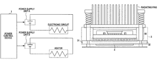
First, a hardware configuration and a power supply system of a server apparatus 0 serving as an electronic apparatus having an electronic circuit 3 mounted therein according to a first embodiment will be described. FIG. 1 is a diagram illustrating the hardware configuration of the server apparatus 0 according to the first embodiment, and FIG. 2 is a diagram illustrating the power supply system of the server apparatus 0 according to the first embodiment.
Referring to FIG. 1, the server apparatus 0 of this embodiment includes a power control device 1, DC-DC (Direct Current-Direct Current) converters 20, 21, the aforementioned electronic circuit 3 and a heater 4. The power control device 1 supplies electric power to the electronic circuit 3 and the heater 4 through the DC- DC converters 20 and 21, respectively. The power control device 1 includes a micro processing unit (MPU) 10 serving as an arithmetic processing device for controlling a supply of electric power to the electronic circuit 3 and the heater 4. The DC-DC converter 20 converts an input DC (Direct Current) voltage into a DC voltage of an electric current supplied to the electronic circuit 3, whereas the DC-DC converter 21 converts an input DC voltage into a DC voltage of an electric current supplied to the heater 4. The heater 4 serves to heat the electronic circuit 3 which will be described later.
The power supply system of the server apparatus 0 of this embodiment is divided into a power supply unit A which is a power source of the electronic circuit 3 and a power supply unit B which is a power source of the heater 4 as illustrated in FIG. 2, respectively. Therefore, electric power is supplied individually to the electronic circuit 3 and the heater 4 through independent power feeding systems. Here, it is assumed that the electronic circuit 3 produces heat equivalent to 35 W of power and reaches a temperature of 46 degrees Celsius under stable operating conditions and the amount of electric power supplied to the heater 4 is 9 W in this embodiment, for example. The amount of electric power supplied to the heater 4 is determined on the basis of the temperature of the electronic circuit 3 premeasured under stable operating conditions, the stable operating conditions designating a state in which the electronic circuit 3 in operation is at an average temperature.
Next, a configuration of the electronic circuit 3 is described. FIG. 3 is a diagram illustrating the electronic circuit 3 according to the first embodiment.
Referring to FIG. 3, the electronic circuit 3 of this embodiment includes a BGA-type semiconductor package 30 and a printed circuit board 31 which are joined together by solder bumps 32. The printed circuit board 31 is fitted with the aforementioned heater 4 and radiating fins are attached to an upper part of the semiconductor package 30. It is to be noted that the heater 4 may be mounted at any location as long as the heater 4 can heat the electronic circuit 3.
A functional configuration of the power control device 1 of the present embodiment is now described. FIG. 4 is a diagram illustrating the functional configuration of the power control device 1 according to the first embodiment.
Referring to FIG. 4, the power control device 1 includes a circuit power supply control block 11 (first power controller), a heater power supply control block 12 (second power controller) and a decision block 13. The circuit power supply control block 11 controls on/off operations of a power supply (circuit power supply) which supplies electric power to the electronic circuit 3, wherein the circuit power supply is controlled when starting up the server apparatus 0. The decision block 13 determines whether the circuit power supply control block 11 turns on or off the circuit power supply. The heater power supply control block 12 controls on/off operations of a power supply (heater power supply) which supplies electric power to the heater 4 according to a decision made by the decision block 13. The circuit power supply control block 11, the heater power supply control block 12 and the decision block 13 are implemented using the MPU 10.
A power supply control operation performed by the power control device 1 is described. FIG. 5 is a flowchart illustrating the power supply control operation performed by the power control device 1 according to the first embodiment.
First, the decision block 13 judges whether the circuit power supply is turned on by the circuit power supply control block 11, that is, whether electric power is supplied to the electronic circuit 3 (S101).
If the circuit power supply is on (Yes in S101), the heater power supply control block 12 turns off the heater power supply to cut off the supply of electric power to the heater 4 (S103) and, then, the decision block 13 judges again whether the circuit power supply is on (S101).
If, on the other hand, the circuit power supply is not on (No in S101), the heater power supply control block 12 turns on the heater power supply to supply electric power to the heater 4 (S102) and, then, the decision block 13 judges again whether the circuit power supply is on (S101).
The electronic circuit 3 is fitted with the heater 4 and electric power is individually supplied to the electronic circuit 3 and the heater 4 respectively through the independent power feeding systems as discussed above. This arrangement makes it possible to maintain the electronic circuit 3 at a constant temperature by turning on the heater power supply when the circuit power supply is off. As a result, it is possible to reduce plastic strain in the solder bumps 32.
A second embodiment differs from the foregoing first embodiment in that a sensor is added to the electronic circuit and the heater power supply is controlled on the basis of a temperature measured by the sensor. The structure and working of the second embodiment differing from the first embodiment are described below. It is to be noted that the following discussion deals with points differing from the first embodiment and part of the structure of the second embodiment shared commonly with the first embodiment is not described below.
First, a hardware configuration and a power supply system of a server apparatus 0 according to the second embodiment will be described. FIG. 6 is a diagram illustrating the hardware configuration of the server apparatus 0 according to the second embodiment, and FIG. 7 is a diagram illustrating the power supply system of the server apparatus 0 according to the second embodiment.
As illustrated in FIG. 6, the server apparatus 0 of this embodiment further includes a sensor 5 and a DC-DC converter 22. The DC-DC converter 22 converts an input DC voltage into a DC voltage of an electric current supplied to the sensor 5 which measures the temperature of the electronic circuit 3. Here, it is assumed that the electronic circuit 3 reaches a temperature of 50 degrees Celsius under stable operating conditions in this embodiment, for example.
The power supply system of the server apparatus 0 of this embodiment is divided into a power supply unit A which is a power source of the electronic circuit 3, a power supply unit B which is a power source of the heater 4 and a power supply unit C which is a power source of the sensor 5 as illustrated in FIG. 7, so that electric power is supplied individually to the electronic circuit 3, the heater 4 and the sensor 5 respectively through different power feeding systems. The power supply unit C supplies electric power to the sensor 5 as long as the server apparatus 0 is kept powered on.
The location of the sensor 5 is explained. FIG. 8 is a diagram illustrating the location of the sensor 5 relative to the electronic circuit 3 of the second embodiment.
The sensor 5 is mounted on a rear surface of the printed circuit board 31 as illustrated in FIG. 8, for example. However, the sensor 5 may be mounted at any location as long as the sensor 5 measures the temperature of the electronic circuit 3.
A functional configuration of the power control device 1 of the second embodiment is now described. FIG. 9 is a diagram illustrating the functional configuration of the power control device 1 according to the second embodiment.
As can be seen in FIG. 9, the power control device 1 of this embodiment differs from that of the first embodiment in that the power control device 1 further includes a temperature acquiring block 14 (which includes a power supply portion and a temperature data acquiring portion). The temperature acquiring block 14 continuously supplies electric power to the sensor 5 and acquires temperature of the electronic circuit 3 measured by the sensor 5. In this embodiment, the decision block 13 determines whether the temperature of the electronic circuit 3 acquired by the temperature acquiring block 14 is equal to or higher than a specific temperature. The specific temperature may be any temperature equal to or higher than the temperature of the electronic circuit 3 reaches under stable operating conditions. In this embodiment, the specific temperature is set at 50 degrees Celsius, for example. The temperature acquiring block 14 is implemented using the MPU 10.
Power supply control operation performed by the power control device 1 is described. FIG. 10 is a flowchart illustrating the power supply control operation performed by the power control device 1 according to the second embodiment.
First, the temperature acquiring block 14 acquires temperature of the electronic circuit 3 measured by the sensor 5 as illustrated in FIG. 10 (S201).
Next, the decision block 13 judges whether the temperature of the electronic circuit 3 acquired by the temperature acquiring block 14 is equal to or higher than 50 degrees Celsius (S202).
If the temperature of the electronic circuit 3 is equal to or higher than 50 degrees Celsius (Yes in S202), the heater power supply control block 12 turns off the heater power supply (S203) and, then, the temperature acquiring block 14 acquires again temperature of the electronic circuit 3 (S201).
If, on the other hand, the temperature of the electronic circuit 3 is lower than 50 degrees Celsius (No in S202), the heater power supply control block 12 turns on the heater power supply (S204) and, then, the temperature acquiring block 14 acquires again temperature of the electronic circuit 3 (S201).
The power control device 1 of this embodiment is configured to measure the temperature of the electronic circuit 3 by means of the sensor 5 and to control the heater 4 so that the temperature of the electronic circuit 3 becomes equal to or higher than the temperature reaches under stable operating conditions. This arrangement makes it possible to maintain the temperature of the electronic circuit 3 at a fixed level or higher regardless of whether the power supply of the electronic circuit 3 is on or off. As a result, it is possible to reduce plastic strain in the solder bumps 32.
While the heater 4 is mounted at a location where the heater 4 can heat the electronic circuit 3 in the foregoing first and second embodiments, the heater 4 is embedded in the printed circuit board 31 in the form of a heater circuit in a third embodiment. FIG. 11 is a diagram illustrating the heater 4 according to the third embodiment.
In this embodiment, the heater 4 is embedded in the printed circuit board 31 in the form of a heater circuit as illustrated in FIG. 11. The heater circuit is arranged to surround an area of the electronic circuit 3 where a semiconductor package is mounted. As the heater 4 is embedded in the printed circuit board 31 in this fashion, it is possible to heat the solder bumps 32 with high efficiency. The aforementioned arrangement of the third embodiment is similarly applicable to the foregoing first and second embodiments.
The aforementioned arrangement of the embodiment makes it possible to prevent the occurrence of plastic strain in solder bumps joining a semiconductor package to a printed circuit board with reduced power consumption.
As mentioned above, the present invention has been specifically described for better understanding of the embodiments thereof and the above description does not limit other aspects of the invention. Therefore, the present invention can be altered and modified in a variety of ways without departing from the gist and scope thereof.
All examples and conditional language recited herein are intended for pedagogical purposes to aid the reader in understanding the invention and the concepts contributed by the inventor to furthering the art, and are to be construed as being without limitation to such specifically recited examples and conditions, nor does the organization of such examples in the specification relate to a showing of the superiority and inferiority of the invention. Although the embodiments of the present inventions have been described in detail, it should be understood that the various changes, substitutions, and alterations could be made hereto without departing from the spirit and scope of the invention.

Claims (11)

1. An electronic apparatus comprising:
a printed circuit board;
a semiconductor device mounted on the printed circuit board by a plurality of solder bumps;
a heater that heats the printed circuit;
a sensor that measures a temperature of the semiconductor device;
a power supply unit that supplies electric power to the semiconductor device and the heater; and
a controller that controls, based on the temperature measured by the sensor, the power supply unit to supply electric power to the heater when the electric power is not supplied to the semiconductor device.
2. The electronic apparatus of claim 1, wherein the heater heats an area of the printed circuit where the plurality of solder bumps are arranged.
3. The electronic apparatus of claim 1, wherein the power supply unit includes a first power feeder for supplying electric power to the semiconductor device and a second power feeder for supplying electric power to the heater.
4. The electronic apparatus of claim 1, wherein the heater is embedded as a circuit on the printed circuit board.
5. A power control device for controlling a heater for heating an electric circuit including a semiconductor device operable under supply of an electric power mounted on a printed circuit board by a plurality of solder bumps, the power control device comprising:
a first power feeder that supplies electric power to the electric circuit;
a sensor that measures a temperature of the electric circuit;
a second power feeder that supplies electric power to the heater; and
a controller that determines, based on the temperature measured by the sensor, whether the electric power is supplied to the electric circuit and enables the second power feeder to supply the electric power to the heater when the electric power is not supplied to the electric circuit.
6. The power control device of claim 5, wherein the controller controls the second power feeder to supply electric power to the heater when the temperature is lower than a predetermined temperature.
7. The power control device of claim 6, wherein the predetermined temperature is higher than or equal to an average temperature of the electric circuit that is operating under supply of the electric power.
8. The power control device of claim 5, wherein the heater is embedded as a circuit on the printed circuit board.
9. A method of controlling a power control device for controlling a heater that heats an electric circuit including a semiconductor device operable under supply of an electric power mounted on a printed circuit board by a plurality of solder bumps, the method comprising:
controlling supply of electric power to the electric circuit by a first power feeder;
controlling supply of electric power to the heater by a second power feeder;
measuring a temperature of the electric circuit;
determining whether electric power is supplied to the electric circuit by a controller; and
enabling the second power feeder by the controller, based on the measured temperature, to supply electric power to the heater when electric power is not supplied to the electric circuit.
10. The method of claim 9, wherein the controller controls the second power feeder to supply electric power to the heater when the measured temperature is lower than a predetermined temperature.
11. The method of claim 10, wherein the predetermined temperature is higher than or equal to an average temperature of the electric circuit that is operating under supply of the electric power.
US12/748,554 2009-03-31 2010-03-29 Electronic apparatus, power control device for controlling a heater, and method of controlling power control device Expired - Fee Related US8309888B2 (en)

Applications Claiming Priority (2)

Application Number Priority Date Filing Date Title
JP2009-084044 2009-03-31
JP2009084044A JP2010238843A (en) 2009-03-31 2009-03-31 Power supply control device, electronic circuit mounting device, and power supply control method

Publications (2)

Publication Number Publication Date
US20100243634A1 US20100243634A1 (en) 2010-09-30
US8309888B2 true US8309888B2 (en) 2012-11-13

Family

ID=42782838

Family Applications (1)

Application Number Title Priority Date Filing Date
US12/748,554 Expired - Fee Related US8309888B2 (en) 2009-03-31 2010-03-29 Electronic apparatus, power control device for controlling a heater, and method of controlling power control device

Country Status (2)

Country Link
US (1) US8309888B2 (en)
JP (1) JP2010238843A (en)

Families Citing this family (5)

* Cited by examiner, † Cited by third party
Publication number Priority date Publication date Assignee Title
US20130342263A1 (en) * 2012-06-26 2013-12-26 Thorsten Meyer Heater for semiconductor device
EP3051794B1 (en) * 2013-09-27 2018-03-07 Hitachi Kokusai Electric Inc. Image pickup element unit and image pickup apparatus
JP2015111620A (en) * 2013-12-06 2015-06-18 シチズンホールディングス株式会社 Light emitting device and manufacturing method of the same
EP3104511B2 (en) 2015-06-09 2020-09-09 MARICI Holdings The Netherlands B.V. Electrical assembly
US10939537B1 (en) * 2019-12-19 2021-03-02 Honeywell International Inc. Printed circuit board assembly embedded thermal management system using thin-film thermoelectric coolers

Citations (1)

* Cited by examiner, † Cited by third party
Publication number Priority date Publication date Assignee Title
JPS6042795A (en) 1983-08-18 1985-03-07 セイコーインスツルメンツ株式会社 Electronic musical instrument

Family Cites Families (4)

* Cited by examiner, † Cited by third party
Publication number Priority date Publication date Assignee Title
JPS6042795U (en) * 1983-08-31 1985-03-26 富士通株式会社 Printed board
JP3224930B2 (en) * 1993-12-28 2001-11-05 株式会社東芝 Reproduction method of semiconductor device
JP2006135186A (en) * 2004-11-08 2006-05-25 Nec Corp Heating/heat insulating device of circuit
JP2008244288A (en) * 2007-03-28 2008-10-09 Fujitsu Ltd Semiconductor device provided with temperature control device and printed circuit board

Patent Citations (1)

* Cited by examiner, † Cited by third party
Publication number Priority date Publication date Assignee Title
JPS6042795A (en) 1983-08-18 1985-03-07 セイコーインスツルメンツ株式会社 Electronic musical instrument

Also Published As

Publication number Publication date
US20100243634A1 (en) 2010-09-30
JP2010238843A (en) 2010-10-21

Similar Documents

Publication Publication Date Title
US8309888B2 (en) Electronic apparatus, power control device for controlling a heater, and method of controlling power control device
US8706315B2 (en) Cooling controlling apparatus, electronic apparatus, and cooling controlling method
CN100527044C (en) Processor, processor system, temperature estimation device, information processing device, and temperature estimation method
US7185500B2 (en) Active cooling system for CPU
TWI734392B (en) Semiconductor memory device and memory system
JP6748625B2 (en) Current regulating equipment, system, method and computer readable recording medium for electronic device regulating electric power drawn from an external power source
US7904734B1 (en) Increasing mean time between failures for power supplies
CN105242715B (en) Temperature control equipment and equipment
US20070162160A1 (en) Fan speed control methods
US20140014313A1 (en) Multi-stage heat sink, cooling system with the same and method for controlling the same
WO2021129757A1 (en) Temperature control method and system and storage medium
JP2008218352A (en) Uninterruptible power supply unit, method for adjusting battery temperature used for same, and battery temperature adjusting program
CN103821747A (en) Fan control system, computer system and fan control method thereof
JP2022551526A (en) Systems and methods for providing thermal control in multi-stack fuel cell systems
CN102541239A (en) Network equipment and power consumption control method thereof
CN104520782A (en) Method and module for providing instructions for setting a supply voltage
WO2003083537A1 (en) Temperature controller and array waveguide lattice type optical wavelength multiplexer/demultiplexer
US20090085533A1 (en) Parallel supply current sharing using thermal feedback
JP6375826B2 (en) Supply power control device
JP5608889B2 (en) Electronic control unit
US20060271804A1 (en) Power consumption control for information handling system
EP4123891A1 (en) Power supply system and control in a dynamic load configuration
US20120026693A1 (en) Cooling Apparatus
JPH07302136A (en) Electronics
JP2016046424A (en) Semiconductor device

Legal Events

Date Code Title Description
AS Assignment

Owner name: FUJITSU LIMITED, JAPAN

Free format text: ASSIGNMENT OF ASSIGNORS INTEREST;ASSIGNORS:SO, TSUYOSHI;KUBO, HIDEO;REEL/FRAME:024172/0843

Effective date: 20100323

FEPP Fee payment procedure

Free format text: PAYOR NUMBER ASSIGNED (ORIGINAL EVENT CODE: ASPN); ENTITY STATUS OF PATENT OWNER: LARGE ENTITY

REMI Maintenance fee reminder mailed
LAPS Lapse for failure to pay maintenance fees
STCH Information on status: patent discontinuation

Free format text: PATENT EXPIRED DUE TO NONPAYMENT OF MAINTENANCE FEES UNDER 37 CFR 1.362

STCH Information on status: patent discontinuation

Free format text: PATENT EXPIRED DUE TO NONPAYMENT OF MAINTENANCE FEES UNDER 37 CFR 1.362

FP Lapsed due to failure to pay maintenance fee

Effective date: 20161113