US830366A - Whiffletree. - Google Patents
Whiffletree. Download PDFInfo
- Publication number
- US830366A US830366A US27641905A US1905276419A US830366A US 830366 A US830366 A US 830366A US 27641905 A US27641905 A US 27641905A US 1905276419 A US1905276419 A US 1905276419A US 830366 A US830366 A US 830366A
- Authority
- US
- United States
- Prior art keywords
- bar
- truss
- parts
- whiffletree
- bent
- Prior art date
- Legal status (The legal status is an assumption and is not a legal conclusion. Google has not performed a legal analysis and makes no representation as to the accuracy of the status listed.)
- Expired - Lifetime
Links
- 238000010276 construction Methods 0.000 description 3
- 230000008901 benefit Effects 0.000 description 2
- 230000008439 repair process Effects 0.000 description 2
- 238000006073 displacement reaction Methods 0.000 description 1
- 230000000284 resting effect Effects 0.000 description 1
Images
Classifications
-
- B—PERFORMING OPERATIONS; TRANSPORTING
- B62—LAND VEHICLES FOR TRAVELLING OTHERWISE THAN ON RAILS
- B62C—VEHICLES DRAWN BY ANIMALS
- B62C5/00—Draught assemblies
- B62C5/04—Swingletrees; Mountings thereof; Draught equalisers for a span of draught animals; Mountings for traces
Definitions
- This invention relates to improvements in whiffletrees, and is also applicable to neckyokes and similar articles, and especially to that kind of such articles in which a metallic ubular body or bar is provided with a truss-
- the chief object of this invention is to insure that the strain on the whiffletree shall be borne by the said parts to the best advantage, the extreme strain on the truss-bar not being applied until the more rigid body has been subjected to its greater proper share of stress.
- Figure 1 represents a plan view of a whiffletreee embodying my invention
- Figs. 2, 3, and 4 represent, respectively, detail views of the truss-bar before it is applied, one of the end caps, and the center bracket, the two parts of the latter being slightly separated
- Fig. 5 represents a detail longitudinal section of the end of the whiflietree
- Fig. 6 represents a modified form of part of the center bracket.
- A designates a whiffletree body or bar consisting of a piece of metallic pipe and having end caps C driven on its ends, which are provided with trace-hooks D and also used to hold in place the bent ends I) of the flat resilient truss-bar B.
- These ends are at first inclined outward beyond a position at right angles to the body of said truss-bar.
- the end caps 0 When applied to the body or bar A, they extend across the ends of the latter and are hammered thereon, the end caps 0 being then tightly driven on the ends of both parts and fastened to said body A, putting and holding said truss-bar under tension, since its bent ends are held in and its bent middle part is held out.
- a center bracket E is then applied to the middle of said body A and the outwardly-bent middle part of said truss-bar, such application being facilitated by the construction of said bracket in two or three parts or sections.
- the rear section E of said bracket is provided with forwardlyextending bifurcated ends 6, which straddle the truss-bar, and the middle of said section E being bent out to afford a good means of attachment of the whiffletree to the doubletree or other part or attachment of the ve hicle.
- the said forward-extending bifur cated ends as indicated in Fig. 4, also straddle and are riveted to the rearwardly-extend ing lugs e of straps or eyes 6, encircling the tubular whiflletree-bar A.
- a connecting-plate E as in Fig. 6.
- the latter is better suited to a doubletree and may have more than two straps or eyes a, if preferred.
- the truss-bar as thus applied and as shown in Fig. 1 has its outer parts I) parallel with and against the body A, to which they are secured by rivets Its middle part b is also parallel to said body, resting on the two arms of the U-shaped lower section E of the center bracket.
- the parts b intervening between said outer parts b and said middle part b are inclined downward, giving the bar B as a whole the familiar truss-form.
- the truss-bar gives the rigid whiflletree-body A the benefit of a resilient brace, but cannot be put under extreme tension till such body has borne its greater share of the strain.
- the center'bracket and end caps hold the bars A and B securely together and keep the latter in position, bracing it especially at the ends and in the middle; but by cutting away the rivets it is easy to separate the several parts of the whiffletree whenever repairs are needed. This whiflletree is easily made and put together at little cost, and there is no difficulty in replacing a damaged part.
- the said invention is applicable to neck-yokes, there being no substantial change, though the lower section E of the center bracket may be enlarged, or a ring and links or any other convenient means of rearward attachment may be substituted.
- a metallic whifiietree-body in combination with a metallic truss-bar under tension having its ends bent across the ends of said body, and caps fitting on the ends of said body over and inclosing the ends of said trussbar and serving to fasten the said body and truss-bar together substantially as set forth.
- a metallic bar for use in vehicles, whiffletrees and neck-yokes in combination with a truss-rod for bracing the same having integral parts which overlap the ends of said bars and closed caps which inclose these ends and overlapping parts and fasten the said bar and truss-rods together substantially as set forth.
- a metallic body for a whifiletree or similar article in combination with a continuous truss-bar bent out at the middle and having its ends bent over the ends of said body, means for holding the said ends in place and a center bracket in two or more parts, one part fitting on the said body and the other part or'parts against the under side of, the said brace-bar substantially as set forth.
- I 4 A metallic body or bar for a whifiietree or similar article, in combination with a continuous truss-bar having ends that fit on the ter ends and fasten the truss-bar ends in place and a center bracket which fits on the said body and holds the middle part of the said truss-bar, bracing the same substantially as set forth.
- a section of pipe constituting a tubular body for a whiffietree or similar article in combination with trace-hook-carrying caps fitting on the ends thereof, a continuous trussbar bent outward from said body in the middle but having its ends held by said caps and a center bracket consisting of two U-shaped sections, each having bifurcated ends, sai dsections being adapted to be fastened together, and holding between the bifurcations of their ends respectively the said body and the said truss-bar substantially as set forth.
Landscapes
- Engineering & Computer Science (AREA)
- Transportation (AREA)
- Mechanical Engineering (AREA)
- Devices Affording Protection Of Roads Or Walls For Sound Insulation (AREA)
Description
PATENTED SE-PT. 4, 1906.
J. NLRICHARDS. WHIFFLETREE.
APPLICATION FILED AUG.30. 190s.
inv'ir J e ra rns PATENT orrion.
WHIFFLETREE.
Specification of Letters Patent.
Patented Sept. 4, 1906.
Application filed August 30, 1905. Serial No. 276,419.
To all 1071 0717. it mar/71 concern:
Be it known that 1, JAMES N. RICHARDS, a citizen of the Dominion of Canada, residing at Chatham, in the county of Kent and Province of Ontario, Canada, have invented certain new and useful Improvements in l/Vhiffletrees; and I do hereby declare the following to be a full, clear, and exact description of the invention, such as will enable others skilled in the art to which it appertains to make and use the same.
This invention relates to improvements in whiffletrees, and is also applicable to neckyokes and similar articles, and especially to that kind of such articles in which a metallic ubular body or bar is provided with a truss- The chief object of this invention is to insure that the strain on the whiffletree shall be borne by the said parts to the best advantage, the extreme strain on the truss-bar not being applied until the more rigid body has been subjected to its greater proper share of stress.
I also aim to produce a simple, cheap, strong, durable, moderately-resilient article ofthe kind stated, easily taken apart for repairs, but securely held against accidental displacement of parts.
To these ends my said invention consists in the construction and combination of parts hereinafter more particularly set forth and claimed.
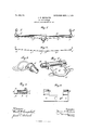
In the accompanying drawings, Figure 1 represents a plan view of a whiffletreee embodying my invention, and Figs. 2, 3, and 4 represent, respectively, detail views of the truss-bar before it is applied, one of the end caps, and the center bracket, the two parts of the latter being slightly separated. Fig. 5 represents a detail longitudinal section of the end of the whiflietree, and Fig. 6 represents a modified form of part of the center bracket.
A designates a whiffletree body or bar consisting of a piece of metallic pipe and having end caps C driven on its ends, which are provided with trace-hooks D and also used to hold in place the bent ends I) of the flat resilient truss-bar B. These ends, as shown in Fig. 4, are at first inclined outward beyond a position at right angles to the body of said truss-bar. When applied to the body or bar A, they extend across the ends of the latter and are hammered thereon, the end caps 0 being then tightly driven on the ends of both parts and fastened to said body A, putting and holding said truss-bar under tension, since its bent ends are held in and its bent middle part is held out. A center bracket E is then applied to the middle of said body A and the outwardly-bent middle part of said truss-bar, such application being facilitated by the construction of said bracket in two or three parts or sections. The rear section E of said bracket is provided with forwardlyextending bifurcated ends 6, which straddle the truss-bar, and the middle of said section E being bent out to afford a good means of attachment of the whiffletree to the doubletree or other part or attachment of the ve hicle. The said forward-extending bifur cated ends, as indicated in Fig. 4, also straddle and are riveted to the rearwardly-extend ing lugs e of straps or eyes 6, encircling the tubular whiflletree-bar A. These eyes or straps constitute the forward part of the center bracket, either alone or with the addition of a connecting-plate E as in Fig. 6. The latter is better suited to a doubletree and may have more than two straps or eyes a, if preferred. The truss-bar, as thus applied and as shown in Fig. 1 has its outer parts I) parallel with and against the body A, to which they are secured by rivets Its middle part b is also parallel to said body, resting on the two arms of the U-shaped lower section E of the center bracket. The parts b intervening between said outer parts b and said middle part b are inclined downward, giving the bar B as a whole the familiar truss-form. WVhen thus secured, the truss-bar gives the rigid whiflletree-body A the benefit of a resilient brace, but cannot be put under extreme tension till such body has borne its greater share of the strain. The center'bracket and end caps hold the bars A and B securely together and keep the latter in position, bracing it especially at the ends and in the middle; but by cutting away the rivets it is easy to separate the several parts of the whiffletree whenever repairs are needed. This whiflletree is easily made and put together at little cost, and there is no difficulty in replacing a damaged part.
As shown in Fig. 4, the said invention is applicable to neck-yokes, there being no substantial change, though the lower section E of the center bracket may be enlarged, or a ring and links or any other convenient means of rearward attachment may be substituted.
Of course my construction is as applicable to a doubletree or draft-equalizer as to an ordinary swingletree. (Shown in Fig. 1.)
Having thus described my invention, what I claim as new, and desire to secure by Letters Patent, is
1. A metallic whifiietree-body in combination with a metallic truss-bar under tension, having its ends bent across the ends of said body, and caps fitting on the ends of said body over and inclosing the ends of said trussbar and serving to fasten the said body and truss-bar together substantially as set forth.
2. A metallic bar for use in vehicles, whiffletrees and neck-yokes in combination with a truss-rod for bracing the same having integral parts which overlap the ends of said bars and closed caps which inclose these ends and overlapping parts and fasten the said bar and truss-rods together substantially as set forth.
3. A metallic body for a whifiletree or similar article, in combination with a continuous truss-bar bent out at the middle and having its ends bent over the ends of said body, means for holding the said ends in place and a center bracket in two or more parts, one part fitting on the said body and the other part or'parts against the under side of, the said brace-bar substantially as set forth.
I 4. A metallic body or bar for a whifiietree or similar article, in combination with a continuous truss-bar having ends that fit on the ter ends and fasten the truss-bar ends in place and a center bracket which fits on the said body and holds the middle part of the said truss-bar, bracing the same substantially as set forth.
5. A section of pipe constituting a tubular body for a whiffietree or similar article in combination with trace-hook-carrying caps fitting on the ends thereof, a continuous trussbar bent outward from said body in the middle but having its ends held by said caps and a center bracket consisting of two U-shaped sections, each having bifurcated ends, sai dsections being adapted to be fastened together, and holding between the bifurcations of their ends respectively the said body and the said truss-bar substantially as set forth.
In testimony whereof I have signed my name to this specification in the presence of two subscribing witnesses.
7 JAMES N. RICHARDS.
Witnesses:
ETHEL WIOKHAM, T. J. RUTLEY.
ends of said body, caps which fit on the lat-
Priority Applications (1)
| Application Number | Priority Date | Filing Date | Title |
|---|---|---|---|
| US27641905A US830366A (en) | 1905-08-30 | 1905-08-30 | Whiffletree. |
Applications Claiming Priority (1)
| Application Number | Priority Date | Filing Date | Title |
|---|---|---|---|
| US27641905A US830366A (en) | 1905-08-30 | 1905-08-30 | Whiffletree. |
Publications (1)
| Publication Number | Publication Date |
|---|---|
| US830366A true US830366A (en) | 1906-09-04 |
Family
ID=2898842
Family Applications (1)
| Application Number | Title | Priority Date | Filing Date |
|---|---|---|---|
| US27641905A Expired - Lifetime US830366A (en) | 1905-08-30 | 1905-08-30 | Whiffletree. |
Country Status (1)
| Country | Link |
|---|---|
| US (1) | US830366A (en) |
-
1905
- 1905-08-30 US US27641905A patent/US830366A/en not_active Expired - Lifetime
Similar Documents
| Publication | Publication Date | Title |
|---|---|---|
| US830366A (en) | Whiffletree. | |
| US360664A (en) | Whiffletree | |
| US742461A (en) | Draft-equalizer. | |
| US1241442A (en) | Draft-equalizer. | |
| US726611A (en) | Three-horse draft-equalizer. | |
| US497983A (en) | Clip for singletrees or whiffletrees | |
| US861917A (en) | Draft-equalizer. | |
| US698192A (en) | Whiffletree-clip. | |
| US425514A (en) | Draft-equalizer | |
| US751470A (en) | Draft-equalizer | |
| US604902A (en) | Draft-equalizer | |
| US636838A (en) | Draft-equalizer. | |
| US935434A (en) | Draft-equalizer. | |
| US474565A (en) | Whiffletree | |
| US937895A (en) | Draft-equalizer. | |
| US849364A (en) | Draft-equalizer. | |
| US245419A (en) | Whiffletree attachment | |
| US770718A (en) | Vehicle-tongue construction | |
| US175455A (en) | Improvement in draft-equalizers | |
| US755149A (en) | Draft-evener. | |
| US738405A (en) | Whiffletree-clip. | |
| US851566A (en) | Draft-equalizer. | |
| US218309A (en) | Improvement in whiffletrees | |
| US364487A (en) | John dailey | |
| US937975A (en) | Draft-equalizer. |