US8303540B2 - Pre-filled disposable syringe - Google Patents

Pre-filled disposable syringe Download PDF

Info

Publication number
US8303540B2
US8303540B2 US12/152,801 US15280108A US8303540B2 US 8303540 B2 US8303540 B2 US 8303540B2 US 15280108 A US15280108 A US 15280108A US 8303540 B2 US8303540 B2 US 8303540B2
Authority
US
United States
Prior art keywords
disposable syringe
disposed
bushing
grip
diameter portion
Prior art date
Legal status (The legal status is an assumption and is not a legal conclusion. Google has not performed a legal analysis and makes no representation as to the accuracy of the status listed.)
Active, expires
Application number
US12/152,801
Other versions
US20090124971A1 (en
Inventor
Ming-Jeng Shue
Phillip Shue
Deborah Huang
Current Assignee (The listed assignees may be inaccurate. Google has not performed a legal analysis and makes no representation or warranty as to the accuracy of the list.)
Individual
Original Assignee
Individual
Priority date (The priority date is an assumption and is not a legal conclusion. Google has not performed a legal analysis and makes no representation as to the accuracy of the date listed.)
Filing date
Publication date
Application filed by Individual filed Critical Individual
Publication of US20090124971A1 publication Critical patent/US20090124971A1/en
Application granted granted Critical
Publication of US8303540B2 publication Critical patent/US8303540B2/en
Active legal-status Critical Current
Adjusted expiration legal-status Critical

Links

Images

Classifications

    • AHUMAN NECESSITIES
    • A61MEDICAL OR VETERINARY SCIENCE; HYGIENE
    • A61MDEVICES FOR INTRODUCING MEDIA INTO, OR ONTO, THE BODY; DEVICES FOR TRANSDUCING BODY MEDIA OR FOR TAKING MEDIA FROM THE BODY; DEVICES FOR PRODUCING OR ENDING SLEEP OR STUPOR
    • A61M5/00Devices for bringing media into the body in a subcutaneous, intra-vascular or intramuscular way; Accessories therefor, e.g. filling or cleaning devices, arm-rests
    • A61M5/178Syringes
    • A61M5/31Details
    • A61M5/3129Syringe barrels
    • A61M5/3135Syringe barrels characterised by constructional features of the proximal end
    • AHUMAN NECESSITIES
    • A61MEDICAL OR VETERINARY SCIENCE; HYGIENE
    • A61MDEVICES FOR INTRODUCING MEDIA INTO, OR ONTO, THE BODY; DEVICES FOR TRANSDUCING BODY MEDIA OR FOR TAKING MEDIA FROM THE BODY; DEVICES FOR PRODUCING OR ENDING SLEEP OR STUPOR
    • A61M5/00Devices for bringing media into the body in a subcutaneous, intra-vascular or intramuscular way; Accessories therefor, e.g. filling or cleaning devices, arm-rests
    • A61M5/178Syringes
    • A61M5/31Details
    • A61M5/315Pistons; Piston-rods; Guiding, blocking or restricting the movement of the rod or piston; Appliances on the rod for facilitating dosing ; Dosing mechanisms
    • A61M5/31511Piston or piston-rod constructions, e.g. connection of piston with piston-rod
    • AHUMAN NECESSITIES
    • A61MEDICAL OR VETERINARY SCIENCE; HYGIENE
    • A61MDEVICES FOR INTRODUCING MEDIA INTO, OR ONTO, THE BODY; DEVICES FOR TRANSDUCING BODY MEDIA OR FOR TAKING MEDIA FROM THE BODY; DEVICES FOR PRODUCING OR ENDING SLEEP OR STUPOR
    • A61M5/00Devices for bringing media into the body in a subcutaneous, intra-vascular or intramuscular way; Accessories therefor, e.g. filling or cleaning devices, arm-rests
    • A61M5/178Syringes
    • A61M5/31Details
    • A61M5/32Needles; Details of needles pertaining to their connection with syringe or hub; Accessories for bringing the needle into, or holding the needle on, the body; Devices for protection of needles
    • A61M5/3205Apparatus for removing or disposing of used needles or syringes, e.g. containers; Means for protection against accidental injuries from used needles
    • A61M5/321Means for protection against accidental injuries by used needles
    • A61M5/322Retractable needles, i.e. disconnected from and withdrawn into the syringe barrel by the piston
    • A61M5/3234Fully automatic needle retraction, i.e. in which triggering of the needle does not require a deliberate action by the user
    • AHUMAN NECESSITIES
    • A61MEDICAL OR VETERINARY SCIENCE; HYGIENE
    • A61MDEVICES FOR INTRODUCING MEDIA INTO, OR ONTO, THE BODY; DEVICES FOR TRANSDUCING BODY MEDIA OR FOR TAKING MEDIA FROM THE BODY; DEVICES FOR PRODUCING OR ENDING SLEEP OR STUPOR
    • A61M5/00Devices for bringing media into the body in a subcutaneous, intra-vascular or intramuscular way; Accessories therefor, e.g. filling or cleaning devices, arm-rests
    • A61M5/50Devices for bringing media into the body in a subcutaneous, intra-vascular or intramuscular way; Accessories therefor, e.g. filling or cleaning devices, arm-rests having means for preventing re-use, or for indicating if defective, used, tampered with or unsterile
    • A61M5/5066Means for preventing re-use by disconnection of piston and piston-rod
    • AHUMAN NECESSITIES
    • A61MEDICAL OR VETERINARY SCIENCE; HYGIENE
    • A61MDEVICES FOR INTRODUCING MEDIA INTO, OR ONTO, THE BODY; DEVICES FOR TRANSDUCING BODY MEDIA OR FOR TAKING MEDIA FROM THE BODY; DEVICES FOR PRODUCING OR ENDING SLEEP OR STUPOR
    • A61M5/00Devices for bringing media into the body in a subcutaneous, intra-vascular or intramuscular way; Accessories therefor, e.g. filling or cleaning devices, arm-rests
    • A61M5/178Syringes
    • A61M5/31Details
    • A61M2005/3117Means preventing contamination of the medicament compartment of a syringe
    • A61M2005/3118Means preventing contamination of the medicament compartment of a syringe via the distal end of a syringe, i.e. syringe end for mounting a needle cannula
    • A61M2005/312Means preventing contamination of the medicament compartment of a syringe via the distal end of a syringe, i.e. syringe end for mounting a needle cannula comprising sealing means, e.g. severable caps, to be removed prior to injection by, e.g. tearing or twisting
    • AHUMAN NECESSITIES
    • A61MEDICAL OR VETERINARY SCIENCE; HYGIENE
    • A61MDEVICES FOR INTRODUCING MEDIA INTO, OR ONTO, THE BODY; DEVICES FOR TRANSDUCING BODY MEDIA OR FOR TAKING MEDIA FROM THE BODY; DEVICES FOR PRODUCING OR ENDING SLEEP OR STUPOR
    • A61M5/00Devices for bringing media into the body in a subcutaneous, intra-vascular or intramuscular way; Accessories therefor, e.g. filling or cleaning devices, arm-rests
    • A61M5/178Syringes
    • A61M5/31Details
    • A61M2005/3117Means preventing contamination of the medicament compartment of a syringe
    • A61M2005/3121Means preventing contamination of the medicament compartment of a syringe via the proximal end of a syringe, i.e. syringe end opposite to needle cannula mounting end
    • AHUMAN NECESSITIES
    • A61MEDICAL OR VETERINARY SCIENCE; HYGIENE
    • A61MDEVICES FOR INTRODUCING MEDIA INTO, OR ONTO, THE BODY; DEVICES FOR TRANSDUCING BODY MEDIA OR FOR TAKING MEDIA FROM THE BODY; DEVICES FOR PRODUCING OR ENDING SLEEP OR STUPOR
    • A61M5/00Devices for bringing media into the body in a subcutaneous, intra-vascular or intramuscular way; Accessories therefor, e.g. filling or cleaning devices, arm-rests
    • A61M5/178Syringes
    • A61M5/31Details
    • A61M5/32Needles; Details of needles pertaining to their connection with syringe or hub; Accessories for bringing the needle into, or holding the needle on, the body; Devices for protection of needles
    • A61M5/3205Apparatus for removing or disposing of used needles or syringes, e.g. containers; Means for protection against accidental injuries from used needles
    • A61M5/321Means for protection against accidental injuries by used needles
    • A61M5/322Retractable needles, i.e. disconnected from and withdrawn into the syringe barrel by the piston
    • A61M5/3221Constructional features thereof, e.g. to improve manipulation or functioning
    • A61M2005/323Connection between plunger distal end and needle hub proximal end, e.g. stud protruding from the plunger
    • AHUMAN NECESSITIES
    • A61MEDICAL OR VETERINARY SCIENCE; HYGIENE
    • A61MDEVICES FOR INTRODUCING MEDIA INTO, OR ONTO, THE BODY; DEVICES FOR TRANSDUCING BODY MEDIA OR FOR TAKING MEDIA FROM THE BODY; DEVICES FOR PRODUCING OR ENDING SLEEP OR STUPOR
    • A61M5/00Devices for bringing media into the body in a subcutaneous, intra-vascular or intramuscular way; Accessories therefor, e.g. filling or cleaning devices, arm-rests
    • A61M5/178Syringes
    • A61M5/31Details
    • A61M5/32Needles; Details of needles pertaining to their connection with syringe or hub; Accessories for bringing the needle into, or holding the needle on, the body; Devices for protection of needles
    • A61M5/3205Apparatus for removing or disposing of used needles or syringes, e.g. containers; Means for protection against accidental injuries from used needles
    • A61M5/321Means for protection against accidental injuries by used needles
    • A61M5/322Retractable needles, i.e. disconnected from and withdrawn into the syringe barrel by the piston
    • A61M5/3221Constructional features thereof, e.g. to improve manipulation or functioning
    • A61M2005/3231Proximal end of needle captured or embedded inside piston head, e.g. by friction or hooks
    • AHUMAN NECESSITIES
    • A61MEDICAL OR VETERINARY SCIENCE; HYGIENE
    • A61MDEVICES FOR INTRODUCING MEDIA INTO, OR ONTO, THE BODY; DEVICES FOR TRANSDUCING BODY MEDIA OR FOR TAKING MEDIA FROM THE BODY; DEVICES FOR PRODUCING OR ENDING SLEEP OR STUPOR
    • A61M5/00Devices for bringing media into the body in a subcutaneous, intra-vascular or intramuscular way; Accessories therefor, e.g. filling or cleaning devices, arm-rests
    • A61M5/178Syringes
    • A61M5/31Details
    • A61M5/32Needles; Details of needles pertaining to their connection with syringe or hub; Accessories for bringing the needle into, or holding the needle on, the body; Devices for protection of needles
    • A61M5/3205Apparatus for removing or disposing of used needles or syringes, e.g. containers; Means for protection against accidental injuries from used needles
    • A61M5/321Means for protection against accidental injuries by used needles
    • A61M5/322Retractable needles, i.e. disconnected from and withdrawn into the syringe barrel by the piston
    • A61M5/3234Fully automatic needle retraction, i.e. in which triggering of the needle does not require a deliberate action by the user
    • A61M2005/3239Fully automatic needle retraction, i.e. in which triggering of the needle does not require a deliberate action by the user triggered by dislodgement of outer part anchoring the needle portion to the inside of the syringe barrel wall, e.g. a ring-shaped portion
    • AHUMAN NECESSITIES
    • A61MEDICAL OR VETERINARY SCIENCE; HYGIENE
    • A61MDEVICES FOR INTRODUCING MEDIA INTO, OR ONTO, THE BODY; DEVICES FOR TRANSDUCING BODY MEDIA OR FOR TAKING MEDIA FROM THE BODY; DEVICES FOR PRODUCING OR ENDING SLEEP OR STUPOR
    • A61M5/00Devices for bringing media into the body in a subcutaneous, intra-vascular or intramuscular way; Accessories therefor, e.g. filling or cleaning devices, arm-rests
    • A61M5/178Syringes
    • A61M5/31Details
    • A61M5/32Needles; Details of needles pertaining to their connection with syringe or hub; Accessories for bringing the needle into, or holding the needle on, the body; Devices for protection of needles
    • A61M5/3205Apparatus for removing or disposing of used needles or syringes, e.g. containers; Means for protection against accidental injuries from used needles
    • A61M5/321Means for protection against accidental injuries by used needles
    • A61M5/322Retractable needles, i.e. disconnected from and withdrawn into the syringe barrel by the piston
    • A61M5/3234Fully automatic needle retraction, i.e. in which triggering of the needle does not require a deliberate action by the user
    • A61M2005/3241Needle retraction energy is accumulated inside of a hollow plunger rod
    • A61M2005/3242Needle retraction by vacuum
    • AHUMAN NECESSITIES
    • A61MEDICAL OR VETERINARY SCIENCE; HYGIENE
    • A61MDEVICES FOR INTRODUCING MEDIA INTO, OR ONTO, THE BODY; DEVICES FOR TRANSDUCING BODY MEDIA OR FOR TAKING MEDIA FROM THE BODY; DEVICES FOR PRODUCING OR ENDING SLEEP OR STUPOR
    • A61M5/00Devices for bringing media into the body in a subcutaneous, intra-vascular or intramuscular way; Accessories therefor, e.g. filling or cleaning devices, arm-rests
    • A61M5/002Packages specially adapted therefor, e.g. for syringes or needles, kits for diabetics
    • AHUMAN NECESSITIES
    • A61MEDICAL OR VETERINARY SCIENCE; HYGIENE
    • A61MDEVICES FOR INTRODUCING MEDIA INTO, OR ONTO, THE BODY; DEVICES FOR TRANSDUCING BODY MEDIA OR FOR TAKING MEDIA FROM THE BODY; DEVICES FOR PRODUCING OR ENDING SLEEP OR STUPOR
    • A61M5/00Devices for bringing media into the body in a subcutaneous, intra-vascular or intramuscular way; Accessories therefor, e.g. filling or cleaning devices, arm-rests
    • A61M5/178Syringes
    • A61M5/31Details
    • A61M5/3129Syringe barrels
    • A61M5/3134Syringe barrels characterised by constructional features of the distal end, i.e. end closest to the tip of the needle cannula
    • AHUMAN NECESSITIES
    • A61MEDICAL OR VETERINARY SCIENCE; HYGIENE
    • A61MDEVICES FOR INTRODUCING MEDIA INTO, OR ONTO, THE BODY; DEVICES FOR TRANSDUCING BODY MEDIA OR FOR TAKING MEDIA FROM THE BODY; DEVICES FOR PRODUCING OR ENDING SLEEP OR STUPOR
    • A61M5/00Devices for bringing media into the body in a subcutaneous, intra-vascular or intramuscular way; Accessories therefor, e.g. filling or cleaning devices, arm-rests
    • A61M5/178Syringes
    • A61M5/31Details
    • A61M5/3129Syringe barrels
    • A61M5/3137Specially designed finger grip means, e.g. for easy manipulation of the syringe rod
    • AHUMAN NECESSITIES
    • A61MEDICAL OR VETERINARY SCIENCE; HYGIENE
    • A61MDEVICES FOR INTRODUCING MEDIA INTO, OR ONTO, THE BODY; DEVICES FOR TRANSDUCING BODY MEDIA OR FOR TAKING MEDIA FROM THE BODY; DEVICES FOR PRODUCING OR ENDING SLEEP OR STUPOR
    • A61M5/00Devices for bringing media into the body in a subcutaneous, intra-vascular or intramuscular way; Accessories therefor, e.g. filling or cleaning devices, arm-rests
    • A61M5/178Syringes
    • A61M5/31Details
    • A61M5/32Needles; Details of needles pertaining to their connection with syringe or hub; Accessories for bringing the needle into, or holding the needle on, the body; Devices for protection of needles
    • A61M5/3202Devices for protection of the needle before use, e.g. caps
    • AHUMAN NECESSITIES
    • A61MEDICAL OR VETERINARY SCIENCE; HYGIENE
    • A61MDEVICES FOR INTRODUCING MEDIA INTO, OR ONTO, THE BODY; DEVICES FOR TRANSDUCING BODY MEDIA OR FOR TAKING MEDIA FROM THE BODY; DEVICES FOR PRODUCING OR ENDING SLEEP OR STUPOR
    • A61M5/00Devices for bringing media into the body in a subcutaneous, intra-vascular or intramuscular way; Accessories therefor, e.g. filling or cleaning devices, arm-rests
    • A61M5/178Syringes
    • A61M5/31Details
    • A61M5/32Needles; Details of needles pertaining to their connection with syringe or hub; Accessories for bringing the needle into, or holding the needle on, the body; Devices for protection of needles
    • A61M5/329Needles; Details of needles pertaining to their connection with syringe or hub; Accessories for bringing the needle into, or holding the needle on, the body; Devices for protection of needles characterised by features of the needle shaft
    • A61M5/3291Shafts with additional lateral openings
    • AHUMAN NECESSITIES
    • A61MEDICAL OR VETERINARY SCIENCE; HYGIENE
    • A61MDEVICES FOR INTRODUCING MEDIA INTO, OR ONTO, THE BODY; DEVICES FOR TRANSDUCING BODY MEDIA OR FOR TAKING MEDIA FROM THE BODY; DEVICES FOR PRODUCING OR ENDING SLEEP OR STUPOR
    • A61M5/00Devices for bringing media into the body in a subcutaneous, intra-vascular or intramuscular way; Accessories therefor, e.g. filling or cleaning devices, arm-rests
    • A61M5/178Syringes
    • A61M5/31Details
    • A61M5/32Needles; Details of needles pertaining to their connection with syringe or hub; Accessories for bringing the needle into, or holding the needle on, the body; Devices for protection of needles
    • A61M5/34Constructions for connecting the needle, e.g. to syringe nozzle or needle hub
    • A61M5/344Constructions for connecting the needle, e.g. to syringe nozzle or needle hub using additional parts, e.g. clamping rings or collets

Landscapes

  • Health & Medical Sciences (AREA)
  • Engineering & Computer Science (AREA)
  • Hematology (AREA)
  • Anesthesiology (AREA)
  • Biomedical Technology (AREA)
  • Heart & Thoracic Surgery (AREA)
  • Vascular Medicine (AREA)
  • Life Sciences & Earth Sciences (AREA)
  • Animal Behavior & Ethology (AREA)
  • General Health & Medical Sciences (AREA)
  • Public Health (AREA)
  • Veterinary Medicine (AREA)
  • Environmental & Geological Engineering (AREA)
  • Infusion, Injection, And Reservoir Apparatuses (AREA)

Abstract

A disposable syringe includes a barrel with a bushing unit disposed on an inner surrounding surface thereof, a tubular grip unit in fluid-tight engagement with the bushing unit for holding a needle seat, a tubular plunger having a seal ring that is slidable on and in fluid-tight frictional engagement with the bushing unit so as to cooperate with the grip unit to define a medicament chamber, and a shield plug member in fluid-tight engagement with the grip unit and having a duct that communicates a needle cannula with the medicament chamber, thereby ensuring fluid-tightness of the medicament chamber.

Description

CROSS-REFERENCE TO RELATED APPLICATION
This application claims priority of Taiwanese publication No. 096142665, filed on Nov. 12, 2007.
BACKGROUND OF THE INVENTION
1. Field of the Invention
This invention relates to a disposable syringe, more particularly to a pre-filled disposable syringe for facilitating injection and needle retraction operations with one hand.
2. Description of the Related Art
In U.S. Pat. No. 6,221,055 B1 for a retractable dental syringe, there is disclosed a pre-filled syringe, which includes a barrel, a carpule and plunger assembly that is filled with medication and that is inserted into the barrel from a rear opened end of the barrel and that is communicated with a needle by the carpule is punctured by a rear tip end of the needle, and a push ring for holding the needle in the barrel. At the end of an injection, the plunger is further pressed to move the carpule forwardly so that the push ring is removed to permit retraction of the needle. However, the carpule cannot be accommodated in the barrel in advance, and the carpule and the barrel have to be packed separately for subsequent assembly in use, thereby resulting in increased operation time. In addition, such a syringe structure makes the manufacture of the syringe complicated.
Therefore, in U.S. patent application Ser. No. 11/601,526, the applicants disclosed a disposable syringe with a built-in carpule, which includes a carpule that can be pre-assembled in a barrel so that clinical injection operation by health care workers is simplified and is convenient to conduct. Moreover, after injection, the syringe can be conveniently rendered unreusable after injection, and injection and needle retraction can be conducted smoothly in a single operation.
It is desirable to improve the aforesaid syringe to ensure air- and water-tightness of a medicament chamber so as to eliminate risk of degradation of a medicament contained therein, and to simplify the construction of the syringe.
SUMMARY OF THE INVENTION
The object of the present invention is to provide a disposable syringe which can maintain air- and water-tightness of a medicament chamber to eliminate risk of degradation of a medicament contained therein, and which has a simple construction to achieve cost savings.
According to this invention, the disposable syringe includes a barrel, a bushing unit, a needle cannula, a tubular grip unit, a tubular needle seat, a shield plug member, and a tubular plunger.
The barrel has a surrounding barrel wall defining a passage therein. The passage has rearward and forward openings. The surrounding barrel wall includes a larger-diameter portion and a smaller-diameter portion, and a shoulder abutment disposed on the smaller-diameter portion and confronting rearwardly.
The bushing unit is disposed on the larger-diameter portion, and includes front and rear bushing members that extend towards each other to terminate at front and rear retaining segments, respectively.
The needle cannula has a fixed segment extending in the passage to terminate at a communicating end, and a tip end extending forwardly of the forward opening.
The tubular grip unit includes front and rear grip members which respectively have front and rear outer surrounding retained surfaces that, in a position of use, are respectively in fluid-tight engagement with the front and rear retaining segments, by virtue of first and second frictional forces, respectively, and which respectively further have front and rear inner surrounding grip surfaces that respectively define front and rear bores.
The tubular needle seat includes a front hub portion which is disposed to fix the needle cannula therein and which has a front end wall that confronts the shoulder abutment, and a rear gripped portion extending rearwardly to terminate at an embedded end. The rear gripped portion is inserted into the front bore, and is in frictional engagement with the front inner surrounding grip surface.
The shield plug member is made from a material different from that of the tubular needle seat, and is inserted into the rear bore. The shield plug member includes a plug body and an anchored end. The plug body extends forwardly to terminate at a dock end that admits entry of the communicating end of the needle cannula, and is configured to stuff the rear bore so as to be in fluid-tight engagement with the rear inner surrounding grip surface. The anchored end has a duct configured to permit fluid communication between the anchored end and the communicating end.
The tubular plunger is movable along the passage in the bushing unit, and includes a plunger body, a seal ring, and a coupling member. The plunger body has front and rear opened end walls, and an intermediate surrounding wall defining an accommodation chamber. The seal ring is sleeved retainingly on the front opened end wall, and is slidable on and in fluid-tight frictional engagement with the rear bushing member so as to cooperate with the rear grip member to define, in the passage, a medicament chamber that is communicated with the duct. The coupling member has a retained portion disposed in the accommodation chamber to be in frictional engagement with the intermediate surrounding wall by virtue of a third frictional force, and an anchoring portion that is engageable with the anchored end when the coupling member is moved forwardly. When the front and rear grip members are pushed forward by virtue of forward movement of the plunger against the first and second frictional forces, the anchoring portion is brought to mate with the anchored end, which remains unmoved and stays in place due to abutment of the front hub portion against the shoulder abutment. Once the plunger is moved further forward to cause movement of the plunger body relative to the coupling member against the third frictional force, the retained portion is released from the intermediate surrounding wall to thereby permit movement of the anchored end with the anchoring portion to a retracted position, where the anchoring portion is disposed closer to the rear opened end wall and where the needle seat, the shield plug member and the needle cannula are received in the accommodation chamber.
BRIEF DESCRIPTION OF THE DRAWINGS
Other features and advantages of the present invention will become apparent in the following detailed description of the preferred embodiments of the invention, with reference to the accompanying drawings, in which:
FIG. 1 is an exploded sectional view of the first preferred embodiment of a disposable syringe according to this invention;
FIG. 2 is a sectional view of the first preferred embodiment in assembly;
FIG. 3 is a rear view of a pair of finger flanges of the first preferred embodiment;
FIG. 4 is a sectional view of the first preferred embodiment in a state of use;
FIG. 5 is a fragmentary sectional view of the first preferred embodiment in a state after a medicament injection is completed;
FIG. 6 is a sectional view of the first preferred embodiment when a needle seat is released from a grip unit;
FIG. 7 is a sectional view of the first preferred embodiment in a retracted state;
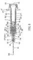
FIG. 8 is a sectional view of the second preferred embodiment of a disposable syringe according to this invention;
FIG. 9 is a fragmentary sectional view of the second preferred embodiment in a state of use;
FIG. 10 is an exploded sectional view of the third preferred embodiment of a disposable syringe according to this invention;
FIGS. 11 and 12 are sectional views of the third preferred embodiment in a state of use and in a retracted state, respectively;
FIG. 13 is a sectional view of the fourth preferred embodiment of a disposable syringe according to this invention; and
FIGS. 14 and 15 are sectional views of the fifth preferred embodiment of a disposable syringe according to this invention in a pre-used state and a state of use, respectively.
DETAILED DESCRIPTION OF THE PREFERRED EMBODIMENTS
Before the present invention is described in greater detail, it should be noted that same reference numerals have been used to denote like elements throughout the specification.
Referring to FIGS. 1 to 3, the first preferred embodiment of a disposable syringe according to the present invention is shown to comprise a barrel 1, a bushing unit 10, a needle cannula 24, a tubular grip unit 4, a tubular needle seat 23, a shield plug member 5, a tubular plunger 3, a coil spring 13, and front and rear protectors 14,15.
The barrel 1 has a surrounding barrel wall 12 which surrounds an axis in an axial direction, and which defines a passage 11 therein. The passage 11 has rearward and forward openings 121,122 which are disposed opposite to each other in the axial direction. The surrounding barrel wall 12 includes a larger-diameter portion 123 and a smaller-diameter portion 124 which are disposed proximate to the rearward and forward openings 121,122, respectively. The smaller-diameter portion 124 has a first shoulder abutment 127 confronting rearwardly A second shoulder abutment 125 is formed between the smaller-diameter portion 124 and the larger-diameter portion 123, and confronts forwardly. The larger-diameter portion 123 has a third shoulder abutment 128 which is disposed adjacent to the rearward opening 121 and which confronts rearwardly. A pair of lugs 17 extend radially and outwardly from the larger-diameter portion 123 adjacent to the rearward opening 121 for gripping by user's fingers, and has anchor holes 171 for anchoring a marked tab, as shown in FIG. 3, which indicates the name and amount of a medicament, the name of a patient, etc.
The bushing unit 10 is disposed on the larger-diameter portion 123, and includes front and rear bushing members 101,102 that are proximate to and distal from the first shoulder abutment 127, respectively, and that extend towards each other to terminate at front and rear retaining segments 103,104, respectively.
In this embodiment, the front and rear bushing members 101, 102 are integrally formed with each other to constitute the bushing unit 10. The bushing unit 10 is integrally formed with the larger-diameter portion 123, and is made from a glass material, or a thermoplastic macromolecular material with chemical resistance, such as a cyclic olefin polymer or the like.
The needle cannula 24 extends along the axis and has a fixed segment 241 that extends in the passage 11 to terminate at a communicating end 243, and a tip end 242 extending forwardly of the forward opening 122. In addition, a tubular holding member 18 is inserted into the passage 11 from the forward opening 122 of the barrel 1 to be fitted to the smaller-diameter portion 124, and is configured to hold the needle cannula 24 in a position of use. An air-tight sleeve 25 is removably sleeved on the smaller-diameter portion 124 to shield the needle cannula 24, and has an elastomeric front end 252 such that the tip end 242 of the needle cannula 24 is trapped in the elastomeric front end 252.
The tubular grip unit 4 includes front and rear grip members 41,42 which are opposite to each other in the axial direction, which respectively have front and rear outer surrounding retained surfaces 411,421 that, in the position of use, are respectively in air and water-tight engagement with the front and rear retaining segments 103,104, by virtue of first and second frictional forces, respectively, and which respectively have front and rear inner surrounding grip surfaces 412,422 that respectively extend along the axis to define front and rear bores 413,423, respectively. In this embodiment, the front and rear grip members 41,42 are integrally formed with each other. Specifically, the barrel 1 is made from a thermoplastic material, and the front and rear retaining segments 103,104 are formed with a protruding ring such that the front and rear outer surrounding retained surfaces 411,421 of the tubular grip unit 4 are retainingly secured to the protruding ring. Alternatively, the barrel 1 may be made from a glass material so as to have a smooth inner wall surface, and the tubular grip unit 4 is press-fitted to the front and rear retaining segments 103,104, which are not formed with the protruding ring (as shown in FIGS. 8 to 10).
The tubular needle seat 23 includes a front hub portion 231 which is disposed to fix the needle cannula 24 therein and which has a front end wall 2311 that confronts the first shoulder abutment 127, and a rear gripped portion 232 extending from the front hub portion 231 in the axial direction to terminate at an embedded end 234. The rear gripped portion 232 is inserted into the front bore 413, and is in frictional engagement with the front inner surrounding grip surface 412.
The shield plug member 5 is made from a material different from that of the tubular needle seat 23, and is inserted into the rear bore 423. The shield plug member 5 includes a plug body 51 and an anchored end 52. The plug body 51 extends forwardly to terminate at a dock end 511. In this embodiment, the embedded end 234 of the needle seat 23 is disposed to surround the dock end 511 in the rear bore 423 such that the dock end 511 admits entry of the communicating end 243 of the needle cannula 24. The dock end 511 is configured to stuff the rear bore 423 such that the plug body 51 is in fluid-tight engagement with the rear inner surrounding grip surface 422. The anchored end 52 extends rearwardly from the plug body 51, and has a duct 521 configured to extend in the axial direction to permit fluid communication between the anchored end 52 and the communicating end 243 in the position of use. Specifically, the anchored end 52 is in the form of a plug which is disposed rearwardly and outwardly of the rear grip member 42. In addition, the anchored end 52 is provided with a radial inlet 55 which extends radially to be communicated with the communicating end 243 of the needle cannula 24, and which is disposed adjacent to the rear grip member 42.
The tubular plunger 3 is disposed to be movable along the passage 11 in the bushing unit 10, and includes a plunger body 31, a seal ring 33, and a coupling member 32. The plunger body 31 has front and rear opened end walls 313,314 which are disposed opposite to each other along the axis. The rear opened end wall 314 extends outwardly of the rearward opening 121 so as to be manually operable. The plunger body 31 further has an intermediate surrounding wall 312 which is interposed between the front and rear opened end walls 313,314 and which defines an accommodation chamber 311. An end cap 34 is disposed to cover the rear opened end wall 314. Preferably, the accommodation chamber 311 may contain fluid at a reduced pressure.
The seal ring 33 is made from a deformable material, is sleeved retainingly on the front opened end wall 313, and is slidable on and in fluid-tight frictional engagement with the rear bushing member 102 so as to cooperate with the rear grip member 42 to define in the passage 11 a medicament chamber 30 that is communicated with the duct 521.
The coupling member 32 has a retained portion 322 that extends along the axis and that is disposed in the accommodation chamber 311 to be in frictional engagement with the intermediate surrounding wall 312 by virtue of a third frictional force, and an anchoring portion 321 extending forwardly from the retained portion 322. Specifically, the anchoring portion 321 is inform of a socket so as to mate with the plug-like anchored end 52 when the coupling member 32 is moved forwardly.
Preferably, as shown in FIG. 5, the smaller-diameter portion 124 has a friction diminishing area 129 which is disposed between the first shoulder abutment 127 and the front hub portion 231 of the needle seat 23.
The coil spring 13 is disposed within the smaller-diameter portion 124 to surround the needle cannula 24, and has two spring ends 131,132 which respectively abut against the smaller-diameter portion 124 and the front end wall 2311 so as to bias the needle seat 23, together with the shield plug member 5 to move rearwardly.
The front protector 14 is detachably sleeved on the smaller-diameter portion 124, and abuts against the second shoulder abutment 125 for shielding the air-tight sleeve 25. The rear protector 15 is detachably sleeved on the larger-diameter portion 123, and abuts against the third shoulder abutment 128 for shielding the plunger 3. Front and rear sealing strips 16 are disposed to peelably adhere the front protector 14 to the second shoulder abutment 125, and to peelably adhere the rear protector 15 to the larger-diameter portion 123, respectively. Preferably, the elastomeric front end 252 of the air-tight sleeve 25 is threadedly engaged with the front protector 14.
It is noted that the barrel 1, the coupling member 32, the seal ring 33, the tubular grip unit 4, and the shield plug member 5 are made from a chemically resistant material, and cooperatively define the medicament chamber 30 so that the medicament chamber 30 has good air-tightness and water-tightness, and can ensure the quality of the medicament contained therein.
Referring to FIGS. 2, 4 and 5, during an injection stroke, the front and rear protectors 14,15 are removed first to expose the needle cannula 24 and the plunger body 31. The operator then holds the lugs 17 with his/her index and middle fingers and presses the plunger body 31 forwardly with his/her thumb such that the coupling member 32 and the seal ring 33 are moved forwardly along the rear bushing member 102 to expel air from the barrel 1 and accurately adjust a dosage of medicament within the barrel 1. The medicament is in turn introduced into the patient through the duct 521, the radial inlet 55 and the needle cannula 24. Subsequently, a pushing force is applied to the plunger body 31 to bring the seal ring 33 into abutment against the grip unit 4, thereby completing the injection stroke, as shown in FIG. 5. At this time, the anchoring portion 321 is fittingly engaged with the anchored end 52 for preventing dripping of the medicament.
It is noted that, during the injection operation, the radial inlet 55 can remain open when the socket-like anchoring portion 321 is brought to substantially engage the plug-like anchored end 52 to interrupt axial communication between the duct 521 and the medicament chamber 30 so as to dispense the entire amount of medicament in the medicament chamber 30.
With reference to FIGS. 6 and 7, a pushing force is further applied to the plunger body 31 to push the grip unit 4 forward against the first and second frictional forces (i.e., the frictional engagement between the grip unit 4 and the bushing unit 10) such that the front hub portion 231 of the needle seat 23 moves past the friction diminishing area 129 to abut against the first shoulder abutment 127, thereby facilitating a triggering action for retraction of the needle cannula 24 (to be described in detail hereinafter). Hence, the movement of the front hub portion 231 results in reduced friction between the front hub portion 231 and the smaller-diameter portion 124 of the barrel 1.
Subsequently, the needle seat 23 and the shield plug member 5 remain unmoved and stay in place due to the abutment of the front hub portion 231 against the first shoulder abutment 127. Once the plunger 3 is pressed further forward to cause movement of the plunger body 31 relative to the coupling member 32 against the third frictional force, the retained portion 322 is released from the intermediate surrounding wall 312. Thus, the shield plug member 5 is moved with the coupling member 32 by the biasing action of the coil spring 13 to a retracted position, where the coupling member 32 is disposed closer to the rear opened end wall 314 and where the needle seat 23, the shield plug member 5 and the needle cannula 24 are received in the accommodation chamber 311. Furthermore, when the retained portion 322 is released from the intermediate surrounding wall 312, the needle seat 23 and the shield plug member 5, together with the needle cannula 24, will be moved with the coupling member 32, which is suctioned into the accommodation chamber 311 due to a pressure difference between the reduced pressure in the accommodation chamber 311 and the ambient air. It is noted that the needle cannula 24 may be retracted into the accommodation chamber 311 only by the pressure difference in case the coil spring 13 is not provided.
Referring to FIGS. 8 and 9, the second preferred embodiment of a disposable syringe according to this invention is similar to the first preferred embodiment in construction and function. In this embodiment, the barrel 1 is made from a glass material. A bushing sleeve 19, which is made from a thermoplastic material, is disposed on the smaller-diameter portion 124 of the barrel 1. The first shoulder abutment 127 is formed on the bushing sleeve 19. The bushing sleeve 19 further has an annular abutment 192 which is disposed adjacent to the forward opening 122 of the barrel 1 and which confronts the front end wall 2311 of the needle seat 23 such that the coil spring 13 is disposed between and abuts against the annular abutment 192 and the front end wall 2311. Since the bushing sleeve 19 is made from a thermoplastic material, it can be easily formed to have a desired dimension and shape. Thus, the assembly of the coil spring 13 is efficient to conduct to facilitate manufacture of the disposable syringes at relatively low cost.
Referring to FIGS. 10 to 12, the third preferred embodiment of a disposable syringe according to this invention is similar to the first preferred embodiment in construction and function. In this embodiment, the barrel 1 is made from a thermoplastic material. The bushing unit 10 is made from a material which is more chemically resistant than that of the barrel 1, such as a glass material. Since the medicament contained in the medicament chamber 30 comes into contact with the bushing unit 10, rather than the barrel 1, and is maintained in an air-tight and water-tight state by the coupling member 32, the seal ring 33, the grip unit 4, and the shield plug member 5, the medicament will not be degraded, and the manufacturing cost of the disposable syringe can be reduced.
Referring to FIG. 13, the fourth preferred embodiment of a disposable syringe according to this invention is similar to the third preferred embodiment in construction and function. In this embodiment, the front bushing member 101 is integrally formed with the barrel 1, and has an inner diameter larger than that of the rear bushing member 102. The rear retaining segment 104 of the rear bushing member 102 has an end edge 1041 which abuts against the front bushing member 101. In addition, the front grip member 41 has a shoulder 414 which confronts rearwardly, which is formed between the front and rear outer surrounding retained surfaces 411,421, and which abuts against the end edge 1041 of the rear retaining segment 104 in the position of use to thereby guard against undesired rearward movement of the grip unit 4 during transportation of the disposable syringe, a needle piercing process, etc., for example.
Referring to FIGS. 14 and 15, the fifth preferred embodiment of a disposable syringe according to this invention is similar to the first preferred embodiment in construction and function. In this embodiment, the rear bushing member 102 is made from a chemically resistant material, such as glass, a cyclic olefin polymer, or the like, and is separated from the front bushing member 101. The front bushing member 101 may be integrally formed with the larger-diameter portion 123 of the barrel 1 and may be made from a thermoplastic material. Moreover, the rear grip member 42 has a flange 424 which extends radially and outwardly from the rear outer surrounding retained surface 421 and which abuts against an end edge 1041 of the rear retaining segment 104 in the position of use to thereby guard against undesired rearward movement of the rear grip member 42.
Specifically, in a pre-use position as shown in FIG. 14, the rear bushing member 102 and the rear grip member 42 are respectively spaced apart from the front bushing member 101 and the front grip member 41 in the axial direction. When the disposable syringe is moved from the pre-use position to the position of use, as shown in FIG. 15, the rear bushing member 102 and the rear grip member 42 are respectively brought to engage the front bushing member 101 and the front grip member 41. Specifically, once the rear grip member 42 is brought to engage the front grip member 41, the embedded end 234 is brought to engage with the plug body 51 in the rear bore 423 to permit the communicating end 243 of the needle cannula 24 to pierce through the plug body 51 so as to reach the duct 521.
While the present invention has been described in connection with what are considered the most practical and preferred embodiments, it is understood that this invention is not limited to the disclosed embodiments but is intended to cover various arrangements included within the spirit and scope of the broadest interpretations and equivalent arrangements.

Claims (20)

1. A disposable syringe comprising:
a barrel having a surrounding barrel wall which surrounds an axis in an axial direction, and which defines a passage therein, said passage having rearward and forward openings which are disposed opposite to each other in the axial direction, said surrounding barrel wall including a larger-diameter portion and a smaller-diameter portion which are disposed proximate to said rearward and forward openings, respectively, and a first shoulder abutment which is disposed on said smaller-diameter portion and which confronts rearwardly;
a bushing unit which is disposed on said larger-diameter portion, and which includes front and rear bushing members that are respectively proximate to and distal from said first shoulder abutment, and that extend towards each other to terminate at front and rear retaining segments, respectively;
a needle cannula which extends along the axis and which has a fixed segment that extends in said passage to terminate at a communicating end, and a tip end extending forwardly of said forward opening;
a tubular grip unit including
front and rear grip members which are opposite to each other in the axial direction, which respectively have front and rear outer surrounding retained surfaces that, in a position of use, are respectively in fluid-tight engagement with said front and rear retaining segments by virtue of first and second frictional forces, respectively, and which respectively have front and rear inner surrounding grip surfaces that extend along the axis to define front and rear bores, respectively;
a tubular needle seat including a front hub portion which is disposed to fix said needle cannula therein and which has a front end wall that confronts said first shoulder abutment, and a rear gripped portion extending from said front hub portion in the axial direction to terminate at an embedded end, said rear gripped portion being inserted into said front bore, and being in frictional engagement with said front inner surrounding grip surface;
a shield plug member which is made from a material different from that of said tubular needle seat, and which is inserted into said rear bore, said shield plug member including
a plug body which extends forwardly to terminate at a dock end that admits entry of said communicating end of said needle cannula, and which is configured to stuff said rear bore such that said plug body is in fluid-tight engagement with said rear inner surrounding grip surface, and
an anchored end which extends rearwardly from said plug body, and which has a duct configured to extend in the axial direction to permit fluid communication between said anchored end and said communicating end in the position of use; and
a tubular plunger which is disposed to be movable along said passage in said bushing unit, said plunger including
a plunger body having front and rear opened end walls which are disposed opposite to each other along the axis, said rear opened end wall extending outwardly of said rearward opening so as to be manually operable, said plunger body further having an intermediate surrounding wall which is interposed between said front and rear opened end walls and which defines an accommodation chamber,
a seal ring which is made from a deformable material, which is sleeved retainingly on said front opened end wall, and which is slidable on and in fluid-tight frictional engagement with said rear bushing member so as to cooperate with said rear grip member to define, in said bushing unit, a medicament chamber that is communicated with said duct, and
a coupling member which has a retained portion that extends along the axis and that is disposed in said accommodation chamber to be in frictional engagement with said intermediate surrounding wall by virtue of a third frictional force, and an anchoring portion that extends from said retained portion forwardly to be engageable with said anchored end when said coupling member is moved forwardly such that, when said front and rear grip members are pushed forward by virtue of forward movement of said plunger against the first and second frictional forces in the position of use, said anchoring portion is brought to mate with said anchored end, which remains unmoved and stays in place due to abutment of said front hub portion against said first shoulder abutment, and such that, once said plunger is moved further forward to cause movement of said plunger body relative to said coupling member against the third frictional force, said retained portion is released from said intermediate surrounding wall to thereby permit movement of said anchored end with said anchoring portion to a retracted position, where said anchoring portion is disposed closer to said rear opened end wall and where said needle seat, said shield plug member and said needle cannula are received in said accommodation chamber.
2. The disposable syringe according to claim 1, wherein said anchoring portion is in form of a socket, said anchored end being in form of a plug which is configured to mate with said socket, and which is disposed rearwardly and outwardly of said rear grip member, said anchored end being provided with a radial inlet which extends radially to communicate said medicament chamber with said duct, and which is disposed adjacent to said rear grip member such that said radial inlet remains open when said socket is brought to substantially engage said plug, thereby interrupting axial communication between said duct and said medicament chamber.
3. The disposable syringe according to claim 1, wherein said bushing unit and said grip unit are disposed such that, in a pre-use position, said rear bushing member and said rear grip member are respectively spaced apart from said front bushing member and said front grip member in the axial direction, and such that said rear bushing member and said rear grip member are respectively brought to engage said front bushing member and said front grip member so as to place the disposable syringe in the position of use.
4. The disposable syringe according to claim 3, wherein, once said rear grip member is brought to engage said front grip member, said embedded end is brought to engage with said plug body in said rear bore to permit said communicating end of said needle cannula to pierce through said plug body so as to be in fluid communication with said duct.
5. The disposable syringe according to claim 4, wherein said rear bushing member is made from a material which is more chemically resistant than that of said barrel, said rear grip member having a flange which extends radially and outwardly from said rear outer surrounding retained surface and which abuts against an end edge of said rear retaining segment in the position of use to thereby guard against rearward movement of said rear grip member.
6. The disposable syringe according to claim 1, wherein said front and rear bushing members are integrally formed with each other to constitute said bushing unit, and said front and rear grip members are integrally formed with each other to constitute said tubular grip unit.
7. The disposable syringe according to claim 6, wherein said embedded end is disposed to engage said dock end in said rear bore, and said communicating end is in fluid communication with said duct.
8. The disposable syringe according to claim 7, wherein said bushing unit is integrally formed with said larger-diameter portion.
9. The disposable syringe according to claim 1, wherein said front grip member has a shoulder which confronts rearwardly, which is formed between said front and rear outer surrounding retained surface, and which abuts against an end edge of said rear retaining segment in the position of use to thereby guard against rearward movement of said grip unit.
10. The disposable syringe according to claim 1, wherein said surrounding barrel wall has a second shoulder abutment which is formed between said smaller-diameter portion and said larger-diameter portion, and which confronts forwardly, said larger-diameter portion having a third shoulder abutment which is disposed adjacent to said rearward opening and which confronts rearwardly, said disposable syringe further comprising:
a front protector which is detachably sleeved on said smaller-diameter portion and which abuts against said second shoulder abutment for shielding said needle cannula;
a rear protector which is detachably sleeved on said larger-diameter portion and which abuts against said third shoulder abutment for shielding said plunger; and
a front sealing strip which is disposed to peelably adhere said front protector to said second shoulder abutment; and
a rear sealing strip which is disposed to peelably adhere said rear protector to said larger-diameter portion.
11. The disposable syringe according to claim 10, further comprising an air-tight sleeve which is removably sleeved on said smaller-diameter portion to shield said needle cannula and which has an elastomeric front end, said tip end of said needle cannula being trapped in said elastomeric front end.
12. The disposable syringe according to claim 11, wherein said elastomeric front end is threadedly engaged with said front protector.
13. The disposable syringe according to claim 1, wherein said smaller-diameter portion has a friction diminishing area which is disposed between said first shoulder abutment and said front hub portion such that, when said grip unit is pushed forward by virtue of the forward movement of said plunger against the first and second frictional forces, said front hub portion is moved past said friction diminishing area to abut against said first shoulder abutment to thereby facilitate a triggering action for retraction of said needle cannula.
14. The disposable syringe according to claim 1, further comprising a coil spring which is disposed within said smaller-diameter portion, which abuts against said front end wall, and which surrounds said needle cannula so as to bias said needle seat, together with said shield plug member, to move towards the retracted position.
15. The disposable syringe according to claim 14, wherein said barrel includes a bushing sleeve which is disposed on said smaller-diameter portion and which has said first shoulder abutment and an annular abutment that is disposed adjacent to said forward opening and that confronts said front end wall of said needle seat such that said coil spring is disposed between and abuts against said annular abutment and said front end wall.
16. The disposable syringe according to claim 1, wherein said accommodation chamber contains a fluid at a reduced pressure such that, once said retained portion is released from said intermediate surrounding wall and said needle seat and said shield plug member, together with said needle cannula, will be moved with said coupling member, which is suctioned into said accommodation chamber due to a pressure difference between the reduced pressure the ambient air.
17. The disposable syringe according to claim 1, further comprising a tubular holding member which is inserted into said passage from said forward opening, which is fitted to said smaller-diameter portion, and which is configured to hold said needle cannula in the position of use.
18. The disposable syringe according to claim 1, wherein said rear bushing member is made from a material selected from a group consisting of glass and a cyclic olefin polymer.
19. The disposable syringe according to claim 1, wherein said bushing unit is made from a material which is more chemically resistant than that of said barrel.
20. The disposable syringe according to claim 1, wherein said barrel has a pair of lugs which extend radially and outwardly from said larger-diameter portion adjacent to said rearward opening for gripping by fingers of a user and which has anchor holes for anchoring a marked tab.
US12/152,801 2007-11-12 2008-05-15 Pre-filled disposable syringe Active 2030-04-17 US8303540B2 (en)

Applications Claiming Priority (3)

Application Number Priority Date Filing Date Title
TW96142665A 2007-11-12
TW096142665 2007-11-12
TW096142665A TW200920426A (en) 2007-11-12 2007-11-12 Pre-filled type syringe with retractable needle body

Publications (2)

Publication Number Publication Date
US20090124971A1 US20090124971A1 (en) 2009-05-14
US8303540B2 true US8303540B2 (en) 2012-11-06

Family

ID=40624441

Family Applications (1)

Application Number Title Priority Date Filing Date
US12/152,801 Active 2030-04-17 US8303540B2 (en) 2007-11-12 2008-05-15 Pre-filled disposable syringe

Country Status (2)

Country Link
US (1) US8303540B2 (en)
TW (1) TW200920426A (en)

Cited By (1)

* Cited by examiner, † Cited by third party
Publication number Priority date Publication date Assignee Title
US11491179B2 (en) 2017-04-12 2022-11-08 Urigen Pharmaceuticals, Inc. Article of manufacture comprising local anesthetic, buffer, and glycosaminoglycan in syringe with improved stability

Families Citing this family (7)

* Cited by examiner, † Cited by third party
Publication number Priority date Publication date Assignee Title
EP2258427B1 (en) * 2008-03-28 2021-04-21 Terumo Kabushiki Kaisha Puncture needle assembly and medicinal liquid injector
CN101601882B (en) * 2009-07-15 2012-02-01 无锡市宇寿医疗器械股份有限公司 Disposable safety syringe with replaceable and automatically retracted needle
MX341512B (en) * 2010-05-04 2016-08-23 Unitract Syringe Pty Ltd * Syringe barrel adapter and needle assembly.
EP2605862B1 (en) * 2010-06-29 2020-04-29 SiO2 Medical Products, Inc. Syringe with integrated needle
DK2911724T3 (en) 2012-10-25 2017-11-06 Novo Nordisk As Pre-filled disposable injection apparatus
TW201600131A (en) * 2014-06-25 2016-01-01 Pei-Yang Hsu Safety syringe and needle and needle base withdrawal apparatus thereof
CN110382024A (en) * 2016-12-06 2019-10-25 注射科技股份有限公司 For with the method and apparatus of retractable needles filling syringe

Citations (2)

* Cited by examiner, † Cited by third party
Publication number Priority date Publication date Assignee Title
US20060111671A1 (en) * 2004-09-03 2006-05-25 L.O.M. Laboratories, Inc. Single-use pneumatic safety syringe providing gas-driven needle retraction
US20080119786A1 (en) * 2003-12-18 2008-05-22 Brewer Retractable Technologies Pty Ltd Hypodermic Syringe

Patent Citations (2)

* Cited by examiner, † Cited by third party
Publication number Priority date Publication date Assignee Title
US20080119786A1 (en) * 2003-12-18 2008-05-22 Brewer Retractable Technologies Pty Ltd Hypodermic Syringe
US20060111671A1 (en) * 2004-09-03 2006-05-25 L.O.M. Laboratories, Inc. Single-use pneumatic safety syringe providing gas-driven needle retraction

Cited By (1)

* Cited by examiner, † Cited by third party
Publication number Priority date Publication date Assignee Title
US11491179B2 (en) 2017-04-12 2022-11-08 Urigen Pharmaceuticals, Inc. Article of manufacture comprising local anesthetic, buffer, and glycosaminoglycan in syringe with improved stability

Also Published As

Publication number Publication date
TW200920426A (en) 2009-05-16
US20090124971A1 (en) 2009-05-14
TWI344853B (en) 2011-07-11

Similar Documents

Publication Publication Date Title
US8303540B2 (en) Pre-filled disposable syringe
US6039713A (en) Pre-filled retractable needle injection device
EP1011766B1 (en) Syringe with retractable needle assembly
US7604613B2 (en) Syringe having a retractable needle
US7621888B2 (en) Safety hypodermic syringe
US20070276338A1 (en) Disposable syringe with built-in carpule
US20160158459A9 (en) Frontal Attachment Device for Syringe with Pinch-Activated Retraction
US20110230844A1 (en) Glass Syringe with Retractable Needle
EP1927372B1 (en) Disposable syringe with built-in carpule
TW201212966A (en) Medical device with retractable needle and moveable plunger seal
US20080287876A1 (en) Intravenous catheter introducing device
EP1797921B1 (en) Safety hypodermic syringe
US7066906B2 (en) Disposable syringe
US20090124970A1 (en) Disposable syringe with built-in carpule
EP2246082A1 (en) Pre-filled disposable syringe
EP1066071B1 (en) Pre-filled retractable needle injection device
EP2246085A1 (en) Disposable syringe with built-in carpule
US20070173758A1 (en) Safety hypodermic syringe
AU2007229353B2 (en) Disposable syringe with built-in carpule
JP2010259673A (en) Pre-filled disposable syringe
JP2023542489A (en) Medical syringe with a retractable needle and a modified plunger handle with a concave pressure application surface
TWI576130B (en) Retractable needle device
EP1410816B1 (en) Disposable syringe
EP1386628A2 (en) Pre-filled retractable needle injection device
JP2010259674A (en) Disposable syringe equipped with built-in carpule

Legal Events

Date Code Title Description
STCF Information on status: patent grant

Free format text: PATENTED CASE

FPAY Fee payment

Year of fee payment: 4

MAFP Maintenance fee payment

Free format text: PAYMENT OF MAINTENANCE FEE, 8TH YR, SMALL ENTITY (ORIGINAL EVENT CODE: M2552); ENTITY STATUS OF PATENT OWNER: SMALL ENTITY

Year of fee payment: 8