US830004A - Amusement device. - Google Patents
Amusement device. Download PDFInfo
- Publication number
- US830004A US830004A US31391506A US1906313915A US830004A US 830004 A US830004 A US 830004A US 31391506 A US31391506 A US 31391506A US 1906313915 A US1906313915 A US 1906313915A US 830004 A US830004 A US 830004A
- Authority
- US
- United States
- Prior art keywords
- platform
- beams
- secured
- vehicle
- springs
- Prior art date
- Legal status (The legal status is an assumption and is not a legal conclusion. Google has not performed a legal analysis and makes no representation as to the accuracy of the status listed.)
- Expired - Lifetime
Links
Images

Classifications
-
- A—HUMAN NECESSITIES
- A63—SPORTS; GAMES; AMUSEMENTS
- A63G—MERRY-GO-ROUNDS; SWINGS; ROCKING-HORSES; CHUTES; SWITCHBACKS; SIMILAR DEVICES FOR PUBLIC AMUSEMENT
- A63G7/00—Up-and-down hill tracks; Switchbacks
Definitions
- ROY REPP OF COLUMBUS, OHIO.
- My invention relates to amusement devices, and has for its object the provision of means for causing an automobile or other vehicle to turn a somersault in the air.
- a further object of the invention is the provision of mechanism adapted to throw an automobile bodily over in the air, said mechanism being constructed in such manner that the parts thereof may be readily assembled or disassembled when desired.
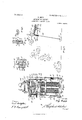
- Figure 1 is a longitudinal vertical section of my improved amusement device.
- Fig. 2 is a transverse vertical section upon line Qc of Fig. 1 looking toward the right.
- Fig. 3 is a diagrammatic view illustrating the movements of the vehicle during its transit through the air.
- Fig. l is a detail sectional view of a tension mechanism hereinafter described.
- Fig. 5 is a detail sectional view illustrating the manner of securing the side posts to the baseframe.
- Fig. is a transverse section upon line a a of Fig. 5.
- Fig. 7 is a transverse section of the track portion of a tilting platform hereinafter described, and
- Fig. 8 is a section upon line 8 8 of Fig. 1.
- the numeral 5 designates side base members.
- Bolts 6 eX- tend vertically through these side members 5, the heads 7 ofl said bolts entering recesses 8, formed in vertical side posts 9.
- Transverse openings 10 are formed through these side posts, and U-shaped wedge members 12 are adapted to be driven through these openings and to engage under the heads 7 of the bolts to draw nuts 1 1, carried upon the lower ends of the bolts, firmly against the under sides of the base members 5 to thereby bind the side posts
- Vertical standards 13 are secured in like manner by wedges 12 to the base members 5.
- Braces 14 enter notched portions 1 5 of the vertical side posts 9 5 and notched portions 16 of the base member 5. It will be readily understood that when iof the side posts 9 and base members 5.
- a tilting platform which is mounted upon a transverse shaft 17 is journaled in the side posts 9.
- This tilting platform is shown in transverse section in Fig. 7 and comprises longitudinally-extending I-beams 18.
- Struts 19 are secured to the transverse shaft 17 just inside of the side posts 9, and tie or brace rods 20, which extend from said struts or from plates 21, carried by said struts, to various portions of the tilting platform, serve to brace and strengthen the same.
- the Hoor of the outer end of the platform is made of a plurality of sections 22, the ends of these sections having fillingbloeks 23 secured thereto, which lie against the inner sides of the T-beams.
- Hooks 24, which are adapted to engage over the bases of the I- beams, have chains secured thereto.
- a U-bolt 32 carries nuts 33, which form stops for said bolt. In tying the parts together the U-bolt is inserted through the I-beam and through the outer portion of the shoe, after which a wedge 34 is driven down between the outer portion of the shoe and the U-bolt to wedge all of the parts firmly together.
- An inclined track 35 is supported by a standard 36.
- This inclined track may be of any desired length or inclination.
- a raised portion 37 is formed in this track.
- This inclined track proper terminates at 38 and has IIO hinged thereto at its terminal point by hinges 39 a leaf 40, the free edge of which overlies the inner section 22 of the platform-door.
- a trigger 41 is pivoted at 42 to a hanger 43, which is carried by the tilting platform. Secured to this trigger, as at 44, is a rod or cable 45, the opposite end of which engages at 46 with a latch 47.
- This latch is pivoted as at 48, to the rear end of the tilting platform and has a hooked end 49, which is adapted to engage with the transverse portion of a U- bar 50, carried by the standards 13.
- Transversely-disposed I-beams 51 arranged at the top of the standards 13, further brace and strengthen the structure, said I-beams having plates 51 secured to their ends, which are adapted to siide in sockets 13 in the standards 13.
- a buffer Carried by a transversely-disposed bar 52, which is secured to the vertical standards 13, is a buffer comprising the blocks 53 and 54, which have springs 55 interposed between them.
- This buffer is ada ted to cushion the rear end of the tilting p atform, as will be hereinafter set forth.
- Transversely-disposed beams 56 connect the rear ends of the I-beams 18. Secured to one of these beams are the upper ends of a plurality of coiled springs 57. The lower' ends of these springs are secured to a plate 58, which is carried by a transversely-disposed bar 59, arranged below the base mem bers 5. This bar is slidably disposed between guide members 60 and is adapted to be forced down to place the springs 57 under tension by means of hand-wheels 61, the stems 62 of which are threaded into plates 63, which are secured by fastening devices 64 to the base members 5. Bearing-blocks 65, carried by the bar 59, are adapted to receive the lower ends of the stems 62.
- a casing 67 Secured, as at 66, to the outer end of the tilting platform is a casing 67, in which a spring 68 is disposed.
- a plate 69 which is disposed between the spring and the upper end of said casing, has secured thereto one end of a cable 70, and the lower end of said cable is secured to an eyelet 71, carried by a weight 72.
- Tracks 73 serve to guide a vehicle 74 down the inclined track 35 and upon the tilting platform.
- Clamps 75 are adapted to clamp transversely-disposed bars 76 firmly against the opposite sides of the side posts 9 to brace said posts against lateral movement.
- the operation of the device is as follows: The vehicle to be thrown over is started down the incline 35.
- the speed at which the vehicle comes upon the tilting platform may be determined by the height of the rise 37 in the track, so that no matter how great the incline of the track 35 may be or how long said track may be by forming a raised portion 37 in the track of the proper elevation the vehicle 74 may be caused to come upon the tilting of the automobile are just leaving the front edge of the platform.
- the contact of the automobile with the trig er throws said trigger forward and pulls the lower end of the latch 47 forward.
- the spring 68 serves to cushion the forward end of the platforms as will be readily understood.
- the tension mechanism provided by the hand-wheels 61 and the transversely-disposed bar 59, to which the lower ends of thc springs are connected, provides means for placing the springs under any desired degree of tension, so that the same throw may be given the vehicle in every instance. After the necessary degree of tension has been ascertained by experiment and the springs have been set to that degree of tension the apparatus may be relied upon to give the proper throw to the vehicle to cause it to land right side up. This is an important feature in a device of this character.
- Machines of this sort are usually used in connection with amusements at parks or in connection with a circus. It is essential, therefore, in producing a practical device of this character to provide a structure which may be rapidly taken apart when it is desired to move from one place to another and is readily assembled when it is desired to erect the structure. When it is desired to take this structure apart, it is but necessary to remove the wedges 12 to disconnect the side posts 9 and the standards 13 from the base members. Knocking the wedges loose releases the transverse bars 76,' while the release of the side posts 9 of course releases the IOO IIO
- braces 14 The removal of the wedges 12 at the rear portion of the frame releases the standards 13, while the lower ends of the springs may be readily disconnected from the plates 58.
- the loop 28 is slipped from the end 27 of the lever 26, the I-beams 18 are permitted to move apart from each other to permit the sections 22 to be readily slipped from between said I-beams.
- the present structure provides simple and efficient means for performing a spectacular act, said structure being constructed in such manner that the operator may with certainty adjust it in such manner as to cause it to perform exactly the same action every time.
- Vhat I claim is- 1.
- a tilting platform pivoted intermediate its ends, and means for throwing one end of said platform into the air as and for the purpose set forth.
- the combination with a frame comprising a base -and vertical side posts having transverse openings formed therethrough, of headed members extending through the base and into said transverse opening, and U-shaped wedge members adapted to be driven into said transverse opening and to engage the heads of said headed members.
- a tilting platform comprising parallel longitudinally extending beams, a transversely-disposed beam adapted to connect said longitudinally-extending beams, and wedge members for locking the ends of said transversely-disposed members to the longitudinally-extending beams.
- a tilting platform comprising longitudinallyextending side beams, ooring-sections located between said side beams, members adapted to engage said side beams, flexible members connected to said members, and a lever to which the ends of said flexible members are connected in such manner that the movement of said lever will draw said beams toward each other.
Landscapes
- Handcart (AREA)
Description
PATPNTPD SEPT. 4, 1906. R. PPPP.
AMUSBMBNT DEVICE.
APPLIOATION PILPD APR.2v,19o.
2 SHEETS-SHEET 1.
TH: Nuxms Parkas co., wAsHINGraN. D. c.
PATENTED SEPT. 4, 1906. R. REPP. AMUSEMENT DEVICE.
APPLIUATION FILED APE.27,1906.
2 SHEETS-SHEET z.`
@Houma 5 nu: Nomus P515 ca., wAsHlNcroN, n. c.
to the base members.
ROY REPP, OF COLUMBUS, OHIO.
ANIUSENIENT DEVICE.
Specification of Letters Patent.
Patented Sept. 4, 1906.
Application filed April 27,1906. Serial No. 313,915.
.T all whom, it may concern:
Be it known that I, ROY REPP, a citizen of the United States, residing at Columbus, in the county of Franklin and State of Ohio, have invented certain new and useful lme provements in Amusement Devices, of which the following is a specification.
My invention relates to amusement devices, and has for its object the provision of means for causing an automobile or other vehicle to turn a somersault in the air.
A further object of the invention is the provision of mechanism adapted to throw an automobile bodily over in the air, said mechanism being constructed in such manner that the parts thereof may be readily assembled or disassembled when desired.
Further objects and advantages of the invention will be set forth in the detailed description which now follows.
in the accompanying drawings, Figure 1 is a longitudinal vertical section of my improved amusement device. Fig. 2 is a transverse vertical section upon line Qc of Fig. 1 looking toward the right. Fig. 3 is a diagrammatic view illustrating the movements of the vehicle during its transit through the air. Fig. lis a detail sectional view of a tension mechanism hereinafter described. Fig. 5 is a detail sectional view illustrating the manner of securing the side posts to the baseframe. Fig. is a transverse section upon line a a of Fig. 5. Fig. 7 is a transverse section of the track portion of a tilting platform hereinafter described, and Fig. 8 is a section upon line 8 8 of Fig. 1.
Like characters designate corresponding parts in all of the figures of the drawings.
Referring to the drawings, the numeral 5 designates side base members. Bolts 6 eX- tend vertically through these side members 5, the heads 7 ofl said bolts entering recesses 8, formed in vertical side posts 9. Transverse openings 10 are formed through these side posts, and U-shaped wedge members 12 are adapted to be driven through these openings and to engage under the heads 7 of the bolts to draw nuts 1 1, carried upon the lower ends of the bolts, firmly against the under sides of the base members 5 to thereby bind the side posts Vertical standards 13 are secured in like manner by wedges 12 to the base members 5. Braces 14 enter notched portions 1 5 of the vertical side posts 9 5 and notched portions 16 of the base member 5. It will be readily understood that when iof the side posts 9 and base members 5.
A tilting platform which is mounted upon a transverse shaft 17 is journaled in the side posts 9. This tilting platform is shown in transverse section in Fig. 7 and comprises longitudinally-extending I-beams 18. Struts 19 are secured to the transverse shaft 17 just inside of the side posts 9, and tie or brace rods 20, which extend from said struts or from plates 21, carried by said struts, to various portions of the tilting platform, serve to brace and strengthen the same. The Hoor of the outer end of the platform is made of a plurality of sections 22, the ends of these sections having fillingbloeks 23 secured thereto, which lie against the inner sides of the T-beams. Hooks 24, which are adapted to engage over the bases of the I- beams, have chains secured thereto. The ends of these chains are secured to a lever 26, the free end 27 of this lever being adapted to enter a loop 28. it will be readily understood that when this lever is drawn up, as shown in Fig. 7, and its free end engaged in the loop the chains will be drawn into such position as to bind the iii-beams firmly against the ends of the sections 22 of the platformfloor. A transversely-dis osed I-beam 29 braces the rear portion o the tilting platform and spaces the T-beams 18 from each other. The method of securing this transverse beam to the T-beams 18 is best illustrated in Fig. 8. By referring to said figure it will be seen that a shoe 30 is secured by bolts 31 to the transverse beam 29. The I- beam 18 and the portion of the shoe 30 which lies against said I-beam have slots formed therein which register with each other when the parts are in their assembled position, A U-bolt 32 carries nuts 33, which form stops for said bolt. In tying the parts together the U-bolt is inserted through the I-beam and through the outer portion of the shoe, after which a wedge 34 is driven down between the outer portion of the shoe and the U-bolt to wedge all of the parts firmly together.
An inclined track 35 is supported by a standard 36. This inclined track may be of any desired length or inclination. A raised portion 37 is formed in this track. This inclined track proper terminates at 38 and has IIO hinged thereto at its terminal point by hinges 39 a leaf 40, the free edge of which overlies the inner section 22 of the platform-door.
A trigger 41 is pivoted at 42 to a hanger 43, which is carried by the tilting platform. Secured to this trigger, as at 44, is a rod or cable 45, the opposite end of which engages at 46 with a latch 47. This latch is pivoted as at 48, to the rear end of the tilting platform and has a hooked end 49, which is adapted to engage with the transverse portion of a U- bar 50, carried by the standards 13. Transversely-disposed I-beams 51, arranged at the top of the standards 13, further brace and strengthen the structure, said I-beams having plates 51 secured to their ends, which are adapted to siide in sockets 13 in the standards 13.
Carried by a transversely-disposed bar 52, which is secured to the vertical standards 13, is a buffer comprising the blocks 53 and 54, which have springs 55 interposed between them. This buffer is ada ted to cushion the rear end of the tilting p atform, as will be hereinafter set forth.
Transversely-disposed beams 56 connect the rear ends of the I-beams 18. Secured to one of these beams are the upper ends of a plurality of coiled springs 57. The lower' ends of these springs are secured to a plate 58, which is carried by a transversely-disposed bar 59, arranged below the base mem bers 5. This bar is slidably disposed between guide members 60 and is adapted to be forced down to place the springs 57 under tension by means of hand-wheels 61, the stems 62 of which are threaded into plates 63, which are secured by fastening devices 64 to the base members 5. Bearing-blocks 65, carried by the bar 59, are adapted to receive the lower ends of the stems 62. Secured, as at 66, to the outer end of the tilting platform is a casing 67, in which a spring 68 is disposed. A plate 69, which is disposed between the spring and the upper end of said casing, has secured thereto one end of a cable 70, and the lower end of said cable is secured to an eyelet 71, carried by a weight 72.
The operation of the device is as follows: The vehicle to be thrown over is started down the incline 35. The speed at which the vehicle comes upon the tilting platform may be determined by the height of the rise 37 in the track, so that no matter how great the incline of the track 35 may be or how long said track may be by forming a raised portion 37 in the track of the proper elevation the vehicle 74 may be caused to come upon the tilting of the automobile are just leaving the front edge of the platform. The contact of the automobile with the trig er throws said trigger forward and pulls the lower end of the latch 47 forward. This releases said latch from the U-bar 50 and permits the springs 57, which are very powerful ones, to pull the rear end of the platform down and to consequently throw the front end of said platform up, at which time the angle-irons 18 will lie in the position indicated in dotted lines in Fig. 1, the buffer formed by the blocks 53 and 54 serving to cushion the rear end of the platform. The movement described by the vehicle has been diagrammatically illustrated in Fig. 3, from which it will be seen that at a the vehicle is very nearly upside down. At the front wheels are approximately directly over the rear wheels, while at c the machine has resumed its normal position and lands right side up, It will be obvious that if the trigger 41 be placed farther back, so that the latch 47 will be released before the front wheels of the vehicle leave the platform, said vehicle will describe a rear somersault instead of a forward somersault, as shown in Fig. 3. The spring 68 serves to cushion the forward end of the platforms as will be readily understood. The tension mechanism provided by the hand-wheels 61 and the transversely-disposed bar 59, to which the lower ends of thc springs are connected, provides means for placing the springs under any desired degree of tension, so that the same throw may be given the vehicle in every instance. After the necessary degree of tension has been ascertained by experiment and the springs have been set to that degree of tension the apparatus may be relied upon to give the proper throw to the vehicle to cause it to land right side up. This is an important feature in a device of this character.
Machines of this sort are usually used in connection with amusements at parks or in connection with a circus. It is essential, therefore, in producing a practical device of this character to provide a structure which may be rapidly taken apart when it is desired to move from one place to another and is readily assembled when it is desired to erect the structure. When it is desired to take this structure apart, it is but necessary to remove the wedges 12 to disconnect the side posts 9 and the standards 13 from the base members. Knocking the wedges loose releases the transverse bars 76,' while the release of the side posts 9 of course releases the IOO IIO
IVIS
braces 14. The removal of the wedges 12 at the rear portion of the frame releases the standards 13, while the lower ends of the springs may be readily disconnected from the plates 58. When the loop 28 is slipped from the end 27 of the lever 26, the I-beams 18 are permitted to move apart from each other to permit the sections 22 to be readily slipped from between said I-beams.
From the foregoing description it will be seen that the present structure provides simple and efficient means for performing a spectacular act, said structure being constructed in such manner that the operator may with certainty adjust it in such manner as to cause it to perform exactly the same action every time.
While the elements shown and described are well adapted to serve the purposes for which they are intended, it is to be understood that the invention is not limited to the precise construction set forth, but includes within its purview such changes as may be made within the scope of the appended claims.
Vhat I claim is- 1. In a device of the character described, a tilting platform pivoted intermediate its ends, and means for throwing one end of said platform into the air as and for the purpose set forth.
2. In a device of the character described, the combination with a tilting platform piv oted intermediate its ends and adapted to toss a vehicle into the air, of mechanism released by said vehicle for actuating said platform.
3. In a device of the character described, the combination with a tilting platform pivoted intermediate its ends and adapted to toss a vehicle into the air, of mechanism released by the movement of said vehicle for actuating said platform, and means for cushioning said platform at the end of its movement.
L1. In a device of the character described, the combination with a tilting platform pivoted intermediate its ends and adapted to toss a vehicle into the air, of mechanism adapted to actuate said latform, and means for varying the force o the movement imparted to said platform by said mechanism.
5. In a device of the character described, the combination with a tilting platform, of springs secured to the rear end of said platform and adapted to throw the front end of said platform into the air when released, and means for placing said springs under tension.
6. In a device of the character described, the combination with a tilting platform, of
4springs secured to the rear end of said platform, and mechanism adapted to place said springs under tension and to vary the tension of said springs at will.
7. In a device of the character described, the combination with a frame, comprising a base -and vertical side posts having transverse openings formed therethrough, of headed members extending through the base and into said transverse opening, and U-shaped wedge members adapted to be driven into said transverse opening and to engage the heads of said headed members.
8. In a device of the character described, the combination with a tilting platform comprising parallel longitudinally extending beams, a transversely-disposed beam adapted to connect said longitudinally-extending beams, and wedge members for locking the ends of said transversely-disposed members to the longitudinally-extending beams.
9. In a device of the character described, the combination with a supporting-frame, of a tilting platform, springs connected to the rear end of said tilting platform and to the frame which are adapted to throw the front end of the platform into the air, a latch to hold the rear end of the platform up against the action of said springs, a trigger located at the forward portion of the platform, and connections between said trigger and said latch whereby when said trigger is actuated said latch will be released.
10. In a device of the character described, a tilting platform comprising longitudinallyextending side beams, ooring-sections located between said side beams, members adapted to engage said side beams, flexible members connected to said members, and a lever to which the ends of said flexible members are connected in such manner that the movement of said lever will draw said beams toward each other.
In testimony whereof I afiix my signature in presence of two witnesses.
ROY REPP.
Witnesses:
FRANK G. CAMPBELL, CARL STOUGHTON.
IOO
Priority Applications (1)
| Application Number | Priority Date | Filing Date | Title |
|---|---|---|---|
| US31391506A US830004A (en) | 1906-04-27 | 1906-04-27 | Amusement device. |
Applications Claiming Priority (1)
| Application Number | Priority Date | Filing Date | Title |
|---|---|---|---|
| US31391506A US830004A (en) | 1906-04-27 | 1906-04-27 | Amusement device. |
Publications (1)
| Publication Number | Publication Date |
|---|---|
| US830004A true US830004A (en) | 1906-09-04 |
Family
ID=2898480
Family Applications (1)
| Application Number | Title | Priority Date | Filing Date |
|---|---|---|---|
| US31391506A Expired - Lifetime US830004A (en) | 1906-04-27 | 1906-04-27 | Amusement device. |
Country Status (1)
| Country | Link |
|---|---|
| US (1) | US830004A (en) |
-
1906
- 1906-04-27 US US31391506A patent/US830004A/en not_active Expired - Lifetime
Similar Documents
| Publication | Publication Date | Title |
|---|---|---|
| US830004A (en) | Amusement device. | |
| US594731A (en) | Machine for driving tie-plates | |
| US1225523A (en) | Lumber-stacker. | |
| US947902A (en) | Loading apparatus. | |
| US946282A (en) | Unloading apparatus. | |
| US1220332A (en) | Giant swing. | |
| US277484A (en) | Stump-extractor | |
| US1229507A (en) | Hay-stacker. | |
| US300407A (en) | tangney | |
| US181251A (en) | Improvement in lifting-jacks | |
| US888219A (en) | Hay-stacker. | |
| US391823A (en) | Fence-post or pile driving machine | |
| US616382A (en) | Ditching-machine | |
| US717962A (en) | Wagon-loading apparatus. | |
| US881408A (en) | Loading apparatus. | |
| US387934A (en) | wagaman | |
| US939703A (en) | Starting and separating gate. | |
| US504976A (en) | Loading device | |
| US789720A (en) | Machine for turning somersaults. | |
| US1491814A (en) | Haystacker | |
| US1317132A (en) | Sawing carriage | |
| US941238A (en) | Hay-stacker. | |
| US818306A (en) | Hangman's scaffold. | |
| US946913A (en) | Hoisting device. | |
| US2742166A (en) | Toy hay stacker |