US827770A - Electrostatic separator. - Google Patents
Electrostatic separator. Download PDFInfo
- Publication number
- US827770A US827770A US29838206A US1906298382A US827770A US 827770 A US827770 A US 827770A US 29838206 A US29838206 A US 29838206A US 1906298382 A US1906298382 A US 1906298382A US 827770 A US827770 A US 827770A
- Authority
- US
- United States
- Prior art keywords
- electrode
- electrodes
- electrical
- repelling
- plates
- Prior art date
- Legal status (The legal status is an assumption and is not a legal conclusion. Google has not performed a legal analysis and makes no representation as to the accuracy of the status listed.)
- Expired - Lifetime
Links
- 239000000463 material Substances 0.000 description 13
- XEEYBQQBJWHFJM-UHFFFAOYSA-N Iron Chemical compound [Fe] XEEYBQQBJWHFJM-UHFFFAOYSA-N 0.000 description 6
- 229910052742 iron Inorganic materials 0.000 description 3
- 230000007775 late Effects 0.000 description 3
- RYGMFSIKBFXOCR-UHFFFAOYSA-N Copper Chemical compound [Cu] RYGMFSIKBFXOCR-UHFFFAOYSA-N 0.000 description 2
- 229910000831 Steel Inorganic materials 0.000 description 2
- 229910052802 copper Inorganic materials 0.000 description 2
- 239000010949 copper Substances 0.000 description 2
- 230000005284 excitation Effects 0.000 description 2
- 239000011521 glass Substances 0.000 description 2
- 238000000926 separation method Methods 0.000 description 2
- 239000010959 steel Substances 0.000 description 2
- 229910001369 Brass Inorganic materials 0.000 description 1
- 241001424392 Lucia limbaria Species 0.000 description 1
- 239000010951 brass Substances 0.000 description 1
- 239000004020 conductor Substances 0.000 description 1
- 238000010276 construction Methods 0.000 description 1
- 229910052571 earthenware Inorganic materials 0.000 description 1
- 230000000694 effects Effects 0.000 description 1
- 230000005684 electric field Effects 0.000 description 1
- 239000002184 metal Substances 0.000 description 1
- 229910052751 metal Inorganic materials 0.000 description 1
- 239000000047 product Substances 0.000 description 1
- 239000000126 substance Substances 0.000 description 1
- 239000013589 supplement Substances 0.000 description 1
- 230000002459 sustained effect Effects 0.000 description 1
- 239000002023 wood Substances 0.000 description 1
Images
Classifications
-
- B—PERFORMING OPERATIONS; TRANSPORTING
- B03—SEPARATION OF SOLID MATERIALS USING LIQUIDS OR USING PNEUMATIC TABLES OR JIGS; MAGNETIC OR ELECTROSTATIC SEPARATION OF SOLID MATERIALS FROM SOLID MATERIALS OR FLUIDS; SEPARATION BY HIGH-VOLTAGE ELECTRIC FIELDS
- B03C—MAGNETIC OR ELECTROSTATIC SEPARATION OF SOLID MATERIALS FROM SOLID MATERIALS OR FLUIDS; SEPARATION BY HIGH-VOLTAGE ELECTRIC FIELDS
- B03C7/00—Separating solids from solids by electrostatic effect
- B03C7/02—Separators
- B03C7/12—Separators with material falling free
Definitions
- the electrical conditions at the separator-electrodes are improved and the contrast in electrical condition of those portions of the repelling-electrode which are immediately opposed tothe opposite electrode in relation to such portions as are not so immediately opposed is enhanced.
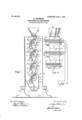
- Figure 1 is a vertical cross-section oi the entire machine, taken at the line 1 1 of Fig. 2; and Fig. 2 is a side elevation of the same, one of the sides of thev casing thereof being removed.
- the casing A is a rectangular box of conductive material composed, preierablyo f ⁇ sheet iron or steel, with a suitable, ⁇ angle-'iron Jframe. This case is mounted upon insulating-supports B, which vare preferably oi earthenware orporcelain orv which may under some conditions be'c'omposed of wood.
- insulating-supports B which vare preferably oi earthenware orporcelain orv which may under some conditions be'c'omposed of wood.
- hopper C Upon the top of the casing A there is mounted the hopper C, into which the material to be fed tov the ⁇ separator-electrodes is deposited.
- the hopper C terminates in a delivery-chute composed of two parallel plates D D', which are constructed ot electricallyconducting material, preferably sheet-steel.
- Four sets of electrodes are shown in the drawings, each set consisting of a pairnamely, the large metallic rotary electrode E and
- the electrode E of each pair is a metallic cylinder having, by preference, a brass or copper surface, which maybe of sheet vmetal or be electroplated upon an iron roller.
- the electrodes E are rotatively mounted in the ends of the casing, as at M, and are provided with suitable mechanism (not shown) for giving the electrodes E a rotary movement, (indicated by arrcws,) so as to carry material fed thereto from the hopper C to'- ward the electrode E'.
- the electrode E'- that is to say, the group of glass-insulated copper wires-is sustained by the casing, the ends N of the glass tubes passing through suitable perforations in the end walls of the -casing A.
- All of the electrodes E are c'onnected withv onepole of the generating or exciting mechanism, as by a'wire P, andthe ends@ all the relier-electrodes E are connected, as by a wire O, with the opposite pole or terminal of the exciting mechanism.
- suitable metallic clips F2 secured tO vtheinside of the end walls of .the casing A,
- the plates F, F', and G' are composed oi metal, preferably sheetsteel, and the lower set of plates F and F terminate in plates H and H', while a sheetmetal plate H2 extends downward, converging toward .the plate H' from the side of the casing A.
- spiral conveyers I Y' are rotatively mounted and serve to convey the separated materials endwise of the case to suitable points of delivery.
- the plates F, F', G, D, and D' are all in electrical metallic contact with the casing A and aretherefore in parallelelectrical communication with' the electrodes E and the terminal of the exciting apparatus (shown conventionally at x, Fig. 2) to which the wire O leads, (and also the wire 1),) While the electrode E' is insulated from the rest of the apparatus.
- These plates taken collectively, form an electric shield or inclosure around those parts of the repelling-electrode E which are not in immediate opposition to the opposed elecwhich 4 IOO trode E', so lthat these plates constitute in substance an inclosing case or box for the rotary electrode.
- the lower pairs of electrodes in the series serving to supplement the separation accom lished by the-first ,air.
- the plates Fl? F, and G in this em odiment of my invention are made to perform a mechanical as well as an electrical function in that the plate G diverts the heads of the separate material into one region in the casing, While the lates F and F collect the tails which fall rom the surface of the electrode E or are brushed therefrom by the wipers K and deliver them at the narrow chutes formed by the lower edges F F of these plates to the next succeeding electrode.
- the heterogeneous material delivered to the surface of the rotary repelling-electrodes E is subjected to the full separative effect of the electrical field While it is passing through that region which lies immediately opposed to the electrode E; but in its further progress that portion of the material which has not been re pelled while passing through this region goes into an inclosed space, wherein no electrical@ excitation is manifested, this inclosed space being, in eect, the interior of'a hollow conducting-body Within which, however great the external excitation may be, no electrical charge can penetrate.
- a repelling-electrode means to feed material thereto, an opposed electrode, electrical exciting mechanism and connections therefrom to the electrodes, and an electrically-conducting shield, surrounding portions of the repelling-electrode which are not in immediate op osition to the opposed electrode, said s ield being electrically connected with the exciting apparatus in parallel with the repelling-electrode.
- the 'combination of a repelling-electrode, an opposed electrode means to feed material to the el'ectrode including a metallic delivery-chute, metallic lates to distribute separated products, sai plates surrounding portions of the repelling-e ectrode which are not in immediate opposition to the opposed electrode, and electrical exciting mechanism, with connections to the electrodes and to the metallic delivery-chute and distributing-plates, the chute, plates, and repelling-electrode being connected to the same terminal of the exciting mechanism.
Landscapes
- Electrostatic Separation (AREA)
Description
PATENTED AUG. 7,. 19661 M. WQDSM'B.
BLBGTROSTATIG SEPARATOR.
Apenmnmn funn JAN. 2a, naar= SVENTBQ UNITED PATENT OFFICE.
MILLARD WOODSOME, OF BOSTON, MASSACHUSETTS, ASSIGNOR- TO H UFF ELECTROSTATTC SEPARATOB COMPANY, OF BOSTON, MAS- SACHUSETTS, A CORPORATION OF MAINE.
' ELEGTROSTATIG SEPARATOR.
Speccation of Letters Patent.
:Patented Aug. 7, ieee.v
Application filed January 29, 1906. Serial Nox 298.382.
To @ZZ-107110791, it may concern.-
Be it known that I, MiLLARD WooDsoME,
va citizen of the United States, and a resident ments hereinbelow to be described whereby.
the electrical conditions at the separator-electrodes are improved and the contrast in electrical condition of those portions of the repelling-electrode which are immediately opposed tothe opposite electrode in relation to such portions as are not so immediately opposed is enhanced.
In the drawings hereto annexed, which illustrate an embodiment of my invention and improvements,y Figure 1 is a vertical cross-section oi the entire machine, taken at the line 1 1 of Fig. 2; and Fig. 2 is a side elevation of the same, one of the sides of thev casing thereof being removed.
The source of electrical energy whereby the electrostatic separator is excited is not herein shown. 'Anv desired exciting devices may be employed; but l prefer to use the electrical machinery which is shown and described in its essential com onents in United StatesLetters Patent o. 796,011, dated August 1, 1905, issued to Charles H.
,Huit as assignee of Greenleaf W. Fickard.
The casing A is a rectangular box of conductive material composed, preierablyo f` sheet iron or steel, with a suitable,` angle-'iron Jframe. This case is mounted upon insulating-supports B, which vare preferably oi earthenware orporcelain orv which may under some conditions be'c'omposed of wood. Upon the top of the casing A there is mounted the hopper C, into which the material to be fed tov the`separator-electrodes is deposited. The hopper C terminates in a delivery-chute composed of two parallel plates D D', which are constructed ot electricallyconducting material, preferably sheet-steel. Four sets of electrodes are shown in the drawings, each set consisting of a pairnamely, the large metallic rotary electrode E and a gridiion ot stationary electrodes E',
the latter consisting, preferably, of small copper wires, each inclosed in a thick glass tube. The electrode E of each pair is a metallic cylinder having, by preference, a brass or copper surface, which maybe of sheet vmetal or be electroplated upon an iron roller.
The electrodes E are rotatively mounted in the ends of the casing, as at M, and are provided with suitable mechanism (not shown) for giving the electrodes E a rotary movement, (indicated by arrcws,) so as to carry material fed thereto from the hopper C to'- ward the electrode E'. The electrode E'- that is to say, the group of glass-insulated copper wires-is sustained by the casing, the ends N of the glass tubes passing through suitable perforations in the end walls of the -casing A. All of the electrodes E are c'onnected withv onepole of the generating or exciting mechanism, as by a'wire P, andthe ends@ all the relier-electrodes E are connected, as by a wire O, with the opposite pole or terminal of the exciting mechanism. Upon suitable metallic clips F2, secured tO vtheinside of the end walls of .the casing A,
there are mounted the inclined plates F, F', and G', the plates F being continued upwardly and then inwardly toward the electrode E, where theyprovide a proper mounting for the wipers K. The plates F, F', and G are composed oi metal, preferably sheetsteel, and the lower set of plates F and F terminate in plates H and H', while a sheetmetal plate H2 extends downward, converging toward .the plate H' from the side of the casing A. In the bottom of the a paratus there are shown. spiral conveyers I Y', are rotatively mounted and serve to convey the separated materials endwise of the case to suitable points of delivery.
The plates F, F', G, D, and D' are all in electrical metallic contact with the casing A and aretherefore in parallelelectrical communication with' the electrodes E and the terminal of the exciting apparatus (shown conventionally at x, Fig. 2) to which the wire O leads, (and also the wire 1),) While the electrode E' is insulated from the rest of the apparatus. These plates, taken collectively, form an electric shield or inclosure around those parts of the repelling-electrode E which are not in immediate opposition to the opposed elecwhich 4 IOO trode E', so lthat these plates constitute in substance an inclosing case or box for the rotary electrode. The lines of force established between the two electrodes roceed directly from the electrode E to the e ectrode E in the region of their greatest density, but indirectly from the lates D, D,"F, F, and G to the electrode E the density of lines of force is least, and that portion of the surface of the re elling-electrode E which is inclosed by this metallic sheath is electrostatically shielded from the electrode E and is therefore electrically inert, and thus in its electrical condition is much more sharply contrasted with the electrical condition of that portion which isimmediately opposed to the electrode E than has heretofore been the case when the electrode E or its equivalent has not been inclosed in any electrically-active sheath.
In the construction herein shown there is provided a series of electrode pairs E E', to which the material is conducted in vertical succession, the lower pairs of electrodes in the series serving to supplement the separation accom lished by the-first ,air. Thus the plates Fl? F, and G in this em odiment of my invention are made to perform a mechanical as well as an electrical function in that the plate G diverts the heads of the separate material into one region in the casing, While the lates F and F collect the tails which fall rom the surface of the electrode E or are brushed therefrom by the wipers K and deliver them at the narrow chutes formed by the lower edges F F of these plates to the next succeeding electrode.
By the means above described the heterogeneous material delivered to the surface of the rotary repelling-electrodes E is subjected to the full separative effect of the electrical field While it is passing through that region which lies immediately opposed to the electrode E; but in its further progress that portion of the material which has not been re pelled while passing through this region goes into an inclosed space, wherein no electrical@ excitation is manifested, this inclosed space being, in eect, the interior of'a hollow conducting-body Within which, however great the external excitation may be, no electrical charge can penetrate. 1t has been observed in actual practice that, other things being `equal and other conditions remaining the same, a more effective separation of materials is accomplished with the designedly inactive areas of the .re elling-electrode inclosed by an electrical y-conducting shieldV om those regions where than when these improvements are not employed.
What I claim, and desire to secure by Letters Patent, is-
1. `In an electrostatic separator, the combination of a repelling-electrode, means to feed material thereto, an opposed electrode, electrical exciting mechanism and connections therefrom to the electrodes, and an electrostatic shield inclosing and shielding portions of the repelling-electrode which are not in immediate opposition to the opposed electrode.
2. In an electrostatic separator, the combination of a repelling-electrode, means to feed material thereto, an opposed electrode, electrical exciting mechanism and connections therefrom to the electrodes, and an electrically-conducting shield, surrounding portions of the repelling-electrode which are not in immediate op osition to the opposed electrode, said s ield being electrically connected with the exciting apparatus in parallel with the repelling-electrode. I 3. In an electrostatic separator, the 'combination of a repelling-electrode, an opposed electrode, means to feed material to the el'ectrode including a metallic delivery-chute, metallic lates to distribute separated products, sai plates surrounding portions of the repelling-e ectrode which are not in immediate opposition to the opposed electrode, and electrical exciting mechanism, with connections to the electrodes and to the metallic delivery-chute and distributing-plates, the chute, plates, and repelling-electrode being connected to the same terminal of the exciting mechanism.
4. in an electrostatic separator, the combination of a metallic casing, insulating-supports therefor, a repelling-'eleotroda an opposite electrode, a hopper, a metallic delivery-chute therefor to deliver material to the repelling-electrode, a metallic shield r'ote'cting such portions of the repclling-e ect'rode as are not in immediate opposition to the opposite electrode, the repelling-electrode, hopper-delivery chute, and shield being within and in electrical contact with the casing, and electrical exciting mechanism and connections therefrom to the several electrodes.
Signed by me at Boston, Massachusetts, this 24th day of January, 1 906.
MILLARD VOODSOME.
Witnesses:
JOSEPH T. BRENNAN, C. D. WOODBERRY.
roo
IIO
Priority Applications (1)
| Application Number | Priority Date | Filing Date | Title |
|---|---|---|---|
| US29838206A US827770A (en) | 1906-01-29 | 1906-01-29 | Electrostatic separator. |
Applications Claiming Priority (1)
| Application Number | Priority Date | Filing Date | Title |
|---|---|---|---|
| US29838206A US827770A (en) | 1906-01-29 | 1906-01-29 | Electrostatic separator. |
Publications (1)
| Publication Number | Publication Date |
|---|---|
| US827770A true US827770A (en) | 1906-08-07 |
Family
ID=2896249
Family Applications (1)
| Application Number | Title | Priority Date | Filing Date |
|---|---|---|---|
| US29838206A Expired - Lifetime US827770A (en) | 1906-01-29 | 1906-01-29 | Electrostatic separator. |
Country Status (1)
| Country | Link |
|---|---|
| US (1) | US827770A (en) |
Cited By (6)
| Publication number | Priority date | Publication date | Assignee | Title |
|---|---|---|---|---|
| US20050061713A1 (en) * | 2000-07-27 | 2005-03-24 | Gates Peter J. | Apparatus for the electrostatic separation of particulate mixtures |
| US20170198394A1 (en) * | 2016-01-13 | 2017-07-13 | Product Innovation and Engineering L.L.C. | Electrostatic powder feeder |
| US20180243769A1 (en) * | 2017-02-24 | 2018-08-30 | Powder Motion Labs, LLC | Electrostatic powder feeder |
| US10800615B2 (en) | 2018-03-16 | 2020-10-13 | Power Motion Labs, LLC | Electrostatic conveyor-wheel powder feeder |
| US11772164B2 (en) | 2020-03-18 | 2023-10-03 | Powder Motion Labs, LLC | Powder bed recoater |
| US11872754B2 (en) | 2020-03-18 | 2024-01-16 | Powder Motion Labs, LLC | Recoater using alternating current to planarize top surface of powder bed |
-
1906
- 1906-01-29 US US29838206A patent/US827770A/en not_active Expired - Lifetime
Cited By (10)
| Publication number | Priority date | Publication date | Assignee | Title |
|---|---|---|---|---|
| US20050061713A1 (en) * | 2000-07-27 | 2005-03-24 | Gates Peter J. | Apparatus for the electrostatic separation of particulate mixtures |
| US7041925B2 (en) * | 2000-07-27 | 2006-05-09 | Ore Kinetics Investments Pty., Ltd. | Apparatus for the electrostatic separation of particulate mixtures |
| US20170198394A1 (en) * | 2016-01-13 | 2017-07-13 | Product Innovation and Engineering L.L.C. | Electrostatic powder feeder |
| US10035219B2 (en) * | 2016-01-13 | 2018-07-31 | Product Innovation and Engineering L.L.C. | Electrostatic powder feeder |
| US20180243769A1 (en) * | 2017-02-24 | 2018-08-30 | Powder Motion Labs, LLC | Electrostatic powder feeder |
| US10213797B2 (en) * | 2017-02-24 | 2019-02-26 | Powder Motion Labs, LLC | Electrostatic powder feeder |
| US10226780B2 (en) * | 2017-02-24 | 2019-03-12 | Powder Motion Labs, LLC | Electrostatic powder feeder with vibratory assist |
| US10800615B2 (en) | 2018-03-16 | 2020-10-13 | Power Motion Labs, LLC | Electrostatic conveyor-wheel powder feeder |
| US11772164B2 (en) | 2020-03-18 | 2023-10-03 | Powder Motion Labs, LLC | Powder bed recoater |
| US11872754B2 (en) | 2020-03-18 | 2024-01-16 | Powder Motion Labs, LLC | Recoater using alternating current to planarize top surface of powder bed |
Similar Documents
| Publication | Publication Date | Title |
|---|---|---|
| US2983847A (en) | Apparatus for grounding electrostatic charges | |
| US827770A (en) | Electrostatic separator. | |
| US1549875A (en) | Method of separating poorly-conducting fibrous and granular materials | |
| US3716755A (en) | Electrostatic charging and discharging apparatus | |
| US1400795A (en) | Apparatus for the electrical treatment of gases | |
| US2752533A (en) | Apparatus for the eduction of electrostatic charges from the surface of materials of poor electrical conductivity | |
| US2654438A (en) | Electrical precipitator | |
| US2987137A (en) | Particle charging apparatus for electrostatic filter | |
| US1297159A (en) | Electric separator. | |
| US1344330A (en) | Orifice-precipitator | |
| US840802A (en) | Electrostatic separator. | |
| US1829565A (en) | Ore concentration | |
| US2225096A (en) | Electrostatic separator | |
| US977570A (en) | Process of electrostatic magnetic separation. | |
| US1541677A (en) | Apparatus for electrical precipitation of suspended particles from gases | |
| US801380A (en) | Apparatus for electrostatic separation of substances of diverse electric susceptibilities. | |
| US2885599A (en) | Charge transferring means for electrostatic generators | |
| US899364A (en) | Electric separator. | |
| US910664A (en) | Magnetic separator. | |
| US805694A (en) | Method of electrostatic separation. | |
| US775123A (en) | Apparatus for electrically treating gases. | |
| US997322A (en) | Electrostatic separator. | |
| US675162A (en) | Magnetic separator. | |
| SU1331567A1 (en) | Corona-type electrostatic separator | |
| US1017701A (en) | Electrostatic separator. |