US8275474B2 - Flexible multichannel outputs for dual audio decode - Google Patents
Flexible multichannel outputs for dual audio decode Download PDFInfo
- Publication number
- US8275474B2 US8275474B2 US11/581,394 US58139406A US8275474B2 US 8275474 B2 US8275474 B2 US 8275474B2 US 58139406 A US58139406 A US 58139406A US 8275474 B2 US8275474 B2 US 8275474B2
- Authority
- US
- United States
- Prior art keywords
- audio
- mixers
- program
- output
- mix
- Prior art date
- Legal status (The legal status is an assumption and is not a legal conclusion. Google has not performed a legal analysis and makes no representation as to the accuracy of the status listed.)
- Expired - Fee Related, expires
Links
- 230000009977 dual effect Effects 0.000 title description 3
- 238000000034 method Methods 0.000 claims abstract description 15
- 239000000872 buffer Substances 0.000 claims description 64
- 230000000694 effects Effects 0.000 claims description 21
- 238000012856 packing Methods 0.000 claims description 2
- 230000008878 coupling Effects 0.000 claims 7
- 238000010168 coupling process Methods 0.000 claims 7
- 238000005859 coupling reaction Methods 0.000 claims 7
- 101100184148 Xenopus laevis mix-a gene Proteins 0.000 description 8
- 101100345673 Xenopus laevis mix-b gene Proteins 0.000 description 6
- 101000912503 Homo sapiens Tyrosine-protein kinase Fgr Proteins 0.000 description 4
- 102100026150 Tyrosine-protein kinase Fgr Human genes 0.000 description 4
- PCHJSUWPFVWCPO-UHFFFAOYSA-N gold Chemical compound [Au] PCHJSUWPFVWCPO-UHFFFAOYSA-N 0.000 description 3
- 239000010931 gold Substances 0.000 description 3
- 229910052737 gold Inorganic materials 0.000 description 3
- 238000012545 processing Methods 0.000 description 3
- 101100015484 Saccharomyces cerevisiae (strain ATCC 204508 / S288c) GPA1 gene Proteins 0.000 description 2
- 240000007817 Olea europaea Species 0.000 description 1
- 230000003044 adaptive effect Effects 0.000 description 1
- 238000006243 chemical reaction Methods 0.000 description 1
- 230000003111 delayed effect Effects 0.000 description 1
- 230000001419 dependent effect Effects 0.000 description 1
- 238000013461 design Methods 0.000 description 1
- 238000001914 filtration Methods 0.000 description 1
- 238000012552 review Methods 0.000 description 1
- 230000001360 synchronised effect Effects 0.000 description 1
- 239000010981 turquoise Substances 0.000 description 1
Images


Classifications
-
- H—ELECTRICITY
- H04—ELECTRIC COMMUNICATION TECHNIQUE
- H04N—PICTORIAL COMMUNICATION, e.g. TELEVISION
- H04N21/00—Selective content distribution, e.g. interactive television or video on demand [VOD]
- H04N21/80—Generation or processing of content or additional data by content creator independently of the distribution process; Content per se
- H04N21/81—Monomedia components thereof
- H04N21/8106—Monomedia components thereof involving special audio data, e.g. different tracks for different languages
-
- H—ELECTRICITY
- H04—ELECTRIC COMMUNICATION TECHNIQUE
- H04N—PICTORIAL COMMUNICATION, e.g. TELEVISION
- H04N21/00—Selective content distribution, e.g. interactive television or video on demand [VOD]
- H04N21/40—Client devices specifically adapted for the reception of or interaction with content, e.g. set-top-box [STB]; Operations thereof
- H04N21/47—End-user applications
- H04N21/485—End-user interface for client configuration
- H04N21/4852—End-user interface for client configuration for modifying audio parameters, e.g. switching between mono and stereo
-
- H—ELECTRICITY
- H04—ELECTRIC COMMUNICATION TECHNIQUE
- H04N—PICTORIAL COMMUNICATION, e.g. TELEVISION
- H04N5/00—Details of television systems
- H04N5/44—Receiver circuitry for the reception of television signals according to analogue transmission standards
- H04N5/60—Receiver circuitry for the reception of television signals according to analogue transmission standards for the sound signals
- H04N5/602—Receiver circuitry for the reception of television signals according to analogue transmission standards for the sound signals for digital sound signals
-
- H—ELECTRICITY
- H04—ELECTRIC COMMUNICATION TECHNIQUE
- H04N—PICTORIAL COMMUNICATION, e.g. TELEVISION
- H04N21/00—Selective content distribution, e.g. interactive television or video on demand [VOD]
- H04N21/40—Client devices specifically adapted for the reception of or interaction with content, e.g. set-top-box [STB]; Operations thereof
- H04N21/47—End-user applications
- H04N21/485—End-user interface for client configuration
Definitions
- the present invention relates generally to audio outputs and, more particularly, to the implementation of flexible multichannel outputs for dual audio decode.
- STBs Set top boxes for satellite and digital cable have various audio outputs. These various audio outputs enable audio for a program to be delivered on one or more outputs simultaneously. For conventional STBs that can handle only a single program, there is no flexibility to simultaneously play a second program.
- a system and/or method for flexible multichannel outputs for dual audio decode substantially as shown in and/or described in connection with at least one of the figures, as set forth more completely in the claims.
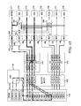
- FIG. 1 illustrates an embodiment of an audio delivery system in accordance with the present invention.
- FIG. 2 illustrates an embodiment of an audio switching block.
- FIG. 3 illustrates a flowchart of a process of flexibly delivering audio program(s) to various audio outputs.
- FIGS. 4A-4E illustrate example usage modes that are enabled through the audio delivery system of the present invention.
- Audio systems can be designed to support a variety of audio outputs, including the Sony/Philips Digital Interconnect Format (SPDIF), multi-format audio interface (MAI) such as High-Definition Multimedia Interface (HDMI), Inter-IC Sound (I2S), analog outputs, or the like. It is a feature of the present invention that audio from a plurality of programs can be flexibly routed to the particular outputs that are desired for each audio stream. This flexibility enables the audio system to operate in a variety of configured usage modes, wherein each usage mode identifies the routing of each audio stream to one or more outputs.
- SPDIF Sony/Philips Digital Interconnect Format
- MAI multi-format audio interface
- HDMI High-Definition Multimedia Interface
- I2S Inter-IC Sound
- the audio output system of FIG. 1 includes digital signal processor (DSP) block 110 , which can be configured to simultaneously decompress one or more compressed streams (e.g., MPEG, Dolby Digital, MPEG-2 AAC, MPEG-4 AAC, and Dolby Digital Plus audio services).
- DSP 110 can be configured to simultaneously decompress two compressed streams.
- the simultaneous decompressing of two compressed streams enables DSP 110 to simultaneously output two distinct audio streams on two different audio outputs.
- DSP 110 can enable the output of a first digital audio service in compressed form on SPDIF and a second digital audio service in a non-compressed form on HDMI.
- DSP 110 retrieves a compressed audio stream that is stored in compressed data buffer and index table buffer pair N (CDB/ITB-N) of DRAM 120 .
- the processing actions performed by DSP 110 on the compressed audio stream would depend on the intended audio output(s) to which the audio stream would be delivered.
- the retrieved audio stream data can be decoded and downmixed into uncompressed stereo for delivery to SPDIF, HDMI, digital-to-analog converter (DAC), or I2S outputs, decoded and separated into multichannel outputs (e.g., 5.1 or 7.1 audio) for delivery to HDMI or I2S outputs, packed for delivery to SPDIF output, variably delayed for different outputs, converted to another format (e.g., AC3) for delivery, etc.
- multichannel outputs e.g., 5.1 or 7.1 audio
- the processed audio stream generated by DSP 110 is then stored in selected ring buffer(s) (i.e., RB 0 -RB 15 ) of memory 120 .
- a ring buffer can be designed to store mono, interleaved stereo, or paired with another ring buffer for separate left/right channels.
- RB 1 and RB 9 can be selected to store the left and right audio channels for the processed audio stream.
- a ring buffer pair can be used to store unprocessed data such as audio effect data that is to be subsequently combined with other processed audio stream data stored in ring buffers in memory 120 . As will be described in greater detail below, this mixing can occur in data path blocks 142 , 144 .
- Audio stream data stored in ring buffers RB 0 -RB 15 are retrieved and stored in source channels 0 - 7 (S_CH 0 -S_CH 7 ) of buffer block 130 , which can provide a time delay with optional adaptive rate filtering.
- each of S_CH 0 -S_CH 7 stores a pair of audio channels. Audio stream data stored in buffer block 130 is then provided to data path blocks 142 , 144 .
- ring buffers and/or source channels can be used other than those illustrated in FIG. 1 .
- the resources can be allocated as follows:
- each data path block 142 , 144 provides mixing and multiplexing of audio stream data.
- each data path block 142 , 144 is designed to support four input audio streams and four output audio streams.
- Each data path block 142 , 144 is also designed to allow up to three inputs to be mixed for each output. More specifically, each output can represent a mix of three independently selected inputs.
- MIX 0 can represent a mix of inputs 1 , 2 , and 4
- MIX 1 can represent a mix of inputs 2 , 3 , and 4 .
- the independent selection of inputs for each output is facilitated by a crossbar switch.
- the specific number of input and output audio streams chosen as well as the extent of the mixing capabilities for the outputs would represent implementation dependent design decisions.
- data path blocks 142 , 144 can support distinct time bases and sample rates on each output. Data path blocks 142 , 144 can also perform a low-fidelity sample rate conversion intended for matching the sample rate on sound effects to the sample rate of the decoded or analog audio.
- the mixers (MIX 0 -MIX 3 ) in data path block 142 and the mixers (MIX 4 -MIX 7 ) in data path block 144 each feed selected audio buffers 161 - 168 that are each associated with particular audio output destinations.
- the audio system supports a variety of output destinations including the following:
- buffer 161 is associated with SPDIF generator 171
- buffer 162 is associated with MAI bus 172
- buffer 163 is associated with audio DAC 0 173
- buffer 164 is associated with I2S 0 converter 174
- buffer 165 is associated with I2S 2 converter 175
- buffer 166 is associated with flex converter 176
- buffer 167 is associated with audio DAC 1 177
- buffer 168 is associated with I2S 1 converter 178 .
- selector 182 can be used to couple buffer 161 with MAI bus 172 . Selector 182 therefore enables the audio stream data routed to SPDIF generator 171 to also be routed to MAI bus 172 . Selector 182 can also be configured to route multichannel outputs (e.g., 5.1 or 7.1 audio) for delivery to MAI bus 172 . As illustrated, these multichanel outputs are routed from buffers 164 , 165 , 166 , and 168 as a four-pair bus to MAI 172 .
- Selector 184 can be used to couple buffers 161 and 162 to flex converter 176 . Selector 184 therefore enables the audio stream data routed to SPDIF generator 171 or MAI bus 172 to also be routed to flex converter 176 .
- the various routing possibilities enabled by the audio system of FIG. 1 will be described in greater detail below.
- MIX 0 and MIX 1 output from data path block 142 are routed to micro sequencer (MS) 150 prior to buffers 161 and 162 .
- MS 150 is designed to handle the bit stream packing for SPDIF generator 171 and MAI bus 172 .
- the audio system framework of FIG. 1 enables audio stream data from one or more programs to be output to one or more of SPDIF, HDMI, I2S, DAC, and flex audio outputs.
- the particular routing of audio programs to the various outputs can be based on defined configurations of the audio system, wherein each configuration describes how to connect various sources to each particular output.
- the configurations can define various output options. For example, audio stream data can be output in analog format through one or both of the two stereo DAC blocks, the audio stream data can be output over an I2S for connection to an off-chip DAC, the audio stream data can be output on SPDIF for digital connection to an A/V amplifier/receiver, or the audio stream data can be combined with video via an HDMI interface.
- the flexible routing framework of the present invention is enabled in part by the switching capabilities of data path blocks 142 , 144 .
- data path blocks 142 , 144 To illustrate the operation of data path blocks 142 , 144 in greater detail, reference is now made to the illustration of FIG. 2 , which shows an example configuration of data path block 142 .
- data path block 142 includes four inputs (SRC 0 -SRC 3 ), three of which (SRC 0 -SRC 2 ) are configured to receive compressed audio, audio effect, and decoded audio (downmix) inputs, respectively.
- the three audio inputs are then routed to the appropriate mixers (MIX 0 -MIX 3 ) as follows: MIX 0 is coupled solely to input SRC 0 , MIX 1 is coupled to inputs SRC 1 and SRC 2 , MIX 2 is coupled to inputs SRC 1 and SRC 2 , and MIX 3 is coupled to inputs SRC 1 and SRC 2 .
- each of mixers MIX 0 -MIX 3 can be independently coupled to up to three of inputs SRC 0 -SRC 3 .
- MIX 0 is coupled to one input SRC 0
- each of MIX 1 -MIX 3 are coupled to the two inputs SRC 1 and SRC 2 .
- the effect of this configuration of the crossbar is that the compressed audio is passed on to MIX 0 for delivery, for example, to SPDIF and MAI outputs, while the audio effect and the downmixed decoded audio are each mixed in MIX 1 -MIX 3 to produce a mixed audio output that can be delivered, for example, to DAC or I2S outputs.
- the flexible routing of audio streams to selected outputs can be enabled through defined configuration modes.
- This configuration mode can be used to identify the particular inputs to be generated and the routing of such inputs to the selected outputs.
- one configuration mode can be defined such that the main compressed data is decoded and mixed with an audio effect and sent to SPDIF, HDMI, I2S 0 , and DAC 0 outputs.
- a configuration mode can be defined such that the main compressed data is decoded and mixed with an audio effect and sent to I2S 0 and DAC 0 outputs, while compressed data is passed through to SPDIF and HDMI outputs.
- DSP 110 processes the audio data and stores it in memory 120 .
- the extent of the processing performed by DSP 110 is based on the determined configuration mode. If the configuration mode specifies that only uncompressed stereo is to be sent to one or more output destinations, than DSP 110 would decode the compressed data. If the configuration mode specifies that AC3 data is to be delivered to the SPDIF output in addition to uncompressed stereo, than DSP 110 would convert compressed data to the AC3 format and decode the compressed data.
- the audio data is retrieved from memory and buffered in buffer block 130 . More specifically, audio data is transferred from ring buffers in memory 120 to source channels in buffer block 130 . As illustrated in the embodiment of FIG. 1 , the source channels S_CHn are associated with input sources of data path blocks 142 , 144 . Accordingly, the source channel S_CHn is chosen at least in part on the configuration mode of the audio system.
- the mixing and path routing in the audio system is configured in accordance with the configuration mode. As described with reference to FIG. 2 , this mixing and path routing is based in part on the configuration of the crossbar switches within data path blocks 142 , 144 . These crossbar switches dictate the particular set of input sources that are to be mixed in each mixer. The output of those mixers is then passed on to their respective buffers. From here, as illustrated in the embodiment of FIG. 1 , further path routing can be determined by selectors 182 and 184 . These selectors determine the specific outputs that are transferred to the output destinations 171 - 178 . For example, selector 182 can determine whether the audio stream sent to SPDIF generator 171 is also sent to MAI bus 172 .
- the audio system can then output the audio stream data from one or more programs in the output formats identified by the configuration mode.
- FIG. 4A illustrates a configuration mode that decodes compressed data (shown in red) and sends it to I2S 0 and DAC 0 .
- the sound effects (shown in blue) are stored in RB 1 and RB 9 , while the decoded data is stored in RB 2 and RB 10 .
- the sound effect data is passed through S_CH 1 and sent to MIX 2 and MIX 3 via the crossbar of data path block 142 .
- the decoded data is passed through S_CH 2 and also sent to MIX 2 and MIX 3 via the crossbar of data path block 142 .
- Both the decoded data and the sound effect data are then mixed by MIX 2 and MIX 3 to produce mixed data (shown in purple). This mixed data is then routed to audio DAC 0 173 and I2S 0 converter 174 via buffers 163 and 164 , respectively.
- the compressed data (shown in yellow) can also be passed through to SPDIF and HDMI outputs.
- the compressed data is stored in RB 0 and is passed through S_CH 0 to MIX 0 .
- the compressed data is sent through MS 150 , through buffer 161 and onto SPDIF generator 171 .
- Selector 172 is also configured to route the output of buffer 161 to MAI bus 172 .
- This example configuration mode can be used for Dolby Digital data where an advanced HDMI receiver is available that understands compressed Dolby Digital data.
- FIG. 4B illustrates a configuration mode that sends decoded data to audio DAC 0 173 and I2S 0 converter 174 , and sends compressed data to SPDIF generator 171 , in the same manner as the configuration mode of FIG. 4A .
- MAI bus 172 receives decoded data instead of compressed data.
- the crossbar of data path block 142 now routes downmixed and decoded data to MIX 1 in addition to MIX 2 and MIX 3 .
- MIX 2 then passes the mixed data (shown in purple) output by MIX 1 to MAI bus 172 via MS 150 and buffer 162 .
- selector 172 is now configured to select the output generated by buffer 162 , instead of buffer 161 .
- the configuration mode of FIG. 4B decodes compressed data, mixes it with sound effect data, and sends it to I2S 0 , DAC 0 , and HDMI.
- the compressed data on the other hand, is passed through to SPDIF (shown in gold).
- SPDIF shown in gold
- FIG. 4C illustrates a configuration mode that sends decoded data to audio DAC 0 173 and I2S 0 converter 174 in the same manner as the configuration mode of FIG. 4A .
- SPDIF generator 171 receives decoded data instead of compressed data.
- the crossbar of data path block 142 routes both the decoded data and audio effect data to MIX 0 , which then sends the mixed data (shown in purple) to SPDIF generator 171 via MS 150 and buffer 161 .
- the crossbar of data path block 142 has also been configured such that compressed data (shown in gold) is now routed from S_CH 0 to MIX 1 . MIX 1 then outputs the compressed data to MAI bus 172 via MS 150 and buffer 162 .
- this configuration mode decodes compressed data and sends it to I2S 0 , DAC 0 , and SPDIF.
- the compressed data is passed through to HDMI.
- This configuration mode could be used for advanced compressed formats when the HDMI receiver has more capabilities than the SPDIF receiver.
- FIG. 4D illustrates a configuration mode that sends decoded data to audio DAC 0 173 and I2S 0 converter 174 in the same manner as the configuration mode of FIG. 4A .
- SPDIF generator 171 receives compressed data (e.g., Dolby Digital Plus) that has been converted to AC3 format (shown in gold).
- This converted AC3 data is stored in RB 0 and is passed through S_CH 0 to MIX 0 .
- MIX 0 the converted AC3 data is sent through MS 150 , through buffer 161 and onto SPDIF generator 171 .
- the compressed data (shown in green) is also formatted for delivery to MAI bus 172 .
- the compressed data is stored in RB 3 and is input to S_CH 3 .
- the crossbar of data path block 142 then routes the compressed data to MIX 1 , which then sends the compressed data to MAI bus 172 via MS 150 and buffer 162 .
- this configuration can decode Dolby Digital Plus (DDP) compressed data and send it to DAC 0 and I2S 0 .
- the compressed DDP data is also passed through to HDMI, while DDP data converted to AC3 is passed through to SPDIF.
- FIG. 4E illustrates a configuration mode that decodes compressed data containing eight PCM channels (shown in brown).
- the decoded and downmixed compressed data (shown in red) is combined with sound effect data (shown in blue) in MIX 0 and MIX 2 .
- the mixed data (shown in purple) is then routed to audio DAC 0 173 and SPDIF generator 171 via buffers 161 and 163 , respectively.
- Front left and right channels (shown in green) are sent to I2S 0 .
- the left and right channels are stored in RB 3 and RB 11 and passed to MIX 3 via S_CH 3 .
- MIX 3 then outputs the left and right channels to I2S 0 converter 174 via buffer 164 .
- LFE and center channels (shown in turquoise), stored in RB 4 and RB 12 , are mixed with sound effects 1 (shown in olive), stored in RB 5 and RB 13 .
- the mix results generated by MIX 7 are then sent to I2S 1 converter 178 via buffer 168 .
- the rear left and right channels (shown in pink) are stored in RB 6 and RB 14 and are passed to MIX 4 via S_CH 6 .
- MIX 7 then outputs the rear left and right channels to I2S 2 converter 175 via buffer 165 .
- the front left of center (FLC) and front right of center (FRC) channels (shown in orange) are stored in RB 7 and RB 15 and are passed to MIX 5 via S_CH 5 .
- MIX 7 then outputs the FLC and FRC channels to flex converter 176 via buffer 166 .
- the LFE, center, rear left, rear right, FLC and FRC channels can then be combined to go out on the I2S 1 pins.
- the eight channels (FL, FR, LFE, center, rear left, rear right, FLC and FRC) can also be coupled to MAI bus 172 for transport via HDMI.
- six-channel HDMI would be similar to eight-channel HDMI except that the FLC and FRC channels would not be used.
- audio streams can represent compressed or uncompressed data from main or secondary audio sources.
- This flexibility is particularly evident when considering audio streams that are output to MAI bus 172 for HDMI transport.
- This audio data can be compressed surround (e.g., 5.1 or 7.1) or uncompressed stereo, both of which could also be sent to SPDIF generator 171 .
- the compressed surround or uncompressed stereo can be generated solely for MAI bus 172 (i.e., distinct from SPDIF generator 171 ).
- the audio output system can also transport uncompressed multichannel surround to MAI bus 172 for HDMI transport.
- the flexibility of the audio output system of the present invention supports multiple forms of HDMI transport.
Landscapes
- Engineering & Computer Science (AREA)
- Multimedia (AREA)
- Signal Processing (AREA)
- Human Computer Interaction (AREA)
- Stereophonic System (AREA)
Abstract
Description
-
- S_CHn uses ring buffer n for single mode, ring buffers n and n+8 for shared mode
- S_CH0,
ring buffer 0—main compressed (ring buffers 0,8 for MSYNC PCM data) - S_CH1, ring buffers 1(,9)—main effects
- S_CH2,
ring buffers 2,10—main PCM - S_CH3,
ring buffer 3—main Dolby Digital Plus compressed (ring buffers 3,11 for MSYNC PCM) - S_CH4,
ring buffer 4—secondary compressed (ring buffers - S_CH5, ring buffers 5(,13)—secondary effects
- S_CH6,
ring buffers 6,14—secondary PCM - S_CH7,
ring buffer 7—secondary Dolby Digital Plus compressed (ring buffers
-
- Main and Second Analog Outputs with optional SRS (DAC0, DAC1)
- Digital Output—Main or Secondary (SPDIF)
- Digital Output—Main or Secondary (HDMI)
- Main, Second, and Third I2S output for external DAC (may also use for 6- or 8-channel audio)
- Flex output
Claims (18)
Priority Applications (1)
| Application Number | Priority Date | Filing Date | Title |
|---|---|---|---|
| US11/581,394 US8275474B2 (en) | 2006-10-17 | 2006-10-17 | Flexible multichannel outputs for dual audio decode |
Applications Claiming Priority (1)
| Application Number | Priority Date | Filing Date | Title |
|---|---|---|---|
| US11/581,394 US8275474B2 (en) | 2006-10-17 | 2006-10-17 | Flexible multichannel outputs for dual audio decode |
Publications (2)
| Publication Number | Publication Date |
|---|---|
| US20080091287A1 US20080091287A1 (en) | 2008-04-17 |
| US8275474B2 true US8275474B2 (en) | 2012-09-25 |
Family
ID=39304000
Family Applications (1)
| Application Number | Title | Priority Date | Filing Date |
|---|---|---|---|
| US11/581,394 Expired - Fee Related US8275474B2 (en) | 2006-10-17 | 2006-10-17 | Flexible multichannel outputs for dual audio decode |
Country Status (1)
| Country | Link |
|---|---|
| US (1) | US8275474B2 (en) |
Families Citing this family (4)
| Publication number | Priority date | Publication date | Assignee | Title |
|---|---|---|---|---|
| CN101790861A (en) * | 2007-07-26 | 2010-07-28 | Nxp股份有限公司 | An audio switch for performing audio signal switching |
| WO2011071336A2 (en) * | 2009-12-11 | 2011-06-16 | 한국전자통신연구원 | Audio authoring apparatus and audio playback apparatus for an object-based audio service, and audio authoring method and audio playback method using same |
| CN109379674B (en) * | 2018-11-09 | 2024-02-06 | 福建星网智慧科技有限公司 | Device and method for realizing multipath audio aggregation based on CPLD |
| CN115223579A (en) * | 2021-04-20 | 2022-10-21 | 华为技术有限公司 | Method for negotiating and switching coder and decoder |
Citations (2)
| Publication number | Priority date | Publication date | Assignee | Title |
|---|---|---|---|---|
| US5928342A (en) * | 1997-07-02 | 1999-07-27 | Creative Technology Ltd. | Audio effects processor integrated on a single chip with a multiport memory onto which multiple asynchronous digital sound samples can be concurrently loaded |
| US7078608B2 (en) * | 2003-02-13 | 2006-07-18 | Yamaha Corporation | Mixing system control method, apparatus and program |
-
2006
- 2006-10-17 US US11/581,394 patent/US8275474B2/en not_active Expired - Fee Related
Patent Citations (2)
| Publication number | Priority date | Publication date | Assignee | Title |
|---|---|---|---|---|
| US5928342A (en) * | 1997-07-02 | 1999-07-27 | Creative Technology Ltd. | Audio effects processor integrated on a single chip with a multiport memory onto which multiple asynchronous digital sound samples can be concurrently loaded |
| US7078608B2 (en) * | 2003-02-13 | 2006-07-18 | Yamaha Corporation | Mixing system control method, apparatus and program |
Also Published As
| Publication number | Publication date |
|---|---|
| US20080091287A1 (en) | 2008-04-17 |
Similar Documents
| Publication | Publication Date | Title |
|---|---|---|
| EP1568250B1 (en) | Method and apparatus for processing audio signals from a bitstream | |
| US6349285B1 (en) | Audio bass management methods and circuits and systems using the same | |
| JP3961185B2 (en) | System and method for merging multiple audio streams | |
| EP2094032A1 (en) | Audio signal, method and apparatus for encoding or transmitting the same and method and apparatus for processing the same | |
| CA2757972C (en) | Decoding apparatus, decoding method, encoding apparatus, encoding method, and editing apparatus | |
| EP1430751B1 (en) | Method and apparatus for multichannel logic matrix decoding | |
| US11025406B2 (en) | Audio return channel clock switching | |
| US11514921B2 (en) | Audio return channel data loopback | |
| US8275474B2 (en) | Flexible multichannel outputs for dual audio decode | |
| US11432093B2 (en) | Sending notification and multi-channel audio over channel limited link for independent gain control | |
| US6642876B2 (en) | Method and system of operating a codec in an operational mode | |
| US20190164560A1 (en) | Broadcast transmitting apparatus and broadcast transmitting method for providing an object-based audio, and broadcast playback apparatus and broadcast playback method | |
| CN112218210B (en) | Display device, audio playing method and device | |
| US20190261127A1 (en) | Systems, devices, and methods for reconfiguring and routing a multichannel audio file | |
| JPH07162384A (en) | Television receiver and output method for audio signal thereof | |
| US20070242832A1 (en) | Acoustical Signal Processing Apparatus | |
| US6925184B2 (en) | Method for converting two-channel audio system into multichannel audio system and an audio processor thereof | |
| CN100508619C (en) | Analog/Digital Audio Converter and Method | |
| US7236599B1 (en) | Generating separate analog audio programs from a digital link | |
| CN108206983B (en) | Encoder and method for three-dimensional sound signal compatible with existing audio and video system | |
| US11924628B1 (en) | Virtual surround sound process for loudspeaker systems | |
| JP2004241853A (en) | Audio signal processing apparatus | |
| JP2002082698A (en) | Voice coding device and method | |
| JP2005020336A (en) | Sending bank system | |
| JP2002082699A (en) | Speech coding apparatus and method |
Legal Events
| Date | Code | Title | Description |
|---|---|---|---|
| AS | Assignment |
Owner name: BROADCOM CORPORATION, CALIFORNIA Free format text: ASSIGNMENT OF ASSIGNORS INTEREST;ASSIGNOR:KLINGLER, KEITH LARELL;REEL/FRAME:018694/0186 Effective date: 20060929 |
|
| AS | Assignment |
Owner name: BANK OF AMERICA, N.A., AS COLLATERAL AGENT, NORTH CAROLINA Free format text: PATENT SECURITY AGREEMENT;ASSIGNOR:BROADCOM CORPORATION;REEL/FRAME:037806/0001 Effective date: 20160201 Owner name: BANK OF AMERICA, N.A., AS COLLATERAL AGENT, NORTH Free format text: PATENT SECURITY AGREEMENT;ASSIGNOR:BROADCOM CORPORATION;REEL/FRAME:037806/0001 Effective date: 20160201 |
|
| REMI | Maintenance fee reminder mailed | ||
| LAPS | Lapse for failure to pay maintenance fees | ||
| STCH | Information on status: patent discontinuation |
Free format text: PATENT EXPIRED DUE TO NONPAYMENT OF MAINTENANCE FEES UNDER 37 CFR 1.362 |
|
| FP | Lapsed due to failure to pay maintenance fee |
Effective date: 20160925 |
|
| AS | Assignment |
Owner name: AVAGO TECHNOLOGIES GENERAL IP (SINGAPORE) PTE. LTD., SINGAPORE Free format text: ASSIGNMENT OF ASSIGNORS INTEREST;ASSIGNOR:BROADCOM CORPORATION;REEL/FRAME:041706/0001 Effective date: 20170120 Owner name: AVAGO TECHNOLOGIES GENERAL IP (SINGAPORE) PTE. LTD Free format text: ASSIGNMENT OF ASSIGNORS INTEREST;ASSIGNOR:BROADCOM CORPORATION;REEL/FRAME:041706/0001 Effective date: 20170120 |
|
| AS | Assignment |
Owner name: BROADCOM CORPORATION, CALIFORNIA Free format text: TERMINATION AND RELEASE OF SECURITY INTEREST IN PATENTS;ASSIGNOR:BANK OF AMERICA, N.A., AS COLLATERAL AGENT;REEL/FRAME:041712/0001 Effective date: 20170119 |