US8265204B2 - Decoding device and method for MIMO system - Google Patents
Decoding device and method for MIMO system Download PDFInfo
- Publication number
- US8265204B2 US8265204B2 US12/602,353 US60235308A US8265204B2 US 8265204 B2 US8265204 B2 US 8265204B2 US 60235308 A US60235308 A US 60235308A US 8265204 B2 US8265204 B2 US 8265204B2
- Authority
- US
- United States
- Prior art keywords
- matrix
- vector
- received signal
- poly
- value
- Prior art date
- Legal status (The legal status is an assumption and is not a legal conclusion. Google has not performed a legal analysis and makes no representation as to the accuracy of the status listed.)
- Expired - Fee Related, expires
Links
- 238000000034 method Methods 0.000 title claims abstract description 80
- 239000011159 matrix material Substances 0.000 claims abstract description 111
- 239000013598 vector Substances 0.000 claims abstract description 108
- 230000008569 process Effects 0.000 claims abstract description 22
- 230000005540 biological transmission Effects 0.000 claims description 14
- 238000010586 diagram Methods 0.000 description 8
- 238000001514 detection method Methods 0.000 description 6
- 238000007476 Maximum Likelihood Methods 0.000 description 5
- 230000003321 amplification Effects 0.000 description 5
- 238000003199 nucleic acid amplification method Methods 0.000 description 5
- 230000008901 benefit Effects 0.000 description 3
- 230000007704 transition Effects 0.000 description 3
- 238000004364 calculation method Methods 0.000 description 2
- 238000013459 approach Methods 0.000 description 1
- 238000004891 communication Methods 0.000 description 1
- 238000011161 development Methods 0.000 description 1
- 230000000694 effects Effects 0.000 description 1
- 230000007717 exclusion Effects 0.000 description 1
- 238000013507 mapping Methods 0.000 description 1
- 238000012986 modification Methods 0.000 description 1
- 230000004048 modification Effects 0.000 description 1
- 238000005457 optimization Methods 0.000 description 1
- 238000012545 processing Methods 0.000 description 1
Images


Classifications
-
- H—ELECTRICITY
- H04—ELECTRIC COMMUNICATION TECHNIQUE
- H04L—TRANSMISSION OF DIGITAL INFORMATION, e.g. TELEGRAPHIC COMMUNICATION
- H04L1/00—Arrangements for detecting or preventing errors in the information received
- H04L1/004—Arrangements for detecting or preventing errors in the information received by using forward error control
- H04L1/0056—Systems characterized by the type of code used
- H04L1/0059—Convolutional codes
- H04L1/006—Trellis-coded modulation
-
- H—ELECTRICITY
- H04—ELECTRIC COMMUNICATION TECHNIQUE
- H04B—TRANSMISSION
- H04B7/00—Radio transmission systems, i.e. using radiation field
- H04B7/02—Diversity systems; Multi-antenna system, i.e. transmission or reception using multiple antennas
- H04B7/04—Diversity systems; Multi-antenna system, i.e. transmission or reception using multiple antennas using two or more spaced independent antennas
- H04B7/0413—MIMO systems
-
- H—ELECTRICITY
- H04—ELECTRIC COMMUNICATION TECHNIQUE
- H04L—TRANSMISSION OF DIGITAL INFORMATION, e.g. TELEGRAPHIC COMMUNICATION
- H04L1/00—Arrangements for detecting or preventing errors in the information received
- H04L1/02—Arrangements for detecting or preventing errors in the information received by diversity reception
- H04L1/06—Arrangements for detecting or preventing errors in the information received by diversity reception using space diversity
- H04L1/0618—Space-time coding
- H04L1/0631—Receiver arrangements
Definitions
- the present invention relates to a decoding method and device, and in particular, it relates to a decoding device and method for a multi-input multi-output system.
- the multi-input multi-output (MIMO) system is a core technique for the wireless digital communication system, and a plurality of corresponding transmitting/receiving schemes have been researched.
- a method for a transmission part to process signals includes the Bell Labs layered space time (BLAST) method
- a receiving method for a receiving part to process signals includes a linear detection method and a nonlinear detection method.
- the linear detection method includes the zero forcing (ZF) method and the minimum mean square error (MMSE) method. Also, the nonlinear detection method includes the maximum likelihood (ML) detection method and the successive interference cancellation (SIC) method.
- ZF zero forcing
- MMSE minimum mean square error
- ML maximum likelihood
- SIC successive interference cancellation
- the ML method improves performance by inputting symbols that are transmittable by transmit antennas and selecting the input that has the minimum square Euclidean distance.
- the ML method exponentially increases complexity according to the number of transmit antennas and the order of modulation.
- the SIC method increases performance by detecting and eliminating a channel that has a great signal to interference plus noise ratio (SINR).
- SINR signal to interference plus noise ratio
- an ordering process for acquiring the best performance is required so as to use the SIC method.
- the SIC method is the best receiving algorithm for achieving channel capacity, but it requires a large amount of decoding delay since it needs to perform sequential interference cancellation. Further, the ML method generates good performance for the frame error rate, but it is difficult to apply to a real receiver because of its great operation complexity.
- the present invention has been made in an effort to provide a decoding device and method having advantages of generating great packet error rate performance while reducing complexity of a receiver.
- a decoding device includes: a demultiplexer for demultiplexing a received signal including a pilot and a data symbol, and outputting the pilot and the data symbol; a channel estimator for receiving the pilot from the demultiplexer, estimating a channel of the received signal, and outputting a channel matrix; and a multi-input multi-output (MIMO) decoder for outputting a received signal vector from the data symbol provided by the demultiplexer, and generating a soft decision value based on the received signal vector, wherein the MIMO decoder includes a linear process module for outputting the received signal vector from the data symbol that is output by the demultiplexer by using a poly-diagonalized matrix corresponding to the channel matrix estimated by the channel estimator, and a decoding module for generating a soft decision value for the data symbol by using the received signal vector.
- MIMO multi-input multi-output
- a method for decoding a received signal by using a multi-input multi-output decoder includes: finding a poly-diagonalized matrix from an estimated channel matrix; calculating a first received signal vector, a coefficient value, and a variance value of effective noise from the poly-diagonalized matrix and a vector of the received signal; and calculating a soft decision value of the received signal by using the calculated first received signal vector, the coefficient value, and the variance value of effective noise, and decoding the received signal by using the calculated soft decision value.
- a linear preprocess is performed by using a poly-diagonalized matrix, it is possible to receive MIMO signals that have good packet error rate performance and less complexity.
- tail-biting trellis decoding method is used based on the poly-diagonalized matrix that is generated by poly-diagonalizing the effective channel matrix during the process of eliminating signal interference, a soft decision value for a symbol can be generated with a simple hardwired device and less operation complexity.
- FIG. 1 is a block diagram of a general MIMO system.
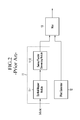
- FIG. 2 is a configuration diagram of a transmitter in a general MIMO system.
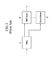
- FIG. 3 is a configuration diagram of a receiver in a general MIMO system.
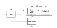
- FIG. 4 is a configuration diagram of a decoder in a MIMO system according to an exemplary embodiment of the present invention.
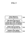
- FIG. 5 is a flowchart of a poly-diagonalization method according to an exemplary embodiment of the present invention.
- FIG. 6 is a flowchart for finding a soft decision value for each bit according to an exemplary embodiment of the present invention.
- the word “comprising” and variations such as “comprises” will be understood to imply the inclusion of stated elements but not the exclusion of any other elements.
- the terms “unit”, “device”, and “module” in the present specification represent a unit for processing a predetermined function or operation, which can be realized by hardware, software, or a combination of hardware and software.
- a mobile station may indicate a terminal, a mobile terminal (MT), a subscriber station (SS), a portable subscriber station (PSS), user equipment (UE), and an access terminal (AT), and may include entire or partial functions of the terminal, mobile terminal, subscriber station, portable subscriber station, and user equipment.
- a base station may indicate an access point (AP), a radio access station (RAS), a node B, a base transceiver station (BTS), and a mobile multihop relay (MMR)-BS, and may include entire or partial functions of the AP, RAS, node B, BTS, and MMR-BS.
- AP access point
- RAS radio access station
- BTS base transceiver station
- MMR mobile multihop relay
- FIG. 1 is a block diagram of a general MIMO system.
- the MIMO system includes a MIMO transmitter 10 , a MIMO channel 20 , and a MIMO receiver 30 .
- the MIMO channel 20 is an effective channel including a baseband postprocessor of the MIMO transmitter 10 , an IF/RF processor, a multiple antenna channel, an RF/IF processor of a receiving part, and a baseband preprocessor, and is generally denoted as an N ⁇ M single complex matrix H.
- M is the number of transmit antennas and N is the number of receive antennas, and the input/output of the MIMO channel 20 is defined below.
- s(t) a transmission symbol vector (M ⁇ 1 vector) at the t-th time
- y(t) a receiving symbol vector (N ⁇ 1 vector) at the t-th time
- G a MIMO channel matrix (N ⁇ M matrix)
- the E[•] is an expectation value.
- a configuration of the MIMO transmitter 10 will now be described with reference to FIG. 2 .
- FIG. 2 is a configuration diagram of a transmitter in a general MIMO system.
- the MIMO transmitter 10 includes a data vector generator 11 , a pilot generator 12 , and a multiplexer 13 .
- the data vector generator 11 includes a symbol mapper module 11 - 1 and a series/parallel converting module 11 - 2 , and the data vector generated by the data vector generator 11 and the pilot vector generated by the pilot generator 12 are multiplexed by the multiplexer 13 .
- the pilot vector is known by the MIMO transmitter 10 and the MIMO receiver 30 , and is used for channel estimation by the MIMO receiver 30 .
- the data vector is information data generated by input information.
- the data vector and the pilot vector are (M ⁇ 1) complex vectors, and the real part and the imaginary part thereof correspond to the in-phase component and the quadrature-phase of the digital modulator.
- a s is a symbol set for the symbol s having 2 m elements.
- the data vector s including M symbols is processed as a block in the MIMO system, and a data vector s includes mM information bits since each symbol has m bits.
- the MIMO receiver 30 of FIG. 1 will be described with reference to FIG. 3 .
- FIG. 3 is a configuration diagram of a receiver in a general MIMO system.
- the MIMO receiver 30 includes a demultiplexer 31 , a MIMO decoder 32 , and a channel estimator 33 .
- the demultiplexer 31 switches the (N ⁇ 1) channel input vector r input by the MIMO channel 20 at a predetermined time to transmit the channel input corresponding to a pilot to the channel estimator 33 and the channel input corresponding to data symbol vector to the MIMO decoder 32 .
- the predetermined time represents the time when the demultiplexer 31 has received the symbol including the pilot from the transmitter.
- the channel estimator 33 estimates a channel matrix from the channel input vector transmitted by the demultiplexer 31 , and transmits the estimated channel matrix H to the MIMO decoder 32 so as to use the same for data symbol decoding.
- a MIMO system for reducing the complexity of the receiving part and generating a great packet error rate (PER) performance will now be described in the exemplary embodiment of the present invention. That is, interference is partially eliminated and interference is partially allowed in the exemplary embodiment of the present invention, and hence a combined decoding process is performed in consideration of the allowed interference other than reducing the amplitude of noise power in the postprocess, which will be described in detail with reference to FIG. 4 .
- PER packet error rate
- s is a transmission symbol vector (M ⁇ 1 vector)
- y is a received symbol vector (N ⁇ 1 vector).
- FIG. 4 is a configuration diagram of a decoder in a MIMO system according to an exemplary embodiment of the present invention.
- the decoder includes a linear process module 210 and a decoding module 220 .
- the linear process module 210 multiplies the received signal vector y output by the demultiplexer 100 and the (M ⁇ N) poly-diagonalized matrix B that depends on the channel H estimated by the channel estimator 200 to generate a (M ⁇ 1) vector y′.
- the effect of poly-diagonalizing the equivalent channel is acquired by using the poly-diagonalized matrix B, and two methods for finding the M ⁇ N poly-diagonalized matrix B will be described in the exemplary embodiment of the present invention.
- the first method is poly-diagonalization based on the noise power amplification minimizing index
- the second one is poly-diagonalization based on the mutual information maximizing index, which will be described with reference to FIG. 5 .
- the decoding module 220 generates soft decision values for the respective bits included in the transmission symbol vector by using the received signal vector from which the interference output by the linear process module 210 is partially eliminated, a variance value of the sum of noise and interference, and a coefficient.
- a trellis decoding module toward the decoding module 220 is used in the exemplary embodiment of the present invention.
- the soft decision value generated by the decoding module 220 is used to decode the received signal that is input to the receiving part into a transmission signal.
- a method for poly-diagonalizing the received signal by using the decoder of the MIMO system will now be described with reference to FIG. 5 .
- Each calculation is illustrated to be sequentially performed in FIG. 5 , and parallel calculation is also possible.
- FIG. 5 is a flowchart of a poly-diagonalization method according to an exemplary embodiment of the present invention.
- a poly-diagonalized matrix is found from a channel matrix H for the received signal (S 100 ), and an effective signal component channel vector, an allowable interference component channel vector, and an interference component channel vector to be eliminated are defined from the channel matrix (S 110 ).
- a projection matrix P k and a specific column matrix b k of the poly-diagonalized matrix are calculated from the allowable interference component channel vector and the interference component channel vector to be eliminated (S 120 ), and a coefficient and a variance of the sum of noise and interference are calculated from the calculated specific column matrix b k and are then output (S 130 ).
- Equation 19 the matrix K k value (shown in Equation 19) that is an addition of a product of an allowable interference component channel vector and an interference component channel vector to be eliminated to a product of a variance and a unit matrix I, other than the projection matrix.
- the first method is the poly-diagonalization method based on the noise power amplification minimizing index
- the second one is the poly-diagonalization method based on the mutual information maximizing index.
- the (L+1)-th order poly-diagonalized matrix can be configured with (L+1) m ⁇ m diagonal matrixes.
- the (L+1)-th order poly-diagonalized matrix can be defined as the matrix E expressed in Equation 2.
- the rows and columns of the matrix E have (L+1) components other than 0.
- the poly-diagonalized matrix B for a random matrix H is defined by multiplying a Hermitian transpose of B and an estimate matrix H of the real channel matrix and controlling the multiplication result to be a poly-diagonalized format.
- B H is the Hermitian transpose of the matrix B
- l of D l is the l-th diagonal component.
- Equation 3 can be expressed by the k-th column b k of the poly-diagonalized matrix B and the k-th column h k of the estimate matrix of the channel matrix, as shown in Equation 4.
- (•)M represents a modulo-M process.
- the linear process module 210 multiplies the poly-diagonalized matrix B and a received signal vector y to generate a received signal vector from which interference is partially removed as expressed in Equation 5, and transmits the received signal vector to a trellis decoder, that is, the decoding module 220 .
- a trellis decoder that is, the decoding module 220 .
- the received signal vector from which interference is partially removed is obtained as expressed in Equation 6.
- y′ B H y (Equation 5)
- Equation 7 y′ k represents the k-th component of the poly-diagonalized received signal vector.
- the average of the noise component n′ k is 0, and the variance is E
- the soft decision values of the symbols s k can be generated with relatively simple hardware and less operation complexity.
- Equation 8 the additional constraint is used so as to maximize the signal-to-noise ratio (SNR) expressed in Equation 8.
- SNR k
- the channel matrix H is divided into 3 sub-matrixes.
- the 3 sub-matrixes are hk, ⁇ k , and H k respectively, and represent a channel vector of an effective signal component of b k , and sub-channel matrixes of an allowable interference component and an interference component to be eliminated.
- the 3 sub-matrixes satisfy the condition of Equation 10.
- HH H h k h k H + ⁇ k ⁇ k H H k H k H [Equation 10]
- Equation 11 The projection matrix P k of b k is defined as expressed in Equation 11, and projects a vector into the vector space configured by the column vector of H k .
- P k H k ( H k H H k ) ⁇ 1 H k H [Equation 11]
- Equation 13 The solution of Equation 12 for a random complex constant c k is expressed in Equation 13.
- 2 ] c k
- 2 h k H ( I ⁇ P k )( I ⁇ P k ) h k k 0,1,2 , . . . ,M ⁇ 1 [Equation 15]
- the poly-diagonalization method based on the noise power amplification minimizing index has been described from among the methods for finding the poly-diagonalized matrix, and the second poly-diagonalization method according to the mutual information maximizing index will now be described.
- the poly-diagonalization method according to the mutual information maximizing index indicates a pseudo poly-diagonalization method.
- the 3 sub-matrixes satisfy the condition of Equation 10.
- the data symbol vector s is also divided into 3 components. That is, s is divided into s k , ⁇ k , and s k , which respectively represent a data symbol of an effective signal component, a data symbol vector of an (L ⁇ 1) allowable interference component, and a data symbol vector of an (M ⁇ L ⁇ 1) ⁇ 1 interference component to be eliminated.
- Equation 17 is given when the k-th column vector of the poly-diagonalized matrix B is set to be b k and Equation 16 is rewritten for the respective components.
- the k-th column vector b k of the pseudo poly-diagonalized matrix B is defined as the solution of the optimization problem of Equation 20.
- Equation 21 The solution of Equation 20 is given as Equation 21 for a random complex constant c k .
- Equation 21 The solution given as Equation 21 approaches the solution of Equation 13 as the background noise power ⁇ 2 becomes 0 ( ⁇ 2 ⁇ 0).
- the respective coefficients of Equation 17 can be expressed as Equation 22 by using Equation 21, and the variance of the sum of noise and the interference to be removed is expressed as Equation 23.
- the received signal vector y′ from which interference is partially removed, the coefficient value, and the variance of the sum of noise and interference are input to the trellis decode module and are used for finding the soft decision values of the respective transmission bits.
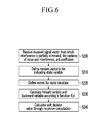
- a method for finding a soft decision value for each bit by using the tail-biting trellis will now be described with reference to FIG. 6 .
- FIG. 6 is a flowchart for finding a soft decision value for each bit according to an exemplary embodiment of the present invention.
- the decoding module 220 defines a random vector tk for indicating a state variable of the transmission symbol vector s (S 210 ), and defines a metric for a state transition (S 220 ).
- the decoding module 220 calculates a forward variable and a backward variable according to the function f(x) included in the metric (S 230 ), and calculates the soft decision value L j for each bit included in the transmission symbol vector s of the received signal (S 240 ) by performing a recursive operation on the forward variable and the backward variable.
- the above-described trellis decoding method is well known to a person skilled in the art.
- the decoding module 220 according to the exemplary embodiment of the present invention performs the decoding process by using the linear preprocess result of the linear process module 210 , and hence the tail-biting trellis decode that is a trellis decoding method will be described.
- a trellis is expressed by a node for indicating a specific state at a level and a branch for indicating a specific state transition.
- Equation 25 can be defined in the case of t k ⁇ 1 .
- t k,j t (k ⁇ 1),(j ⁇ 1) [Equation 26]
- a set of all state vector pairs (t,t′) for satisfying the condition of Equation 26 that the random vector pair (t k ,t (k ⁇ 1) m ) may have will be defined as T.
- Equation 27 the metric ⁇ k (t,t′) for the state transition (t,t′) in the k-th trellis stage is defined as Equation 27.
- f(x) is a monotonic decrement or increment function for the variable x.
- ⁇ ′ k , a kl and ⁇ k 2 can be calculated by Equation 7, Equation 14, and Equation 25 when they are linked with the linear process module 210 that follows the poly-diagonalization method based on the noise power amplification minimizing index from among the poly-diagonalization methods described with reference to FIG. 5 .
- the same can be calculated by Equation 17, Equation 22, and Equation 23 when they follow the poly-diagonalization method according to the mutual information maximizing index.
- a forward variable ⁇ k (t) and a backward variable ⁇ k (t) are defined with the metric that is related to the state of each trellis state.
- the variables are reset with a predetermined value, and a recursive computation is performed thereon to acquire desired values.
- the recursive computation is changed depending on whether the function f(x) of Equation 27 is a monotonic decrement function or a monotonic increment function for x.
- Equation 28 and Equation 29 are given, and when it is a monotonic increment function, Equation 30 and Equation 31 are given.
- a is a constant.
- the soft decision values L j are used to decode the received signal that is input to the receiving part into a transmission signal.
- the above-described embodiments can be realized through a program for realizing functions corresponding to the configuration of the embodiments or a recording medium for recording the program in addition to through the above-described device and/or method, which is easily realized by a person skilled in the art.
Landscapes
- Engineering & Computer Science (AREA)
- Computer Networks & Wireless Communication (AREA)
- Signal Processing (AREA)
- Radio Transmission System (AREA)
Abstract
Description
y=Gs+n (Equation 1)
y′=B H y (Equation 5)
y′=B H Hs+B H n=Es+B H n (Equation 6)
SNRk ≡|b k H h k|2 /|b k H b k|2 (Equation 8)
HH H =h k h k H +Ĥ k Ĥ k H
P k =
b k =c k(I−P k)h k k=0,1,2, . . . ,M−1 [Equation 13]
a kl =c k h k H(I−P k)h (k−l)
σk 2 ≡E[|n′ k|2 ]=c k|2 h k H(I−P k)(I−P k)h k k=0,1,2, . . . ,M−1 [Equation 15]
y′=B H y [Equation 16]
a kl =b k H h (k−l)
K k =
b k =c k K k −1 h k k=0,1,2, . . . ,M−1 [Equation 21]
The solution given as Equation 21 approaches the solution of
a kl =c k h k H K k −1 h (k−l)
σk 2 =E[|n′ k|2 ]=c k|2 h k H K k −1 h k k=0,1,2, . . . ,M−1 [Equation 23]
t k =[t k,0 ,t k,1 , . . . ,t k,L−1]T ≡[s (k)
t (k−1)
t k,j =t (k−1),(j−1) [Equation 26]
Claims (15)
Applications Claiming Priority (5)
| Application Number | Priority Date | Filing Date | Title |
|---|---|---|---|
| KR10-2007-0053208 | 2007-05-31 | ||
| KR20070053208 | 2007-05-31 | ||
| KR1020070093558A KR100932260B1 (en) | 2007-05-31 | 2007-09-14 | Decoding device and method for multiple input multiple output system |
| KR10-2007-0093558 | 2007-09-14 | ||
| PCT/KR2008/002790 WO2008147067A1 (en) | 2007-05-31 | 2008-05-19 | Decoding device and method for mimo system |
Publications (2)
| Publication Number | Publication Date |
|---|---|
| US20100189200A1 US20100189200A1 (en) | 2010-07-29 |
| US8265204B2 true US8265204B2 (en) | 2012-09-11 |
Family
ID=40367147
Family Applications (1)
| Application Number | Title | Priority Date | Filing Date |
|---|---|---|---|
| US12/602,353 Expired - Fee Related US8265204B2 (en) | 2007-05-31 | 2008-05-19 | Decoding device and method for MIMO system |
Country Status (2)
| Country | Link |
|---|---|
| US (1) | US8265204B2 (en) |
| KR (1) | KR100932260B1 (en) |
Families Citing this family (4)
| Publication number | Priority date | Publication date | Assignee | Title |
|---|---|---|---|---|
| CN101834651B (en) * | 2010-02-08 | 2013-01-09 | 上海交通大学 | Data information linear preprocessing method of multiuser multiple data stream MIMO (Multiple Input Multiple Output) system |
| KR101198396B1 (en) | 2010-05-27 | 2012-11-09 | 단국대학교 산학협력단 | Decoder and decoding method for multiple input multiple output system |
| US8594215B2 (en) * | 2010-06-11 | 2013-11-26 | Alcatel Lucent | MIMO system having a plurality of service antennas for data transmission thereof |
| US9509381B1 (en) * | 2015-09-18 | 2016-11-29 | Samsung Electronics Co., Ltd | Apparatus and method of blind detection of interference rank information in wireless communication system |
Citations (24)
| Publication number | Priority date | Publication date | Assignee | Title |
|---|---|---|---|---|
| US5867531A (en) * | 1995-03-09 | 1999-02-02 | Oki Electric Industry Co., Ltd. | Maximum likelihood sequence estimator and maximum likelihood sequence estimating method |
| WO2000013386A1 (en) | 1998-08-31 | 2000-03-09 | Ericsson, Inc. | Coherent demodulation and sequence estimation for differential psk signals |
| WO2000025447A2 (en) | 1998-10-28 | 2000-05-04 | Ericsson, Inc. | Diversity receiver for radio communications |
| US20030179733A1 (en) | 2002-03-22 | 2003-09-25 | Motomitsu Yano | CDM receiver apparatus and rake synthesizer apparatus |
| US20040001564A1 (en) | 2002-06-24 | 2004-01-01 | Albert Chan | Reduced complexity receiver for space-time- bit-interleaved coded modulation |
| US20040052315A1 (en) * | 2000-10-03 | 2004-03-18 | Jorn Thielecke | Multi strata system |
| WO2004064298A2 (en) | 2003-01-10 | 2004-07-29 | Interdigital Technology Corporation | Generalized two-stage data estimation |
| US20040170233A1 (en) * | 2003-02-27 | 2004-09-02 | Onggosanusi Eko N. | Symbol normalization in MIMO systems |
| US20050271121A1 (en) * | 2003-08-05 | 2005-12-08 | Stmicroelectronics S.R.L. | Method for transmitting signals using antenna diversity, for instance in mobile communication systems, transmitter, receiver and computer program product therefor |
| KR20070010139A (en) | 2004-05-10 | 2007-01-22 | 소니 가부시끼 가이샤 | Wireless communication systems, wireless communication devices and wireless communication methods, and computer programs |
| KR20070039285A (en) | 2005-10-07 | 2007-04-11 | 삼성전자주식회사 | Signal detection method and apparatus in multi-input / output communication system |
| US20070253479A1 (en) * | 2006-04-30 | 2007-11-01 | Debargha Mukherjee | Robust and efficient compression/decompression providing for adjustable division of computational complexity between encoding/compression and decoding/decompression |
| US20080092025A1 (en) * | 2006-10-13 | 2008-04-17 | Navini Networks, Inc. | Method and System for Improving Decoding Efficiency in Wireless Receivers |
| US7369511B2 (en) * | 2004-01-09 | 2008-05-06 | Kabushiki Kaisha Toshiba | Communication method, communication apparatus, and communication system |
| US7620114B2 (en) | 2004-05-10 | 2009-11-17 | Sony Corporation | System, method, apparatus, and computer program for wireless communication |
| US20100104039A1 (en) * | 2001-05-17 | 2010-04-29 | Qualcomm Incorporated | Method and apparatus for processing data for transmission in a multi-channel communication system using selective channel inversion |
| US20100195630A1 (en) * | 2004-06-18 | 2010-08-05 | Qualcomm Incorporated | Quasi-orthogonal multiplexing for a multi-carrier communication system |
| US20100215115A1 (en) * | 2003-10-08 | 2010-08-26 | Qualcomm Incorporated | Receiver spatial processing for eigenmode transmission in a mimo system |
| US7876839B2 (en) * | 2005-12-30 | 2011-01-25 | Intel Corporation | Receiver and method for channel estimation for multicarrier communication systems |
| US7881247B2 (en) * | 2006-08-17 | 2011-02-01 | Interdigital Technology Corporation | Method and apparatus for providing efficient precoding feedback in a MIMO wireless communication system |
| US7907912B2 (en) * | 2005-11-17 | 2011-03-15 | Samsung Electronics Co., Ltd | Apparatus and method for eliminating multi-user interference |
| US8014267B2 (en) * | 2003-06-30 | 2011-09-06 | Agere Systems Inc. | Methods and apparatus for backwards compatible communication in a multiple input multiple output communication system with lower order receivers |
| US8031762B2 (en) * | 2008-08-04 | 2011-10-04 | Redpine Signals, Inc. | Stream weight estimation and compensation in SIMO/MIMO OFDM receivers |
| US20110243284A1 (en) * | 2005-01-28 | 2011-10-06 | At&T Intellectual Property I, L.P. | Delay Restricted Channel Estimation for Multi-Carrier Systems |
-
2007
- 2007-09-14 KR KR1020070093558A patent/KR100932260B1/en not_active Expired - Fee Related
-
2008
- 2008-05-19 US US12/602,353 patent/US8265204B2/en not_active Expired - Fee Related
Patent Citations (26)
| Publication number | Priority date | Publication date | Assignee | Title |
|---|---|---|---|---|
| US5867531A (en) * | 1995-03-09 | 1999-02-02 | Oki Electric Industry Co., Ltd. | Maximum likelihood sequence estimator and maximum likelihood sequence estimating method |
| WO2000013386A1 (en) | 1998-08-31 | 2000-03-09 | Ericsson, Inc. | Coherent demodulation and sequence estimation for differential psk signals |
| WO2000025447A2 (en) | 1998-10-28 | 2000-05-04 | Ericsson, Inc. | Diversity receiver for radio communications |
| US20040052315A1 (en) * | 2000-10-03 | 2004-03-18 | Jorn Thielecke | Multi strata system |
| US20100104039A1 (en) * | 2001-05-17 | 2010-04-29 | Qualcomm Incorporated | Method and apparatus for processing data for transmission in a multi-channel communication system using selective channel inversion |
| US20030179733A1 (en) | 2002-03-22 | 2003-09-25 | Motomitsu Yano | CDM receiver apparatus and rake synthesizer apparatus |
| US20040001564A1 (en) | 2002-06-24 | 2004-01-01 | Albert Chan | Reduced complexity receiver for space-time- bit-interleaved coded modulation |
| WO2004064298A2 (en) | 2003-01-10 | 2004-07-29 | Interdigital Technology Corporation | Generalized two-stage data estimation |
| US20040170233A1 (en) * | 2003-02-27 | 2004-09-02 | Onggosanusi Eko N. | Symbol normalization in MIMO systems |
| US8014267B2 (en) * | 2003-06-30 | 2011-09-06 | Agere Systems Inc. | Methods and apparatus for backwards compatible communication in a multiple input multiple output communication system with lower order receivers |
| US20050271121A1 (en) * | 2003-08-05 | 2005-12-08 | Stmicroelectronics S.R.L. | Method for transmitting signals using antenna diversity, for instance in mobile communication systems, transmitter, receiver and computer program product therefor |
| US7460581B2 (en) * | 2003-08-05 | 2008-12-02 | Stmicroelectronics S.R.L. | Method for transmitting signals using antenna diversity, for instance in mobile communication systems, transmitter, receiver and computer program product therefor |
| US20100215115A1 (en) * | 2003-10-08 | 2010-08-26 | Qualcomm Incorporated | Receiver spatial processing for eigenmode transmission in a mimo system |
| US7369511B2 (en) * | 2004-01-09 | 2008-05-06 | Kabushiki Kaisha Toshiba | Communication method, communication apparatus, and communication system |
| KR20070010139A (en) | 2004-05-10 | 2007-01-22 | 소니 가부시끼 가이샤 | Wireless communication systems, wireless communication devices and wireless communication methods, and computer programs |
| US7620114B2 (en) | 2004-05-10 | 2009-11-17 | Sony Corporation | System, method, apparatus, and computer program for wireless communication |
| US20100195630A1 (en) * | 2004-06-18 | 2010-08-05 | Qualcomm Incorporated | Quasi-orthogonal multiplexing for a multi-carrier communication system |
| US20110243284A1 (en) * | 2005-01-28 | 2011-10-06 | At&T Intellectual Property I, L.P. | Delay Restricted Channel Estimation for Multi-Carrier Systems |
| US20070086549A1 (en) | 2005-10-07 | 2007-04-19 | Samsung Electronics Co., Ltd. | Method and apparatus for detecting signal in a MIMO communication system |
| KR20070039285A (en) | 2005-10-07 | 2007-04-11 | 삼성전자주식회사 | Signal detection method and apparatus in multi-input / output communication system |
| US7907912B2 (en) * | 2005-11-17 | 2011-03-15 | Samsung Electronics Co., Ltd | Apparatus and method for eliminating multi-user interference |
| US7876839B2 (en) * | 2005-12-30 | 2011-01-25 | Intel Corporation | Receiver and method for channel estimation for multicarrier communication systems |
| US20070253479A1 (en) * | 2006-04-30 | 2007-11-01 | Debargha Mukherjee | Robust and efficient compression/decompression providing for adjustable division of computational complexity between encoding/compression and decoding/decompression |
| US7881247B2 (en) * | 2006-08-17 | 2011-02-01 | Interdigital Technology Corporation | Method and apparatus for providing efficient precoding feedback in a MIMO wireless communication system |
| US20080092025A1 (en) * | 2006-10-13 | 2008-04-17 | Navini Networks, Inc. | Method and System for Improving Decoding Efficiency in Wireless Receivers |
| US8031762B2 (en) * | 2008-08-04 | 2011-10-04 | Redpine Signals, Inc. | Stream weight estimation and compensation in SIMO/MIMO OFDM receivers |
Non-Patent Citations (2)
| Title |
|---|
| Seokhyun Yoon, et al., "A Detection Algorithm for Multi-Input Multi-Output (MIMO) Transmission using Poly-Diagonalization and Trellis Decoding," Proc. of Wireless Communications and Networking Conference (WCNC), Mar. 31, 2008. |
| Wen Jiang, et al., "Bi-Truncation for Simplified MIMO Signal Detection," Globecome 2004, vol. 1, Nov. 29-Dec. 3, 2004, pp. 401-405. |
Also Published As
| Publication number | Publication date |
|---|---|
| US20100189200A1 (en) | 2010-07-29 |
| KR20080105953A (en) | 2008-12-04 |
| KR100932260B1 (en) | 2009-12-16 |
Similar Documents
| Publication | Publication Date | Title |
|---|---|---|
| US8077788B2 (en) | Soft demapping for MIMO decoding | |
| US6901122B2 (en) | Method and apparatus for restoring a soft decision component of a signal | |
| CN101958764B (en) | Transmitting device, signal generating apparatus and transmitting method | |
| US20110176633A1 (en) | Method and system for orthogonalized beamforming in multiple user multiple input multiple output (mu-mimo) communication systems | |
| US11489557B2 (en) | Wireless communication system, wireless communication method, transmitting station device and receiving station device | |
| US9634879B2 (en) | Demodulator apparatus and demodulation method | |
| US8135101B2 (en) | Data equalisation in a communication receiver wth transmit and receive diversity | |
| US8811215B2 (en) | Apparatus and method for detecting signal in spatial multiplexing system | |
| US7342970B2 (en) | Array processing using an aggregate channel matrix generated using a block code structure | |
| US7986919B2 (en) | Simplified impairments matrix calculation for SINR estimation | |
| US20030186650A1 (en) | Closed loop multiple antenna system | |
| US20090296863A1 (en) | Interference Estimator | |
| US20100265853A1 (en) | Beamforming method using multiple antennas | |
| JP4381901B2 (en) | Channel estimation and data detection method | |
| US8265204B2 (en) | Decoding device and method for MIMO system | |
| US7835458B2 (en) | Method of decoding a spatially multiplexed signal and its corresponding receiver | |
| CN102246439A (en) | SNIR estimation in HSPA implementing MIMO | |
| US11646772B2 (en) | Wireless communication system, wireless communication method, transmitting station device and receiving station device | |
| US8885454B2 (en) | Apparatus and method for precoding using channel orthogonalization in multi-user multi-antenna system | |
| WO2007114478A1 (en) | Receiver | |
| US20060140300A1 (en) | Wireless communication device | |
| WO2008147067A1 (en) | Decoding device and method for mimo system | |
| Leroux et al. | The performance of soft macrodiversity based on maximal-ratio combining in uncorrelated Rician fading | |
| KR101397347B1 (en) | A method for generating soft decision information in mimo system | |
| DUNNA | Near-Optimal Channel Estimation in Fast Fading Spatially Modulated Links |
Legal Events
| Date | Code | Title | Description |
|---|---|---|---|
| AS | Assignment |
Owner name: ELECTRONICS AND TELECOMMUNICATIONS RESEARCH INSTIT Free format text: ASSIGNMENT OF ASSIGNORS INTEREST;ASSIGNORS:CHOI, EUN-YOUNG;YOON, CHAN HO;SON, JUNG BO;AND OTHERS;SIGNING DATES FROM 20091111 TO 20091117;REEL/FRAME:023587/0102 |
|
| STCF | Information on status: patent grant |
Free format text: PATENTED CASE |
|
| FEPP | Fee payment procedure |
Free format text: PAYOR NUMBER ASSIGNED (ORIGINAL EVENT CODE: ASPN); ENTITY STATUS OF PATENT OWNER: SMALL ENTITY |
|
| FPAY | Fee payment |
Year of fee payment: 4 |
|
| FEPP | Fee payment procedure |
Free format text: MAINTENANCE FEE REMINDER MAILED (ORIGINAL EVENT CODE: REM.); ENTITY STATUS OF PATENT OWNER: SMALL ENTITY |
|
| LAPS | Lapse for failure to pay maintenance fees |
Free format text: PATENT EXPIRED FOR FAILURE TO PAY MAINTENANCE FEES (ORIGINAL EVENT CODE: EXP.); ENTITY STATUS OF PATENT OWNER: SMALL ENTITY |
|
| STCH | Information on status: patent discontinuation |
Free format text: PATENT EXPIRED DUE TO NONPAYMENT OF MAINTENANCE FEES UNDER 37 CFR 1.362 |
|
| FP | Lapsed due to failure to pay maintenance fee |
Effective date: 20200911 |