US8256726B2 - Head for video-photographic apparatus - Google Patents
Head for video-photographic apparatus Download PDFInfo
- Publication number
- US8256726B2 US8256726B2 US12/835,844 US83584410A US8256726B2 US 8256726 B2 US8256726 B2 US 8256726B2 US 83584410 A US83584410 A US 83584410A US 8256726 B2 US8256726 B2 US 8256726B2
- Authority
- US
- United States
- Prior art keywords
- slide
- platform
- support head
- head according
- signal
- Prior art date
- Legal status (The legal status is an assumption and is not a legal conclusion. Google has not performed a legal analysis and makes no representation as to the accuracy of the status listed.)
- Active, expires
Links
- 230000002596 correlated effect Effects 0.000 claims abstract description 4
- 230000003287 optical effect Effects 0.000 claims description 15
- 230000011664 signaling Effects 0.000 claims description 14
- 230000001419 dependent effect Effects 0.000 claims description 5
- 230000005484 gravity Effects 0.000 description 3
- 230000008901 benefit Effects 0.000 description 2
- 230000000875 corresponding effect Effects 0.000 description 2
- 230000005672 electromagnetic field Effects 0.000 description 2
- 238000012986 modification Methods 0.000 description 2
- 230000004048 modification Effects 0.000 description 2
- 239000000853 adhesive Substances 0.000 description 1
- 230000001070 adhesive effect Effects 0.000 description 1
- 230000000712 assembly Effects 0.000 description 1
- 238000000429 assembly Methods 0.000 description 1
- 238000001514 detection method Methods 0.000 description 1
- 238000006073 displacement reaction Methods 0.000 description 1
- 230000000694 effects Effects 0.000 description 1
- 238000009877 rendering Methods 0.000 description 1
Images


Classifications
-
- F—MECHANICAL ENGINEERING; LIGHTING; HEATING; WEAPONS; BLASTING
- F16—ENGINEERING ELEMENTS AND UNITS; GENERAL MEASURES FOR PRODUCING AND MAINTAINING EFFECTIVE FUNCTIONING OF MACHINES OR INSTALLATIONS; THERMAL INSULATION IN GENERAL
- F16M—FRAMES, CASINGS OR BEDS OF ENGINES, MACHINES OR APPARATUS, NOT SPECIFIC TO ENGINES, MACHINES OR APPARATUS PROVIDED FOR ELSEWHERE; STANDS; SUPPORTS
- F16M1/00—Frames or casings of engines, machines or apparatus; Frames serving as machinery beds
- F16M1/04—Frames or casings of engines, machines or apparatus; Frames serving as machinery beds for rotary engines or similar machines
-
- F—MECHANICAL ENGINEERING; LIGHTING; HEATING; WEAPONS; BLASTING
- F16—ENGINEERING ELEMENTS AND UNITS; GENERAL MEASURES FOR PRODUCING AND MAINTAINING EFFECTIVE FUNCTIONING OF MACHINES OR INSTALLATIONS; THERMAL INSULATION IN GENERAL
- F16M—FRAMES, CASINGS OR BEDS OF ENGINES, MACHINES OR APPARATUS, NOT SPECIFIC TO ENGINES, MACHINES OR APPARATUS PROVIDED FOR ELSEWHERE; STANDS; SUPPORTS
- F16M11/00—Stands or trestles as supports for apparatus or articles placed thereon ; Stands for scientific apparatus such as gravitational force meters
- F16M11/02—Heads
- F16M11/04—Means for attachment of apparatus; Means allowing adjustment of the apparatus relatively to the stand
- F16M11/041—Allowing quick release of the apparatus
-
- F—MECHANICAL ENGINEERING; LIGHTING; HEATING; WEAPONS; BLASTING
- F16—ENGINEERING ELEMENTS AND UNITS; GENERAL MEASURES FOR PRODUCING AND MAINTAINING EFFECTIVE FUNCTIONING OF MACHINES OR INSTALLATIONS; THERMAL INSULATION IN GENERAL
- F16M—FRAMES, CASINGS OR BEDS OF ENGINES, MACHINES OR APPARATUS, NOT SPECIFIC TO ENGINES, MACHINES OR APPARATUS PROVIDED FOR ELSEWHERE; STANDS; SUPPORTS
- F16M11/00—Stands or trestles as supports for apparatus or articles placed thereon ; Stands for scientific apparatus such as gravitational force meters
- F16M11/02—Heads
- F16M11/04—Means for attachment of apparatus; Means allowing adjustment of the apparatus relatively to the stand
- F16M11/043—Allowing translations
-
- F—MECHANICAL ENGINEERING; LIGHTING; HEATING; WEAPONS; BLASTING
- F16—ENGINEERING ELEMENTS AND UNITS; GENERAL MEASURES FOR PRODUCING AND MAINTAINING EFFECTIVE FUNCTIONING OF MACHINES OR INSTALLATIONS; THERMAL INSULATION IN GENERAL
- F16M—FRAMES, CASINGS OR BEDS OF ENGINES, MACHINES OR APPARATUS, NOT SPECIFIC TO ENGINES, MACHINES OR APPARATUS PROVIDED FOR ELSEWHERE; STANDS; SUPPORTS
- F16M11/00—Stands or trestles as supports for apparatus or articles placed thereon ; Stands for scientific apparatus such as gravitational force meters
- F16M11/20—Undercarriages with or without wheels
- F16M11/2007—Undercarriages with or without wheels comprising means allowing pivoting adjustment
- F16M11/2021—Undercarriages with or without wheels comprising means allowing pivoting adjustment around a horizontal axis
-
- G—PHYSICS
- G03—PHOTOGRAPHY; CINEMATOGRAPHY; ANALOGOUS TECHNIQUES USING WAVES OTHER THAN OPTICAL WAVES; ELECTROGRAPHY; HOLOGRAPHY
- G03B—APPARATUS OR ARRANGEMENTS FOR TAKING PHOTOGRAPHS OR FOR PROJECTING OR VIEWING THEM; APPARATUS OR ARRANGEMENTS EMPLOYING ANALOGOUS TECHNIQUES USING WAVES OTHER THAN OPTICAL WAVES; ACCESSORIES THEREFOR
- G03B17/00—Details of cameras or camera bodies; Accessories therefor
- G03B17/56—Accessories
- G03B17/561—Support related camera accessories
-
- F—MECHANICAL ENGINEERING; LIGHTING; HEATING; WEAPONS; BLASTING
- F16—ENGINEERING ELEMENTS AND UNITS; GENERAL MEASURES FOR PRODUCING AND MAINTAINING EFFECTIVE FUNCTIONING OF MACHINES OR INSTALLATIONS; THERMAL INSULATION IN GENERAL
- F16M—FRAMES, CASINGS OR BEDS OF ENGINES, MACHINES OR APPARATUS, NOT SPECIFIC TO ENGINES, MACHINES OR APPARATUS PROVIDED FOR ELSEWHERE; STANDS; SUPPORTS
- F16M2200/00—Details of stands or supports
- F16M2200/02—Locking means
- F16M2200/025—Locking means for translational movement
Definitions
- the present invention relates to a support head for video-photographic apparatuses.
- support heads provided with a base which is fixed, in use, to a support structure, for example a tripod, with a platform fixed rotatably to the base about at least one axis of rotation, and with a plate, movable with respect to the platform, to which the video-photographic apparatuses are removably attached.
- the plate is provided with attaching means, mostly screw-type, by means of which the apparatus is attached to the plate.
- the apparatuses are positioned on the head and then moved during use in order to take the shots.
- the apparatus/head/tripod assembly must be stable, so as to avoid the operator having to support it, while taking the shots, in order to prevent it from rocking or tipping.
- the apparatus is attached, via the attaching means, to the plate, and the latter is positioned along the platform in a position in which the aforesaid assembly is stable.
- the apparatus Since it is not possible to attach/detach the apparatus from the plate without removing it from the head, the apparatus is kept attached to the plate and the latter is separated from the platform after use. Therefore, for subsequent use, the positioning operation described above must be repeated, that is, the operator must position the plate bearing the apparatus on the platform and move it to a position in which the apparatus/head/support assembly is balanced.
- the principal aim of the present invention is to provide a support head structurally and functionally designed to remedy the drawbacks mentioned with reference to the prior art cited.
- one aim of the invention is to provide a head configured in such a way as to facilitate the operations of positioning and balancing a video-photographic apparatus on the head itself.
- Another aim is to simplify the correct positioning of video-photographic apparatuses on a support head.
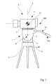
- FIG. 1 is a schematic lateral view of a support head produced according to the present invention and provided with a video camera;
- FIGS. 2 and 3 are two partial perspective views of the head of FIG. 1 from two different sides.
- FIG. 1 shows a support head 1 for video-photographic apparatuses, produced according to the present invention and comprising a base 3 on which a platform 2 is articulated so as to rotate about an axis of rotation X.
- the head 1 further comprises a control lever 14 fixed to the platform 2 , which projects outwards from the latter and is suitable for facilitating the rotational movement of the platform 2 about the axis of rotation X.
- the control lever 14 comprises a handgrip portion 14 a suitable for being gripped by a user in order to orientate the platform 2 .
- the base 3 of the head 1 is arranged to be fastened, in such a way as to be rotatable about the vertical axis Z, to a support structure to be placed on the ground in order to take video-photographic shots, such as, for example, a tripod 4 (illustrated only schematically in FIG. 1 ).
- the head 1 further comprises a slide 5 to which can be removably attached, via respective attaching means 6 , a video-photographic apparatus, for example a video camera 7 , shown in FIG. 1 .
- the slide 5 may be associated, in use, with the platform 2 , as explained more clearly hereinafter.
- sliding guides 8 On a base portion 2 a of the platform 2 are defined sliding guides 8 , extending in a positioning direction Y, and suitable for slidably receiving the slide 5 in such a way that it can be positioned in various operating positions on the platform 2 .
- the positioning direction Y is substantially perpendicular to the axis of rotation X.
- the axis of rotation X is generally horizontal in order to permit the “tilt” movement of the video camera 7 , though the present invention is in any case applicable to a support head comprising a platform pivotable about an axis oriented in any direction.
- the head 1 further comprises a locking device 9 for locking the slide 5 on the platform 2 in a desired position and preventing unwanted movements of the slide 5 and, therefore, of the video camera 7 attached thereto, while the head 1 is in use.
- the locking device 9 comprises a screw 10 extending in a threaded seat defined within the base portion 2 a of the platform 2 , in a transverse direction X 1 with respect to the positioning direction Y of the slide 5 .
- the direction X 1 is preferably perpendicular to the positioning direction Y and substantially parallel to the axis of rotation X.
- the screw 10 is provided at its opposed ends 10 a , 10 b , respectively with a locking block 11 suitable for interacting with a wall portion of the slide 5 to lock the latter in a desired position on the platform 2 , and with a head portion 12 positioned on the base portion 2 a of the platform 2 in such a way as to be accessible to an operator, and suitable for being rotated by an operator to lock/unlock the slide 5 , as explained more clearly hereinafter.
- Rotating the head portion 12 causes rotation of the screw 10 in the threaded seat and consequent displacement thereof, and of the block 11 fixed thereto, in the direction X 1 , respectively towards/away from the slide 5 .
- the head 1 further comprises a positioning system 20 , shown in FIG. 3 and suitable for facilitating the positioning, on the platform 2 , of the assembly, indicated as a whole by 100 in the drawings, formed by the slide 5 and the video camera 7 attached thereto.
- a positioning system 20 shown in FIG. 3 and suitable for facilitating the positioning, on the platform 2 , of the assembly, indicated as a whole by 100 in the drawings, formed by the slide 5 and the video camera 7 attached thereto.
- the assembly 100 is positioned in a balanced position P, shown in FIG. 1 , in which, with the platform 2 in a horizontal position, the centre of gravity G of the assembly 100 is positioned along the vertical axis Z, that is, vertically above the axis of rotation X.
- the assembly 100 By shifting the centre of gravity G from said balanced position P, the assembly 100 would exert on the platform 2 and, therefore, on the tripod 4 , a moment increasing progressively with the distance between the centre of gravity G and the vertical axis Z and with the weight of the video camera 7 .
- the balanced position P depends on the dimensions and the configuration of the apparatus attached to the slide 5 ; in the case where a photographic camera is used, the balanced position P also depends on the lens used and on its extension with respect to the body of the photographic camera.
- the balanced position P further depends on the position of the means for attaching the apparatus 6 with respect to the slide 5 and with respect to the body of the apparatus 7 .
- the positioning system 20 comprises generating means 22 for generating a variable signal, which are configured in such a way as to generate a signal which is monotonically variable along the positioning direction Y, the variable signal being correlated with a position of the slide 5 on the platform 2 , as explained more clearly hereinafter.
- the positioning system 20 further comprises detector means 21 , capable of detecting the variable signal generated by the generating means 22 for generating a variable signal.
- the signal generated by the generating means 22 varies monotonically along the positioning direction Y, there corresponds to each position of the slide 5 on the platform 2 a specific signal detected by the detector means 21 , and the detected signal is therefore correlated in a unique way with the position of the slide 5 on the platform 2 along the positioning direction Y, as explained more clearly hereinafter.
- the detector means 21 and the variable signal generating means 22 are preferably provided in a position in which they are substantially opposite one another.
- the generating means 22 for generating a variable signal are provided on the slide 5 and the detector means 21 are provided on the base portion 2 a of the platform 2 .
- the generating means 22 for generating a variable signal comprise a magnetic bar 24 positioned in the slide 5 and extending along the positioning direction Y, and the detector means 21 comprise an electromagnetic field detector 25 suitable for detecting the value of the magnetic field generated by the magnetic bar 24 .
- the bar 24 is oriented in such as way that by moving it along the positioning direction Y varies the intensity detected by the detector 25 of the magnetic field generated by the bar 24 .
- the bar 24 is positioned in such a way that its magnetic axis, ideally joining the south pole and the north pole of the bar 24 , is substantially parallel to the positioning direction Y.
- the intensity value of the magnetic field detected depends in a unique way on the position of the slide 5 with respect to the platform 2 .
- the generating means 22 for generating a variable signal may comprise any other element for generating a detected electromagnetic field which is variable along the positioning direction Y.
- the positioning system 20 further comprises a storing device 23 for storing a signal detected by the detector means 21 , that is, a specified position of the slide 5 on the platform 2 .
- the presence of the storing device 23 facilitates the subsequent positioning of the slide 5 on the platform 2 in the previously stored position, customarily the balanced position P, as explained more clearly hereinafter.
- the storing device 23 provided on the base portion 2 a of the platform 2 in a position such as to be accessible to an operator, may also act as a device for switching on the positioning system 20 .
- a switching on device separate from the storing device 23 may be provided.
- the positioning system 20 further comprises a processing device, not shown in the drawings, suitable for receiving the position signal detected by the detector means 21 and the signal stored by the storing device 23 , in order to compare the current position, that is, the position detected by the detector means 21 , with the position stored by the storing device 23 , that is, the balanced position P.
- the processing device may be positioned, for example, in the platform 2 .
- the processing device is also operatively connected to a signalling element 26 of the positioning system 20 which is suitable for emitting a warning signal to advise the operator of the approach of the slide 5 to a desired position on the platform 2 .
- the warning signal emitted by the signalling element 26 depends on the distance between the detected position and the stored position P, in such a way as to guide the operator when positioning the slide 5 on the platform 2 .
- the signalling element may comprise an optical signalling means, for example an indicator lamp 26 , as in the version shown in the drawings.
- the indicator lamp 26 may flash with a luminosity and/or flashing frequency which varies according to the distance between the detected position of the slide 5 and the stored position P thereof.
- the signalling element may comprise an acoustic signalling device suitable for emitting a sound whose frequency varies according to the distance between the detected position and the stored position P.
- the signalling element may emit a sound or light up only when the previously stored position is reached.
- the positioning system 20 comprises a display element operatively associated with the detector means 21 and with the storing device 23 and suitable for displaying the distance between the current detected position of the slide 5 and the previously stored position P.
- the operator reading the distance displayed on the display element, moves the slide 5 into the position in which a distance equal to “0” is displayed on the display element. This facilitates the positioning of the slide 5 on the platform 2 .
- the positioning system 20 further comprises a reference element, not shown in the drawings, suitable for detecting the presence of the slide 5 in the sliding guides 8 of the platform 2 and, consequently, permitting the functioning of the positioning system 20 , in the manner explained hereinafter.
- the reference element may comprise a pin or another mechanical reference element movable in the presence of the slide 5 in the sliding guides 8 .
- the reference element comprises a further magnetic field detector positioned on the platform 2 and spaced apart from the detector 25 along the positioning direction Y by a distance having a desired length.
- the intensity of the magnetic field detected by the detector 25 has a value equal to “0”. However, the detector 25 detects a magnetic field intensity “0” also when the slide 5 is not on the platform 2 , that is, when the bar 24 is sufficiently far away from the detector 25 .
- the presence of the reference element makes it possible to distinguish the two aforesaid positions in which a magnetic field of intensity “0” is detected.
- both the detector 25 and the further detector detect a magnetic field intensity equal to “0”, but conversely, when the slide 5 is on the platform 2 , at least one of the detector 25 and the further detector detects a magnetic field having an intensity other than “0”.
- the further detector does not permit the functioning of the positioning system 20 , while in the second case permission is given and the detection of the corresponding position can be carried out and therefore the slide 5 can be positioned as desired.
- the generating means 22 for generating a variable signal may be of the optical type and the detector means 21 then comprise an optical detector.
- the generating means 22 for generating a variable signal may comprise a coloured strip whose colour varies monotonically along the positioning direction Y, or an optically readable code, that is, capable of being read by an optical reading device.
- the optically readable code may for example be a strip provided with a bar code having alternating dark and light bars whose thickness and/or spacing varies along the positioning direction Y, or a light bar with dark marks in specified zones thereof, or vice versa.
- optical reading devices are used which are suitable for recognising the optically readable codes used, for example a laser reading device, of the type used for optical reading, or a microvideo camera.
- the positioning system 20 may comprise a light source suitable for emitting a light signal towards the strip, which is capable of reflecting said light signal at least partially towards the detector means 21 , the latter comprising an optical detector for detecting the optical signal reflected by the strip and the light intensity of which depends on the section of the strip affected by the reflected optical signal.
- the reflected optical signal then depends on the position of the slide 5 on the platform 2 , therefore, in this case also, the detector means 21 detect a signal dependent in a unique way on the position of the slide 5 .
- the detector means 21 comprise a video camera which focuses on and shoots a particular portion of the coloured strip, or of the optically readable code, emitting or making available a signal dependent in a unique way on the position of the slide 5 on the platform 2 .
- the generating means 22 for generating a variable signal comprise an element with variable geometry having a dimension monotonically variable along the positioning direction Y, the detector means 21 comprising a device suitable for detecting the variation of the aforesaid dimension and, therefore, the position of the slide 5 on the platform 2 .
- the detector means 21 comprise a detector which sends a signal dependent on the distance between the portion of the element with variable geometry affected by said return signal and the detector means 21 .
- the element with variable geometry may comprise a groove provided in an edge portion of the slide 5 and which, in use, faces towards the detector means 21 , and is shaped in such a way that its depth, that is, the distance from the detector means 21 , varies monotonically along the positioning direction Y.
- an edge portion of the slide 5 may have a thickness which is monotonically variable along the positioning direction Y, the detector means 21 being such as to detect such a variation in thickness and to emit a corresponding position signal.
- the detector means 21 comprise a feeler element, for example a feeling wheel fixed to the platform 2 in a position such as to be rotated by frictional force by the edge of the slide 5 as a result of movement thereof.
- the detector means 21 further comprise a detector, for example a counter suitable for detecting the position of the wheel and therefore of the slide 5 in the platform 2 .
- the edge of the slide 5 may be provided with a plurality of alternating projections and recesses, the projections being suitable for engaging with suitable portions of the wheel in order to move it in rotation as a result of a movement of the slide 5 in the sliding guides 8 .
- a potentiometric wheel may be used.
- moving the slide 5 along the positioning direction Y causes rotation of the feeling wheel and therefore of the signal detected by the detecting means.
- the operator switches on the positioning system 20 and positions the slide 5 on the sliding guides 8 , thus actuating the reference element which permits the functioning of the positioning system 20 .
- This position is stored by means of the storing device 23 which, as stated, stores a particular signal detected by the detector means 21 .
- the operator separates the slide 5 from the platform 2 , replacing the various components in containers for transport.
- the operator switches on the positioning system 20 , positions the slide 5 on the sliding guides 8 , actuating the reference element, and moves the slide 5 until the previously stored position is reached, that is, the balanced position P, being guided in this operation by the signalling element 26 and/or the display element.
- the positioning of the apparatus in the balanced position P becomes simple and instantaneous.
- a lighting device may be provided, for example one or more luminous LEDs, suitable for illuminating the sliding guides in order to facilitate the position of the slide 5 on the guides 8 themselves.
- Such a lighting device is particularly useful, especially in the case of use at night or in poor lighting conditions.
- the positioning system 20 is connected to the slide 5 and removably associable with the platform 2 so as to be able to use the same positioning system 20 with different heads 1 .
- the apparatus 7 to be positioned is fixed to the slide 5 , which is provided with the generating means 22 for generating a variable signal and is operatively connected to the detector means 21 and to the storing device 23 .
- the detector means 21 and the storing device 23 are associated with a platform 2 in a desired manner suitable for allowing their use with a head for video-photographic apparatuses.
- the platform 2 or a portion of the head is provided with a container, configured for example as a drawer, shaped in such a way as to receive the detector means 21 , the storing device 23 and the signalling element 26 , if provided.
- a container configured for example as a drawer, shaped in such a way as to receive the detector means 21 , the storing device 23 and the signalling element 26 , if provided.
- the positioning system of the invention makes it possible to carry out in a rapid and repeatable manner the stable positioning of a video-photographic apparatus on a support head.
Landscapes
- Engineering & Computer Science (AREA)
- General Engineering & Computer Science (AREA)
- Mechanical Engineering (AREA)
- Physics & Mathematics (AREA)
- General Physics & Mathematics (AREA)
- Studio Devices (AREA)
- Length Measuring Devices By Optical Means (AREA)
- Accessories Of Cameras (AREA)
- Color Television Image Signal Generators (AREA)
Abstract
Description
Claims (21)
Applications Claiming Priority (3)
| Application Number | Priority Date | Filing Date | Title |
|---|---|---|---|
| ITPD2009A0213 | 2009-07-22 | ||
| ITPD2009A000213 | 2009-07-22 | ||
| ITPD2009A000213A IT1395188B1 (en) | 2009-07-22 | 2009-07-22 | HEAD FOR VIDEO-PHOTOGRAPHIC EQUIPMENT |
Publications (2)
| Publication Number | Publication Date |
|---|---|
| US20110017896A1 US20110017896A1 (en) | 2011-01-27 |
| US8256726B2 true US8256726B2 (en) | 2012-09-04 |
Family
ID=41818281
Family Applications (1)
| Application Number | Title | Priority Date | Filing Date |
|---|---|---|---|
| US12/835,844 Active 2031-03-04 US8256726B2 (en) | 2009-07-22 | 2010-07-14 | Head for video-photographic apparatus |
Country Status (3)
| Country | Link |
|---|---|
| US (1) | US8256726B2 (en) |
| DE (1) | DE102010027388B4 (en) |
| IT (1) | IT1395188B1 (en) |
Cited By (8)
| Publication number | Priority date | Publication date | Assignee | Title |
|---|---|---|---|---|
| US20100301080A1 (en) * | 2009-05-28 | 2010-12-02 | Tom Heckman | Pivot mount assembly |
| US20100301185A1 (en) * | 2009-05-28 | 2010-12-02 | Tom Heckman | Pivot mount assembly |
| US20130193294A1 (en) * | 2010-08-27 | 2013-08-01 | Lap Shun Manufacture Co., Ltd. | Tripod head panel device |
| US20130256484A1 (en) * | 2011-12-09 | 2013-10-03 | Eric Kessler | Camera mount |
| US9213221B2 (en) * | 2013-02-21 | 2015-12-15 | Panavision International, L.P. | Quick swap camera mount systems |
| US10364935B2 (en) * | 2017-10-25 | 2019-07-30 | Lumiquest Ventures Llc | Photographic mount |
| US10371317B2 (en) * | 2017-11-24 | 2019-08-06 | Xiaoming Chen | Quick locking device |
| US11215208B2 (en) | 2017-11-24 | 2022-01-04 | Xiaoming Chen | Positioning locking mechanism of rotational member |
Families Citing this family (6)
| Publication number | Priority date | Publication date | Assignee | Title |
|---|---|---|---|---|
| CN101858577B (en) * | 2009-04-08 | 2013-06-05 | 鸿富锦精密工业(深圳)有限公司 | Fixing jig of back light module |
| US9983461B2 (en) | 2014-05-09 | 2018-05-29 | Sz Dji Osmo Technology Co., Ltd. | Gimbal locking device and gimbal assembly using same |
| US9383631B2 (en) * | 2014-06-18 | 2016-07-05 | Asferik, Llc | Camera carrying and mounting system |
| US9885940B2 (en) | 2015-01-21 | 2018-02-06 | Asferik, Llc | Camera carrying and mounting system |
| US20170053725A1 (en) * | 2015-08-20 | 2017-02-23 | Lance James St. Onge | Detachable Support Mount using Switchable Permanent Magnet |
| US10409142B1 (en) * | 2018-02-27 | 2019-09-10 | James Manning | Adapter for multiple cameras |
Citations (26)
| Publication number | Priority date | Publication date | Assignee | Title |
|---|---|---|---|---|
| US2429893A (en) * | 1945-10-30 | 1947-10-28 | Jack & Heintz Prec Ind Inc | Grinding machine attachment |
| US2615664A (en) * | 1945-08-27 | 1952-10-28 | Arthur E Reeves | Camera mount |
| US3622112A (en) * | 1969-11-21 | 1971-11-23 | George W Stroh | Three axes mounting device |
| US4447033A (en) * | 1980-07-11 | 1984-05-08 | Sachtler Gmbh Filmtechnische Gerate | Weight balancer |
| US4525052A (en) * | 1983-01-27 | 1985-06-25 | Slik Tripod Co., Ltd. | Device for fixing a camera to a tripod |
| US4570887A (en) * | 1983-10-17 | 1986-02-18 | Banister Gerald K | Quick-connect mount for a camera and tripod |
| US4687165A (en) * | 1986-05-02 | 1987-08-18 | The United States Of America As Represented By The United States Department Of Energy | Adapter plate assembly for adjustable mounting of objects |
| US4979709A (en) * | 1989-02-28 | 1990-12-25 | Heiwa Seiki Kogyo Co., Ltd. | Tripod head |
| US5170197A (en) * | 1990-03-21 | 1992-12-08 | Sachtler Ag Kommunikationstechnik | Panning head, with a torque sensor |
| US5429332A (en) * | 1991-08-09 | 1995-07-04 | Heiwa Seiki Kogyo Co., Ltd. | Sliding plate for securing camera |
| US5623709A (en) * | 1995-02-10 | 1997-04-22 | Nikon Corporation | Tripod with detector for inclination of pan head |
| US5802412A (en) * | 1993-05-24 | 1998-09-01 | Kahn; Philip | Miniature pan/tilt tracking mount |
| US5838368A (en) | 1992-06-22 | 1998-11-17 | Canon Kabushiki Kaisha | Remote camera control system with compensation for signal transmission delay |
| US6027258A (en) | 1998-09-18 | 2000-02-22 | Advanced Camera Systems, Inc. | Steady camera mount system |
| US6164611A (en) * | 1997-09-18 | 2000-12-26 | Gamber Johnson | Quad-motion device |
| US6196504B1 (en) * | 1998-07-09 | 2001-03-06 | Maurice W. Lemke | Positive-lock-and-release device for camera mounting |
| US20010043271A1 (en) | 1994-11-10 | 2001-11-22 | Kenji Kawano | Image input apparatus having interchangeable image pickup device and pan head |
| US6603930B2 (en) * | 2001-06-20 | 2003-08-05 | Hitoshi Suzuki | Camera |
| US20060175482A1 (en) * | 2005-01-06 | 2006-08-10 | Joseph Johnson | Tripod head |
| EP1386109B1 (en) | 2001-04-20 | 2006-10-11 | Sachtler Corporation of America | Heavy-duty stabilized camera head with camera position sensing |
| US20070084979A1 (en) * | 2005-08-10 | 2007-04-19 | Sachtler Gmbh & Co. Kg | Camera tripod head |
| WO2008017442A1 (en) | 2006-08-07 | 2008-02-14 | Lino Manfrotto + Co. S.P.A. | Adjustable support head for optical and/or photo-cinematographic equipment |
| US7431247B2 (en) * | 2003-10-27 | 2008-10-07 | Andrew Bobro | Bipod for a rifle of optical instrument |
| JP2009111517A (en) | 2007-10-26 | 2009-05-21 | Kokusai Micro Shashin Kogyosha:Kk | Photography device |
| US7588376B2 (en) * | 2005-04-26 | 2009-09-15 | Frank Friedrich | Camera holder for stand |
| US8087315B2 (en) * | 2006-10-10 | 2012-01-03 | Honeywell International Inc. | Methods and systems for attaching and detaching a payload device to and from, respectively, a gimbal system without requiring use of a mechanical tool |
Family Cites Families (1)
| Publication number | Priority date | Publication date | Assignee | Title |
|---|---|---|---|---|
| JP2005024442A (en) * | 2003-07-04 | 2005-01-27 | Meidensha Corp | Stereoscopic image photographing device |
-
2009
- 2009-07-22 IT ITPD2009A000213A patent/IT1395188B1/en active
-
2010
- 2010-07-14 US US12/835,844 patent/US8256726B2/en active Active
- 2010-07-16 DE DE102010027388.0A patent/DE102010027388B4/en not_active Expired - Fee Related
Patent Citations (26)
| Publication number | Priority date | Publication date | Assignee | Title |
|---|---|---|---|---|
| US2615664A (en) * | 1945-08-27 | 1952-10-28 | Arthur E Reeves | Camera mount |
| US2429893A (en) * | 1945-10-30 | 1947-10-28 | Jack & Heintz Prec Ind Inc | Grinding machine attachment |
| US3622112A (en) * | 1969-11-21 | 1971-11-23 | George W Stroh | Three axes mounting device |
| US4447033A (en) * | 1980-07-11 | 1984-05-08 | Sachtler Gmbh Filmtechnische Gerate | Weight balancer |
| US4525052A (en) * | 1983-01-27 | 1985-06-25 | Slik Tripod Co., Ltd. | Device for fixing a camera to a tripod |
| US4570887A (en) * | 1983-10-17 | 1986-02-18 | Banister Gerald K | Quick-connect mount for a camera and tripod |
| US4687165A (en) * | 1986-05-02 | 1987-08-18 | The United States Of America As Represented By The United States Department Of Energy | Adapter plate assembly for adjustable mounting of objects |
| US4979709A (en) * | 1989-02-28 | 1990-12-25 | Heiwa Seiki Kogyo Co., Ltd. | Tripod head |
| US5170197A (en) * | 1990-03-21 | 1992-12-08 | Sachtler Ag Kommunikationstechnik | Panning head, with a torque sensor |
| US5429332A (en) * | 1991-08-09 | 1995-07-04 | Heiwa Seiki Kogyo Co., Ltd. | Sliding plate for securing camera |
| US5838368A (en) | 1992-06-22 | 1998-11-17 | Canon Kabushiki Kaisha | Remote camera control system with compensation for signal transmission delay |
| US5802412A (en) * | 1993-05-24 | 1998-09-01 | Kahn; Philip | Miniature pan/tilt tracking mount |
| US20010043271A1 (en) | 1994-11-10 | 2001-11-22 | Kenji Kawano | Image input apparatus having interchangeable image pickup device and pan head |
| US5623709A (en) * | 1995-02-10 | 1997-04-22 | Nikon Corporation | Tripod with detector for inclination of pan head |
| US6164611A (en) * | 1997-09-18 | 2000-12-26 | Gamber Johnson | Quad-motion device |
| US6196504B1 (en) * | 1998-07-09 | 2001-03-06 | Maurice W. Lemke | Positive-lock-and-release device for camera mounting |
| US6027258A (en) | 1998-09-18 | 2000-02-22 | Advanced Camera Systems, Inc. | Steady camera mount system |
| EP1386109B1 (en) | 2001-04-20 | 2006-10-11 | Sachtler Corporation of America | Heavy-duty stabilized camera head with camera position sensing |
| US6603930B2 (en) * | 2001-06-20 | 2003-08-05 | Hitoshi Suzuki | Camera |
| US7431247B2 (en) * | 2003-10-27 | 2008-10-07 | Andrew Bobro | Bipod for a rifle of optical instrument |
| US20060175482A1 (en) * | 2005-01-06 | 2006-08-10 | Joseph Johnson | Tripod head |
| US7588376B2 (en) * | 2005-04-26 | 2009-09-15 | Frank Friedrich | Camera holder for stand |
| US20070084979A1 (en) * | 2005-08-10 | 2007-04-19 | Sachtler Gmbh & Co. Kg | Camera tripod head |
| WO2008017442A1 (en) | 2006-08-07 | 2008-02-14 | Lino Manfrotto + Co. S.P.A. | Adjustable support head for optical and/or photo-cinematographic equipment |
| US8087315B2 (en) * | 2006-10-10 | 2012-01-03 | Honeywell International Inc. | Methods and systems for attaching and detaching a payload device to and from, respectively, a gimbal system without requiring use of a mechanical tool |
| JP2009111517A (en) | 2007-10-26 | 2009-05-21 | Kokusai Micro Shashin Kogyosha:Kk | Photography device |
Non-Patent Citations (4)
| Title |
|---|
| English translation of an Office Action issued in the corresponding German Patent Application (102010027388.0). Note: the cited art (DE 602 15 330 T2) is the Validation in Germany of EP1386109 (cited herein). |
| Italian Search Report issued in the corresponding Italian Patent Application PD2009A000213 (priority). |
| Patent Abstracts of Japan: JP2005 024442 A (Fujiwara Nobuyuki), Jan. 27, 2005. |
| Patent Abstracts of Japan: JP2009 111517 A (Kokusai Micro Shashin Kogyosha), May 21, 2009. |
Cited By (12)
| Publication number | Priority date | Publication date | Assignee | Title |
|---|---|---|---|---|
| US20100301080A1 (en) * | 2009-05-28 | 2010-12-02 | Tom Heckman | Pivot mount assembly |
| US20100301185A1 (en) * | 2009-05-28 | 2010-12-02 | Tom Heckman | Pivot mount assembly |
| US20130193294A1 (en) * | 2010-08-27 | 2013-08-01 | Lap Shun Manufacture Co., Ltd. | Tripod head panel device |
| US8979058B2 (en) * | 2010-08-27 | 2015-03-17 | Lap Shun Manufacture Co., Ltd. | Tripod head panel device |
| US20130256484A1 (en) * | 2011-12-09 | 2013-10-03 | Eric Kessler | Camera mount |
| US8807496B2 (en) * | 2011-12-09 | 2014-08-19 | Kessler Crane, Inc. | Camera mount |
| US9213221B2 (en) * | 2013-02-21 | 2015-12-15 | Panavision International, L.P. | Quick swap camera mount systems |
| US10364935B2 (en) * | 2017-10-25 | 2019-07-30 | Lumiquest Ventures Llc | Photographic mount |
| US10371317B2 (en) * | 2017-11-24 | 2019-08-06 | Xiaoming Chen | Quick locking device |
| US10690287B2 (en) | 2017-11-24 | 2020-06-23 | Xiaoming Chen | Framework for installation of coupling components |
| US11215208B2 (en) | 2017-11-24 | 2022-01-04 | Xiaoming Chen | Positioning locking mechanism of rotational member |
| US11359764B2 (en) | 2017-11-24 | 2022-06-14 | Xiaoming Chen | Shouldering type photographing support |
Also Published As
| Publication number | Publication date |
|---|---|
| IT1395188B1 (en) | 2012-09-05 |
| DE102010027388B4 (en) | 2015-01-22 |
| US20110017896A1 (en) | 2011-01-27 |
| ITPD20090213A1 (en) | 2011-01-23 |
| DE102010027388A1 (en) | 2011-01-27 |
Similar Documents
| Publication | Publication Date | Title |
|---|---|---|
| US8256726B2 (en) | Head for video-photographic apparatus | |
| US7299565B2 (en) | Tape measure | |
| US20040016136A1 (en) | Spectacle frame shape measuring apparatus | |
| PE20010869A1 (en) | DETECTION OF CRACKS IN THE FINISH OF CONTAINERS | |
| US20150062861A1 (en) | Illumination device and illumination control method | |
| BR112013024769A2 (en) | grading mechanism for tilt laser optics | |
| US20120147360A1 (en) | Systems And Methods For The Angular Orientation And Detection of Containers In Labelling Machines | |
| US7214917B2 (en) | Rotating position measuring instrument | |
| US8928870B2 (en) | Lens meter | |
| US4353642A (en) | Microfilm retrieval system | |
| US6194694B1 (en) | Surveying instrument | |
| US9297656B2 (en) | Sensor arrangement having code element | |
| JP2000314608A (en) | Alignment system of imaging device and its method | |
| WO2023193059A1 (en) | Devices for marking a core sample | |
| KR20090007958U (en) | Tape measure with function of laser projection | |
| WO2010064502A1 (en) | Liquid detecting device | |
| JP6810480B2 (en) | Level | |
| KR20050111489A (en) | Optical mouse being able to control height of lighting unit | |
| JP7225645B2 (en) | cup mounting device | |
| JP3576545B1 (en) | Lens meter | |
| CN218601466U (en) | Multi-light source induction type laser sensor | |
| US639671A (en) | Gage. | |
| JP7275515B2 (en) | cup mounting device | |
| CN211042226U (en) | 360-degree laser demarcation device | |
| JP2020052004A5 (en) |
Legal Events
| Date | Code | Title | Description |
|---|---|---|---|
| AS | Assignment |
Owner name: LINO MANFROTTO + CO. S.P.A., ITALY Free format text: ASSIGNMENT OF ASSIGNORS INTEREST;ASSIGNOR:BORDIGNON, ROBERTO;REEL/FRAME:024681/0317 Effective date: 20100707 |
|
| STCF | Information on status: patent grant |
Free format text: PATENTED CASE |
|
| FEPP | Fee payment procedure |
Free format text: PAYOR NUMBER ASSIGNED (ORIGINAL EVENT CODE: ASPN); ENTITY STATUS OF PATENT OWNER: LARGE ENTITY |
|
| FPAY | Fee payment |
Year of fee payment: 4 |
|
| MAFP | Maintenance fee payment |
Free format text: PAYMENT OF MAINTENANCE FEE, 8TH YEAR, LARGE ENTITY (ORIGINAL EVENT CODE: M1552); ENTITY STATUS OF PATENT OWNER: LARGE ENTITY Year of fee payment: 8 |
|
| AS | Assignment |
Owner name: VITEC IMAGING SOLUTIONS S.P.A., ITALY Free format text: CHANGE OF NAME;ASSIGNOR:LINO MANFROTTO + CO. S.P.A.;REEL/FRAME:062915/0556 Effective date: 20180621 Owner name: VIDENDUM MEDIA SOLUTIONS S.P.A., ITALY Free format text: CHANGE OF NAME;ASSIGNOR:VITEC IMAGING SOLUTIONS S.P.A.;REEL/FRAME:062337/0822 Effective date: 20220601 |
|
| FEPP | Fee payment procedure |
Free format text: MAINTENANCE FEE REMINDER MAILED (ORIGINAL EVENT CODE: REM.); ENTITY STATUS OF PATENT OWNER: LARGE ENTITY |