US8254869B2 - Smart antenna module - Google Patents
Smart antenna module Download PDFInfo
- Publication number
- US8254869B2 US8254869B2 US12/705,669 US70566910A US8254869B2 US 8254869 B2 US8254869 B2 US 8254869B2 US 70566910 A US70566910 A US 70566910A US 8254869 B2 US8254869 B2 US 8254869B2
- Authority
- US
- United States
- Prior art keywords
- signal
- antenna module
- control unit
- radio frequency
- digital signal
- Prior art date
- Legal status (The legal status is an assumption and is not a legal conclusion. Google has not performed a legal analysis and makes no representation as to the accuracy of the status listed.)
- Active, expires
Links
- 238000004891 communication Methods 0.000 claims abstract description 53
- 238000000034 method Methods 0.000 claims description 14
- 238000004519 manufacturing process Methods 0.000 description 4
- 238000010586 diagram Methods 0.000 description 3
- 238000012544 monitoring process Methods 0.000 description 3
- 239000007858 starting material Substances 0.000 description 2
- 238000006243 chemical reaction Methods 0.000 description 1
- 238000005516 engineering process Methods 0.000 description 1
- 238000001914 filtration Methods 0.000 description 1
- 230000005404 monopole Effects 0.000 description 1
- 238000004806 packaging method and process Methods 0.000 description 1
- 238000005070 sampling Methods 0.000 description 1
Images


Classifications
-
- H—ELECTRICITY
- H04—ELECTRIC COMMUNICATION TECHNIQUE
- H04B—TRANSMISSION
- H04B1/00—Details of transmission systems, not covered by a single one of groups H04B3/00 - H04B13/00; Details of transmission systems not characterised by the medium used for transmission
- H04B1/06—Receivers
- H04B1/08—Constructional details, e.g. cabinet
- H04B1/082—Constructional details, e.g. cabinet to be used in vehicles
-
- H—ELECTRICITY
- H01—ELECTRIC ELEMENTS
- H01Q—ANTENNAS, i.e. RADIO AERIALS
- H01Q1/00—Details of, or arrangements associated with, antennas
- H01Q1/27—Adaptation for use in or on movable bodies
- H01Q1/32—Adaptation for use in or on road or rail vehicles
- H01Q1/325—Adaptation for use in or on road or rail vehicles characterised by the location of the antenna on the vehicle
- H01Q1/3291—Adaptation for use in or on road or rail vehicles characterised by the location of the antenna on the vehicle mounted in or on other locations inside the vehicle or vehicle body
Definitions
- the present disclosure relates to a communication system, and more particularly to a communication system for a vehicle having an antenna module.
- Modern vehicles often include systems employing remote actuation or communication means. Such systems may include remote keyless entry systems, tire pressure monitoring systems, remote engine starter systems, alarm systems, or vehicle diagnostic systems, for example. An operator may actuate or communicate with these systems with a radio frequency transmitter such as a key fob or RFID (radio frequency identification) device, for example, or any other device that broadcasts radio frequency signals.
- a radio frequency transmitter such as a key fob or RFID (radio frequency identification) device, for example, or any other device that broadcasts radio frequency signals.
- Analog radio frequency signals are susceptible to electromagnetic interference. Accordingly, coax cable is often employed to transmit radio frequency signals from an antenna to a controller to shield the signal from interference. Coax cable must often be routed separately from standard vehicle wiring and therefore increases manufacturing cost and complexity.
- a communication system may include a receiver that receives an analog signal, a processor in communication with the receiver that converts the analog signal to a digital signal, a control unit that receives the digital signal and communicates an executable command to a vehicle system, and a communication medium in communication with the processor and the control unit and facilitates communication of the digital signal therebetween.
- the receiver and the processor may be integrated into an antenna module.
- a radio frequency reception system for a vehicle may include an antenna module, an electronic control unit, and a communication medium associated with the antenna module and the electronic control unit that provides electrical communication therebetween.
- the antenna module may include a receiver that receives a radio frequency signal and the processor may convert the radio frequency signal to a digital signal.
- the electronic control unit may be disposed in an instrument panel of the vehicle and the electronic control unit may receive the digital signal via the communication medium and may generate a command signal based on the digital signal to actuate a vehicle subsystem.
- a method may include receiving a wireless analog signal in an antenna module, converting the analog signal to a digital signal in the antenna module, receiving the digital signal in a control unit, and generating a command signal based on the digital signal.
- FIG. 1 is a schematic representation of a vehicle having a communication system according to the principles of the present disclosure
- FIG. 2 is a block diagram of the communication system of FIG. 1 ;
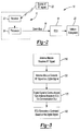
- FIG. 3 is a flowchart illustrating operation of the communication system of FIG. 1 ;
- FIG. 4 is a block diagram of a communication system including a plurality of receivers according to the principles of the present disclosure.
- FIG. 5 is a block diagram of another embodiment of the communication system according to the principles of the present disclosure.
- Example embodiments are provided so that this disclosure will be thorough, and will fully convey the scope to those who are skilled in the art. Numerous specific details are set forth such as examples of specific components, devices, and methods, to provide a thorough understanding of embodiments of the present disclosure. It will be apparent to those skilled in the art that specific details need not be employed, that example embodiments may be embodied in many different forms and that neither should be construed to limit the scope of the disclosure. In some example embodiments, well-known processes, well-known device structures, and well-known technologies are not described in detail.
- first, second, third, etc. may be used herein to describe various elements, components, regions, layers and/or sections, these elements, components, regions, layers and/or sections should not be limited by these terms. These terms may be only used to distinguish one element, component, region, layer or section from another region, layer or section. Terms such as “first,” “second,” and other numerical terms when used herein do not imply a sequence or order unless clearly indicated by the context. Thus, a first element, component, region, layer or section discussed below could be termed a second element, component, region, layer or section without departing from the teachings of the example embodiments.
- a communication system 10 may include an antenna module 12 , an electronic control unit (ECU) 14 , and a communication bus 16 .
- the communication system 10 may be installed in a vehicle 18 , as shown in FIG. 1 .
- the antenna module 12 may receive a radio frequency (RF) signal, digitize the signal, and communicate the digital signal to the ECU 14 via the communication bus 16 or any other communication medium.
- the ECU 14 may generate a command signal based on the digital signal received from the antenna module 12 and may communicate the command signal to a vehicle subsystem 20 .
- RF radio frequency
- the antenna module 12 may include an integrated receiver 22 and processor 24 . Integrating the receiver 22 and the processor 24 into a single unit (i.e., the antenna module 12 ) may reduce cost and complexity of manufacturing the vehicle 18 and may be more readily packaged into the vehicle 18 .
- FIG. 1 depicts the antenna module 12 being disposed in the rear portion of the vehicle 18 , the antenna module 12 could be disposed in any other location of the vehicle 18 .
- the antenna module 12 may be located within the vehicle 18 according to packaging, reception, and/or other constraints and/or requirements.
- the receiver 22 may receive analog radio frequency signals from an RF source 23 such as a remote keyless entry fob, a tire pressure monitoring system, or other RFID devices, for example, or any other device that broadcasts a radio frequency signal.
- the receiver 22 could be an antenna arm such as a monopole, meander line, simple loop, fractal tree, or other antenna structure.
- the antenna module 12 could include a plurality of receivers 22 forming a diversity antenna, which may be of the type disclosed in U.S. Patent Application Publication Nos. 2006/0170610 and 2008/0020723, the disclosures of which are hereby incorporated by reference.
- the plurality of receivers 22 could be disposed on the same or different circuit boards, may have different gains, and could be in communication with a switching circuit 26 .
- the switching circuit 26 may be any type of real electrical switch and may select an optimal signal among the plurality of receivers 22 based on the greatest signal-to-noise ratio and may then allow the optimal signal to be communicated to the ECU 14 .
- the communication system 10 could include a plurality of antenna modules 12 ( FIG. 5 ).
- Each of the plurality of antenna modules 12 could be disposed in different locations of the vehicle 18 , such as the front, middle, and/or back of the vehicle 18 , for example.
- Each of the plurality of antenna modules 12 may include one or more receivers 22 and a processor 24 .
- Each of the plurality of receivers 22 may be in communication with the switching circuit 26 , which may be a real electrical switch or a logical switch and may selectively allow communication between one of the receivers 22 and the processor 24 or the ECU 14 .
- the switching circuit 26 could include a port or router in the communication bus 16 .
- the receiver 22 and the processor 24 may be integrated into the antenna module 12 .
- the processor 24 may be in communication with the receiver 22 and may include a linear or non-linear analog-to-digital converter (ADC) that converts the analog RF signal received by the receiver 22 into a digital signal. Digitization of the RF signal could be accomplished via sampling, binary filtering, or data processing, for example, or by any other analog-to-digital conversion method.
- ADC analog-to-digital converter
- the processor 24 may be in communication with the ECU 14 via the communication bus 16 .
- the communication bus 16 may include standard non-coaxial vehicle wiring such as a local interconnect network (LIN), a controller area network (CAN), or J1850 network, for example, or any other local network or communication medium.
- the standard wiring of the communication bus 16 allows the antenna module 12 and the ECU 14 to be located in separate areas of the vehicle 18 . Since the antenna module 12 and ECU 14 are coupled via standard vehicle wiring, and not via a dedicated coax cable, the antenna module 12 may be positioned at an optimum location in the vehicle 18 for the antenna module 12 irrespective of the position of the ECU 14 . Furthermore, by eliminating use of a dedicated coax cable that would otherwise be employed to transmit an RF signal from the receiver 22 to the ECU 14 , and relying instead on existing vehicle wiring, the overall cost and complexity of the vehicle 18 is reduced.
- the ECU 14 may be disposed in an instrument panel 28 of the vehicle 18 , proximate other vehicle electronics.
- the antenna module 12 may be remotely located relative to the ECU 14 , for example, in the front or rear portion of the vehicle 18 or otherwise spaced apart from sources of electromagnetic interference that may hinder reception of the RF signal.
- Analog signals may be susceptible to electromagnetic interference, while digital signals are not.
- the antenna module 12 may be spaced apart from the ECU 14 to receive the analog RF signal, convert the analog signal to a digital signal in the antenna module 12 , and transmit the digital signal to the ECU 14 via the standard wiring of the communication bus 16 .
- the communication system 10 disclosed herein does not need to employ coax cable to transmit information from the antenna module 12 to the ECU 14 , thereby reducing manufacturing cost and complexity.
- the ECU 14 may be a control module disposed in, on, or proximate to the instrument panel 28 ( FIG. 1 ) of the vehicle 18 , for example, or any other portion of the vehicle 18 .
- the term “electronic control module” or “ECU” may refer to, be part of, or include an Application Specific Integrated Circuit (ASIC), an electronic circuit, a processor (shared, dedicated or group) and/or memory (shared, dedicated or group) that execute one or more software or firmware programs, a combinational logic circuit and/or other suitable components that provide the described functionality.
- the ECU 14 may receive the digital signal from the processor 24 via the communication bus 16 , and may generate an executable command based on information provided by the digital signal.
- the executable command may be communicated to the vehicle subsystem 20 , which may include a power door lock system, a tire pressure monitoring system, a remote engine starter system, an alarm system, a remote diagnostic system, or any other electrically actuated system of the vehicle 18 .
- the vehicle subsystem 20 may include a power door lock system, a tire pressure monitoring system, a remote engine starter system, an alarm system, a remote diagnostic system, or any other electrically actuated system of the vehicle 18 .
- the RF source 23 which, as described above, could be a key fob for a remote keyless entry system, may broadcast an analog RF signal in the proximity of the vehicle 18 .
- the antenna module 12 may receive the RF signal in the receiver 22 at step 110 .
- the receiver 22 may communicate the RF signal to the processor 24 , where the analog signal may be converted to a digital signal at step 120 , as described above.
- the digital signal may then be transmitted from the antenna module to the ECU 14 via the communication bus 16 at step 130 .
- the ECU 14 may generate a command signal at step 140 and communicate the command signal to the vehicle subsystem 20 which, as described above, could be a power door lock system.
- the command signal may allow the power door lock system to lock or unlock one or more doors of the vehicle 18 , for example.
- the communication system 10 could include an additional receiver that receives an RF signal and communicates an analog signal to the ECU 14 via a coaxial cable. Such an embodiment may provide additional wide bands and channels and improve gain and performance.
- the additional receiver could be integrated into the ECU 14 or the additional receiver could be external to the ECU 14 and located in or proximate to the instrument panel 28 , for example.
- a manufacturer may choose to provide the ECU 14 with an integrated receiver on all vehicles and only add an external receiver and/or the antenna module 12 on vehicles having a long range communication feature, such as remote start feature, for example.
Abstract
Description
Claims (20)
Priority Applications (1)
| Application Number | Priority Date | Filing Date | Title |
|---|---|---|---|
| US12/705,669 US8254869B2 (en) | 2009-02-19 | 2010-02-15 | Smart antenna module |
Applications Claiming Priority (2)
| Application Number | Priority Date | Filing Date | Title |
|---|---|---|---|
| US15368709P | 2009-02-19 | 2009-02-19 | |
| US12/705,669 US8254869B2 (en) | 2009-02-19 | 2010-02-15 | Smart antenna module |
Publications (2)
| Publication Number | Publication Date |
|---|---|
| US20100210234A1 US20100210234A1 (en) | 2010-08-19 |
| US8254869B2 true US8254869B2 (en) | 2012-08-28 |
Family
ID=42560369
Family Applications (1)
| Application Number | Title | Priority Date | Filing Date |
|---|---|---|---|
| US12/705,669 Active 2030-11-28 US8254869B2 (en) | 2009-02-19 | 2010-02-15 | Smart antenna module |
Country Status (1)
| Country | Link |
|---|---|
| US (1) | US8254869B2 (en) |
Cited By (4)
| Publication number | Priority date | Publication date | Assignee | Title |
|---|---|---|---|---|
| US20130297194A1 (en) * | 2012-05-04 | 2013-11-07 | Lightwave Technologies | System and method for remote starting a vehicle equipped with a smart start system |
| US9536365B2 (en) | 2013-05-29 | 2017-01-03 | Lightwave Technology Inc. | System and method for keyless entry and remote starting vehicle with an OEM remote embedded in vehicle |
| US10211914B2 (en) | 2011-11-15 | 2019-02-19 | Aviation Communication & Surveillance Systems, Llc | Systems and methods for providing remote L-band smart antennas |
| US11018754B2 (en) * | 2018-08-07 | 2021-05-25 | Appareo Systems, Llc | RF communications system and method |
Families Citing this family (3)
| Publication number | Priority date | Publication date | Assignee | Title |
|---|---|---|---|---|
| JP4735708B2 (en) * | 2008-11-19 | 2011-07-27 | 株式会社デンソー | Vehicle receiver system |
| US8566632B2 (en) * | 2011-01-18 | 2013-10-22 | Nxp B.V. | Multi-rate sampling for network receiving nodes using distributed clock synchronization |
| US9606523B2 (en) * | 2012-04-04 | 2017-03-28 | Philips Lighting Holding B.V. | Apparatus and methods for external programming of processor of LED driver |
Citations (12)
| Publication number | Priority date | Publication date | Assignee | Title |
|---|---|---|---|---|
| US4039953A (en) * | 1974-11-07 | 1977-08-02 | Decca Limited | Automatic aerial attenuator |
| US6417766B1 (en) | 2000-01-14 | 2002-07-09 | Schrader-Bridgeport International, Inc. | Method and apparatus for identifying remote sending units in a tire pressure monitor system of a vehicle using secondary modulation of wheel rotation |
| US6518876B1 (en) | 2000-04-25 | 2003-02-11 | Schrader-Bridgeport International, Inc. | Determination of wheel sensor position using radio frequency detectors in an automotive remote tire monitor system |
| US6710708B2 (en) | 1999-02-05 | 2004-03-23 | Schrader-Bridgeport International, Inc. | Method and apparatus for a remote tire pressure monitoring system |
| US6882270B2 (en) | 2001-10-29 | 2005-04-19 | Schrader Bridgeport International, Inc. | Determination of wheel sensor position using radio frequency detectors in an automotive remote tire monitor system |
| US20050123071A1 (en) * | 2002-07-30 | 2005-06-09 | Hiroki Okada | Digital signal processing and receiving apparatus and method |
| US7079903B2 (en) | 2003-03-03 | 2006-07-18 | Greatbatch-Hittman, Inc. | Low polarization coatings for implantable electrodes |
| US20060170610A1 (en) | 2005-01-28 | 2006-08-03 | Tenatronics Limited | Antenna system for remote control automotive application |
| US20080020723A1 (en) | 2005-01-28 | 2008-01-24 | Victor Rabinovich | Antenna system for remote control automotive application |
| US7362218B2 (en) | 2004-01-20 | 2008-04-22 | Schrader Bridgeport International, Inc. | Motion detection using a shock sensor in a remote tire pressure monitoring system |
| US7367227B2 (en) | 2004-01-20 | 2008-05-06 | Schrader Bridgeport International | Determination of wheel sensor position using shock sensors and a wireless solution |
| US7423532B2 (en) | 2001-10-29 | 2008-09-09 | Schrader Bridgeport International, Inc. | Determination of wheel sensor position using a single radio frequency detector in an automotive remote tire monitor system |
-
2010
- 2010-02-15 US US12/705,669 patent/US8254869B2/en active Active
Patent Citations (16)
| Publication number | Priority date | Publication date | Assignee | Title |
|---|---|---|---|---|
| US4039953A (en) * | 1974-11-07 | 1977-08-02 | Decca Limited | Automatic aerial attenuator |
| US6906624B2 (en) | 1999-02-05 | 2005-06-14 | Schrader-Bridgeport International, Inc. | Method and apparatus for a remote tire pressure monitoring system |
| US7088226B2 (en) | 1999-02-05 | 2006-08-08 | Schrader-Bridgeport International, Inc. | Method and apparatus for a remote tire pressure monitoring system |
| US6710708B2 (en) | 1999-02-05 | 2004-03-23 | Schrader-Bridgeport International, Inc. | Method and apparatus for a remote tire pressure monitoring system |
| US6580365B2 (en) | 2000-01-14 | 2003-06-17 | Schrader-Bridgeport International, Inc. | Method and apparatus for identifying remote sending units in a tire pressure monitor system of a vehicle using secondary modulation of wheel rotation |
| US6417766B1 (en) | 2000-01-14 | 2002-07-09 | Schrader-Bridgeport International, Inc. | Method and apparatus for identifying remote sending units in a tire pressure monitor system of a vehicle using secondary modulation of wheel rotation |
| US6809639B2 (en) | 2000-04-25 | 2004-10-26 | Schrader-Bridgeport International, Inc. | Determination of wheel sensor position using radio frequency detectors in an automotive remote tire monitor system |
| US6518876B1 (en) | 2000-04-25 | 2003-02-11 | Schrader-Bridgeport International, Inc. | Determination of wheel sensor position using radio frequency detectors in an automotive remote tire monitor system |
| US6882270B2 (en) | 2001-10-29 | 2005-04-19 | Schrader Bridgeport International, Inc. | Determination of wheel sensor position using radio frequency detectors in an automotive remote tire monitor system |
| US7423532B2 (en) | 2001-10-29 | 2008-09-09 | Schrader Bridgeport International, Inc. | Determination of wheel sensor position using a single radio frequency detector in an automotive remote tire monitor system |
| US20050123071A1 (en) * | 2002-07-30 | 2005-06-09 | Hiroki Okada | Digital signal processing and receiving apparatus and method |
| US7079903B2 (en) | 2003-03-03 | 2006-07-18 | Greatbatch-Hittman, Inc. | Low polarization coatings for implantable electrodes |
| US7362218B2 (en) | 2004-01-20 | 2008-04-22 | Schrader Bridgeport International, Inc. | Motion detection using a shock sensor in a remote tire pressure monitoring system |
| US7367227B2 (en) | 2004-01-20 | 2008-05-06 | Schrader Bridgeport International | Determination of wheel sensor position using shock sensors and a wireless solution |
| US20060170610A1 (en) | 2005-01-28 | 2006-08-03 | Tenatronics Limited | Antenna system for remote control automotive application |
| US20080020723A1 (en) | 2005-01-28 | 2008-01-24 | Victor Rabinovich | Antenna system for remote control automotive application |
Cited By (6)
| Publication number | Priority date | Publication date | Assignee | Title |
|---|---|---|---|---|
| US10211914B2 (en) | 2011-11-15 | 2019-02-19 | Aviation Communication & Surveillance Systems, Llc | Systems and methods for providing remote L-band smart antennas |
| US20130297194A1 (en) * | 2012-05-04 | 2013-11-07 | Lightwave Technologies | System and method for remote starting a vehicle equipped with a smart start system |
| US10400735B2 (en) * | 2012-05-04 | 2019-09-03 | Light Wave Technology Inc. | System and method for remote starting a vehicle equipped with a smart start system |
| US9536365B2 (en) | 2013-05-29 | 2017-01-03 | Lightwave Technology Inc. | System and method for keyless entry and remote starting vehicle with an OEM remote embedded in vehicle |
| US10196039B2 (en) | 2013-05-29 | 2019-02-05 | Light Wave Technology Inc. | System and method for keyless entry and remote starting vehicle with an OEM remote embedded in vehicle |
| US11018754B2 (en) * | 2018-08-07 | 2021-05-25 | Appareo Systems, Llc | RF communications system and method |
Also Published As
| Publication number | Publication date |
|---|---|
| US20100210234A1 (en) | 2010-08-19 |
Similar Documents
| Publication | Publication Date | Title |
|---|---|---|
| US8254869B2 (en) | Smart antenna module | |
| US8319693B2 (en) | Antenna module for a motor vehicle | |
| JP5662906B2 (en) | Position detection system and position determination method | |
| CN101136114B (en) | Keyless passive entry system | |
| US8630749B2 (en) | Vehicle control system, electronic control device, and communication method | |
| JP2012523795A (en) | LIN bus remote control system | |
| US20080150712A1 (en) | Tire pressure monitoring (tpm) and remote keyless entry (rke) system | |
| US8284040B2 (en) | Receiver system for vehicles | |
| US20080100429A1 (en) | Tire pressure monitoring (tpm) and remote keyless entry (rke) system for a vehicle | |
| US10777875B2 (en) | Detection device and detection system | |
| JP2011146909A (en) | Antenna structure of electronic key system | |
| US9384610B2 (en) | On-board apparatus control system | |
| US8410631B2 (en) | Method for transmitting and/or receiving signals for at least a first and a second different service, particularly in a vehicle | |
| US20070016342A1 (en) | Interface to vehicle security and convenience systems | |
| JP2010137780A (en) | Power transmission type wireless communication system | |
| JP2006246135A (en) | Receiver for smart entry system | |
| US6937197B2 (en) | Antenna for a central locking system of an automotive vehicle | |
| JP6522902B2 (en) | Position estimation device | |
| JP5088026B2 (en) | Smart keyless entry system | |
| JP2008078971A (en) | In-vehicle wireless receiver and wireless-receiver setting method | |
| US11733376B2 (en) | Vehicle radar system with solution for ADC saturation | |
| JP2010031589A (en) | Smart key system | |
| JP2008174960A (en) | Keyless system for vehicle | |
| CN114979937A (en) | Bluetooth positioning device and method, vehicle positioning system and method and vehicle | |
| JP2008169663A (en) | Portable machine and vehicular remote control system using the same |
Legal Events
| Date | Code | Title | Description |
|---|---|---|---|
| AS | Assignment |
Owner name: CHRYSLER GROUP LLC, MICHIGAN Free format text: ASSIGNMENT OF ASSIGNORS INTEREST;ASSIGNORS:HYDE, STEPHEN L.;ALKHATEEB, BASIM;SIGNING DATES FROM 20090209 TO 20090210;REEL/FRAME:026256/0883 |
|
| AS | Assignment |
Owner name: CITIBANK, N.A., NEW YORK Free format text: SECURITY AGREEMENT;ASSIGNOR:CHRYSLER GROUP LLC;REEL/FRAME:026396/0780 Effective date: 20110524 |
|
| AS | Assignment |
Owner name: CITIBANK, N.A., NEW YORK Free format text: SECURITY AGREEMENT;ASSIGNOR:CHRYSLER GROUP LLC;REEL/FRAME:026426/0644 Effective date: 20110524 |
|
| STCF | Information on status: patent grant |
Free format text: PATENTED CASE |
|
| AS | Assignment |
Owner name: JPMORGAN CHASE BANK, N.A., ILLINOIS Free format text: SECURITY AGREEMENT;ASSIGNOR:CHRYSLER GROUP LLC;REEL/FRAME:032384/0640 Effective date: 20140207 |
|
| AS | Assignment |
Owner name: FCA US LLC, MICHIGAN Free format text: CHANGE OF NAME;ASSIGNOR:CHRYSLER GROUP LLC;REEL/FRAME:035553/0356 Effective date: 20141203 |
|
| AS | Assignment |
Owner name: FCA US LLC, FORMERLY KNOWN AS CHRYSLER GROUP LLC, Free format text: RELEASE OF SECURITY INTEREST RELEASING SECOND-LIEN SECURITY INTEREST PREVIOUSLY RECORDED AT REEL 026426 AND FRAME 0644, REEL 026435 AND FRAME 0652, AND REEL 032384 AND FRAME 0591;ASSIGNOR:CITIBANK, N.A.;REEL/FRAME:037784/0001 Effective date: 20151221 |
|
| FPAY | Fee payment |
Year of fee payment: 4 |
|
| AS | Assignment |
Owner name: FCA US LLC (FORMERLY KNOWN AS CHRYSLER GROUP LLC), Free format text: RELEASE BY SECURED PARTY;ASSIGNOR:CITIBANK, N.A.;REEL/FRAME:042885/0255 Effective date: 20170224 |
|
| AS | Assignment |
Owner name: FCA US LLC (FORMERLY KNOWN AS CHRYSLER GROUP LLC), Free format text: RELEASE BY SECURED PARTY;ASSIGNOR:JPMORGAN CHASE BANK, N.A.;REEL/FRAME:048177/0356 Effective date: 20181113 |
|
| MAFP | Maintenance fee payment |
Free format text: PAYMENT OF MAINTENANCE FEE, 8TH YEAR, LARGE ENTITY (ORIGINAL EVENT CODE: M1552); ENTITY STATUS OF PATENT OWNER: LARGE ENTITY Year of fee payment: 8 |
|
| MAFP | Maintenance fee payment |
Free format text: PAYMENT OF MAINTENANCE FEE, 12TH YEAR, LARGE ENTITY (ORIGINAL EVENT CODE: M1553); ENTITY STATUS OF PATENT OWNER: LARGE ENTITY Year of fee payment: 12 |