US8253538B1 - Asset management using mobile radio-frequency identification (RFID) readers - Google Patents
Asset management using mobile radio-frequency identification (RFID) readers Download PDFInfo
- Publication number
- US8253538B1 US8253538B1 US12/436,460 US43646009A US8253538B1 US 8253538 B1 US8253538 B1 US 8253538B1 US 43646009 A US43646009 A US 43646009A US 8253538 B1 US8253538 B1 US 8253538B1
- Authority
- US
- United States
- Prior art keywords
- radio
- location
- assets
- frequency identification
- asset
- Prior art date
- Legal status (The legal status is an assumption and is not a legal conclusion. Google has not performed a legal analysis and makes no representation as to the accuracy of the status listed.)
- Expired - Fee Related, expires
Links
Images


Classifications
-
- G—PHYSICS
- G06—COMPUTING; CALCULATING OR COUNTING
- G06K—GRAPHICAL DATA READING; PRESENTATION OF DATA; RECORD CARRIERS; HANDLING RECORD CARRIERS
- G06K7/00—Methods or arrangements for sensing record carriers, e.g. for reading patterns
- G06K7/10—Methods or arrangements for sensing record carriers, e.g. for reading patterns by electromagnetic radiation, e.g. optical sensing; by corpuscular radiation
- G06K7/10009—Methods or arrangements for sensing record carriers, e.g. for reading patterns by electromagnetic radiation, e.g. optical sensing; by corpuscular radiation sensing by radiation using wavelengths larger than 0.1 mm, e.g. radio-waves or microwaves
- G06K7/10366—Methods or arrangements for sensing record carriers, e.g. for reading patterns by electromagnetic radiation, e.g. optical sensing; by corpuscular radiation sensing by radiation using wavelengths larger than 0.1 mm, e.g. radio-waves or microwaves the interrogation device being adapted for miscellaneous applications
- G06K7/10475—Methods or arrangements for sensing record carriers, e.g. for reading patterns by electromagnetic radiation, e.g. optical sensing; by corpuscular radiation sensing by radiation using wavelengths larger than 0.1 mm, e.g. radio-waves or microwaves the interrogation device being adapted for miscellaneous applications arrangements to facilitate interaction with further interrogation devices, e.g. such that at least two interrogation devices may function and cooperate in a network of such devices
-
- H—ELECTRICITY
- H04—ELECTRIC COMMUNICATION TECHNIQUE
- H04Q—SELECTING
- H04Q2213/00—Indexing scheme relating to selecting arrangements in general and for multiplex systems
- H04Q2213/13095—PIN / Access code, authentication
Definitions
- the present disclosure relates generally to radio-frequency identification (RFID). More particularly, the present disclosure relates to asset management using a mobile RFID reader.
- RFID radio-frequency identification
- RFID radio-frequency identification
- RF radio-frequency
- Current RFID systems for asset management are generally implemented using one or more fixed RFID readers permanently deployed in each room where the assets are located. Such systems can generally determine in which room an asset is located. In rooms having multiple RFID readers, current systems can determine an approximate location (zone) of an asset in a room based on the location of the RFID reader receiving the strongest RF signal from the asset.
- an embodiment features an apparatus comprising: a mobile RFID reader adapted to receive radio-frequency (RF) signals from a plurality of RFID tags, wherein each RF signal represents a tag identifier associated with the respective RFID tag, and wherein the RFID tags include a plurality of asset tags and a plurality of location tags, wherein each of the asset tags is associated with a respective one of a plurality of assets, and wherein each of the location tags is associated with a respective one of a plurality of first locations; and an association module adapted to generate first associations between each of the assets and one or more of the first locations based on the tag identifiers.
- RF radio-frequency
- an embodiment features a method comprising: receiving radio-frequency (RF) signals from a plurality of radio-frequency identification (RFID) tags into a mobile RFID reader, wherein each RF signal represents a tag identifier associated with the respective RFID tag, and wherein the RFID tags include a plurality of asset tags and a plurality of location tags, wherein each of the asset tags is associated with a respective one of a plurality of assets, and wherein each of the location tags is associated with a respective one of a plurality of first locations; and generating first associations between each of the assets and one or more of the first locations based on the tag identifiers.
- RF radio-frequency
- RFID radio-frequency identification
- an embodiment features an apparatus comprising: a network interface adapted to receive a plurality of first tag identifiers, wherein each of the first tag identifiers is associated with a respective RFID tag, and wherein the RFID tags include a plurality of asset tags and a plurality of location tags; a RFID database adapted to store a plurality of entries, wherein the entries comprise a plurality of first entries, wherein each of the first entries associates one of the asset tags with a respective one of a plurality of assets, and a plurality of second entries, wherein each of the second entries associates one of the location tags with a respective one of a plurality of locations; and an association module adapted to generate first associations between each of the assets and one or more of the first locations based on the first tag identifiers, the first entries, and the second entries.
- an embodiment features a computer program comprising: instructions for receiving a plurality of tag identifiers, wherein each tag identifier is represented by a respective radio-frequency (RF) signal received from a radio-frequency identification (RFID) tag into a mobile RFID reader, wherein the RFID tags include a plurality of asset tags and a plurality of location tags, wherein each of the asset tags is associated with a respective one of a plurality of assets, and wherein each of the location tags is associated with a respective one of a plurality of first locations; and instructions for generating first associations between each of the assets and one or more of the first locations based on the tag identifiers.
- RF radio-frequency
- FIG. 1 shows elements of a radio-frequency identification (RFID) system in scan mode according to some embodiments.
- RFID radio-frequency identification
- FIG. 2 shows a process for the RFID system of FIG. 1 in scan mode according to some embodiments.
- FIG. 3 shows elements of a RFID system in search mode according to some embodiments.
- FIG. 4 shows a process for the RFID system of FIG. 3 in search mode according to some embodiments.
- FIG. 5 shows elements of a RFID system in locate mode according to some embodiments.
- FIG. 6 shows a process for the RFID system of FIG. 5 in locate mode according to some embodiments.
- FIG. 7 shows elements of a RFID system in doorway mode according to some embodiments.
- FIG. 8 shows a process for the RFID system of FIG. 7 in doorway mode according to some embodiments.
- FIG. 9 shows elements of a RFID system including a standalone mobile RFID scanner according to some embodiments.
- Embodiments of the present disclosure provide elements of a low-cost, scalable system for asset management using mobile radio-frequency identification (RFID) readers.
- the system can operate in several modes, including scan, search, locate, and doorway modes.
- the system can also include a data entry mode for entry of the operating parameters described below into an operating database.
- the parameters can include tag ID, asset, location, make, model, serial number, and the like.
- a mobile RFID reader receives radio-frequency (RF) signals from RFID tags as the mobile RFID reader is moved relative to the RFID tags.
- Each RF signal represents a tag identifier associated with the respective RFID tag.
- the RFID tags include asset tags and location tags. Each asset tag is associated with an asset. Each location tag is associated with a location.
- the assets can be electronic devices such as computers, each having a respective RFID tag attached, and the locations can be shelving units in which the assets are stored.
- An association module generates associations between each of the assets and one or more of the locations based on the RF signals. The association module can generate the associations based on times of reception of the RF signals, the order of reception of the RF signals, and the like.
- an input module accepts an indication of one or more of the assets. Then a search module identifies one or more of the locations based on the indication and the associations generated during scan mode.
- an input module accepts an indication of one or more of the assets. Then a locate module generates an alert when an RF signal representing a tag identifier associated with the indicated asset(s) is received by the mobile RFID reader.
- a motion detector and a fixed RFID reader are fixed in a location such as a doorway of a room in which the assets are stored.
- a camera creates an image of the location
- the fixed RFID reader captures any RF signals present in the location.
- the association module then generates an association among the location, the image, and any assets associated with tag identifiers represented by the RF signals captured by the fixed RFID reader.
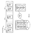
- FIG. 1 shows elements of a radio-frequency identification (RFID) system 100 in scan mode according to some embodiments.
- RFID radio-frequency identification
- the elements of RFID system 100 are presented in one arrangement, other embodiments may feature other arrangements, as will be apparent to one skilled in the relevant arts based on the disclosure and teachings provided herein.
- the elements of RFID system 100 can be implemented in hardware, software, or combinations thereof.
- RFID system 100 includes five assets 102 A-E stored in three storage units 104 A-C.
- Assets 102 can include any sort of asset.
- assets 102 can include electronic devices and the like.
- Storage units 104 can include any sort of storage units as long as the RFID asset tags of the assets 102 stored therein are sufficiently exposed for reading by an RFID reader.
- storage units 104 can include shelving units, disk drive bays and the like.
- individual disk drives mounted in computer disk drive bays can be tagged individually as assets 102 , for example using tag hangers to expose the tags for reading.
- RFID tags are attached to each asset 102 and storage unit 104 . Each RFID tag has a different tag identifier. For clarity of description, the RFID tags attached to assets 102 are referred to as “asset tags” AT 1 -AT 5 , while the RFID tags attached to storage units 104 are referred to as “location tags” LT 1 -LT 3 . However, asset tags AT and location tags LT can be identical except for the tag identifiers encoded therein. RFID tags AT, LT can be implemented in any manner, can be active or passive, and the like.
- RFID system 100 further includes a mobile RFID scanner 106 in communication with a server computer 108 over a network 110 .
- Network 110 can be implemented as a wide-area network (WAN) such as the Internet, a local-area network (LAN), or the like. In other embodiments, network 110 can be replaced by a direct communication link.
- WAN wide-area network
- LAN local-area network
- Mobile RFID scanner 106 includes one or more RFID antennas 112 , a mobile RFID reader 114 , a client computer 116 , and a network interface 118 .
- RFID antenna(s) 112 and RFID reader 114 can be implemented in any manner.
- RFID antennas 112 and mobile RFID reader 114 can be commercially-available units.
- Client computer 116 can be implemented as a commercially-available general-purpose computer, as a special-purpose computer, and the like.
- Network interface 118 can be implemented in any manner.
- network interface 118 can be a commercially-available unit.
- network interface 118 is preferably a wireless network interface.
- Mobile RFID scanner 106 is shown mounted on wheels 120 for mobility.
- mobile RFID scanner 106 can be mounted on a standard utility cart, as a handheld unit, and the like.
- Mobile RFID scanner 106 can be mounted on a truck, forklift, and the like.
- multiple mobile RFID scanners 106 can be implemented on a single platform or vehicle.
- Server computer 108 includes a network interface 122 , an association module 124 , and an RFID database 126 .
- Server computer 108 can be implemented as a commercially-available general-purpose computer, as a special-purpose computer, and the like.
- Network interface 122 can be implemented in any manner.
- network interface 122 can be a commercially-available unit.
- Association module 124 can be implemented in any manner.
- association module 124 can be implemented as a software module for execution by a processor of server computer 108 .
- RFID database 126 can be stored on a memory, storage device, or the like of server computer 108 .
- each RFID tag AT, LT is registered in RFID database 126 . That is, an entry is created in RFID database 126 for each RFID tag AT, LT.
- RFID database 126 can include an asset table for asset tags AT and a location table for location tags LT.
- Example asset and location tables for the example of FIG. 1 are presented below as Tables 1 and 2, respectively.
- each entry for asset tags AT includes the tag identifier encoded into the asset tag AT, along with information describing the tagged asset 102 such as make, model, serial number, and the like.
- tag identifiers For clarity of description, reference numbers from FIG. 1 are used as the tag identifiers in Table 1.
- each entry for location tags LT includes the tag identifier encoded into the location tag LT, along with information describing the location of the tagged storage unit 104 such as building number, room number, aisle, storage unit number, and the like.
- the location information can include, city, state, country, and the like.
- reference numbers from FIG. 1 are used as the tag identifiers in Table 2.
- storage units 104 are the first three storage units on aisle A in room 222 of a one-building implementation.
- FIG. 2 shows a process 200 for RFID system 100 of FIG. 1 in scan mode according to some embodiments.
- the elements of process 200 are presented in one arrangement, other embodiments may feature other arrangements, as will be apparent to one skilled in the relevant arts based on the disclosure and teachings provided herein.
- some or all of the steps of process 200 can be executed in a different order, concurrently, and the like.
- mobile RFID scanner 106 is set in motion (step 202 ).
- the motion of mobile RFID scanner 106 can be controlled manually or automatically.
- mobile RFID scanner 106 can be pushed or driven by a human operator past storage units 104 .
- mobile RFID scanner 106 can automatically follow a magnetic or optical track affixed to the floor past storage units 104 .
- mobile RFID reader 114 receives radio-frequency (RF) signals from RFID tags AT, LT through RFID antenna 112 (step 204 ). Each RF signal represents a tag identifier associated with the respective RFID tag AT, LT.
- Client computer 116 collects the tag identifiers (step 206 ), and passes the tag identifiers to server computer 108 , either individually or in batches.
- association module 124 generates associations between assets 102 and the locations of storage units 104 based on the tag identifiers received from mobile RFID scanner 106 (step 208 ).
- the associations can be generated based on times of reception of the RF signals by mobile RFID reader 114 , the order of reception of the RF signals, and the like.
- the tag identifiers are collected in the following order, with mobile RFID scanner 106 moving from left to right in FIG. 1 : LT 1 , AT 1 , AT 2 , LT 2 , AT 3 , LT 3 , AT 4 , AT 5 .
- association module 124 creates the associations shown in Table 3, referred to as the cross-reference table, which is added to RFID database 126 .
- Tables 1-3 together now define associations between assets 102 and their locations in storage units 104 . These associations can be used in search mode, locate mode, and doorway mode, as described below. Referring to Table 3, note that each asset 102 can have multiple locations if desired.
- FIG. 3 shows elements of a radio-frequency identification (RFID) system 300 in search mode according to some embodiments.
- RFID radio-frequency identification
- the elements of RFID system 300 are presented in one arrangement, other embodiments may feature other arrangements, as will be apparent to one skilled in the relevant arts based on the disclosure and teachings provided herein.
- the elements of RFID system 300 can be implemented in hardware, software, or combinations thereof.
- RFID system 300 includes a client computer 302 in communication with server computer 108 over network 110 .
- Server computer 108 and network 110 can be implemented as described above.
- Client computer 302 can be implemented as a commercially-available general-purpose computer, as a special-purpose computer, and the like.
- Client computer 302 includes a network interface 304 , an input module 306 , and a search module 308 .
- Input module 306 and search module 308 can be implemented in any manner.
- input module 306 and search module 308 can be implemented as software modules for execution by a processor of client computer 302 .
- all or part of input module 306 and search module 308 can be implemented on server computer 108 .
- Network interface 304 can be implemented in any manner.
- network interface 304 can be a commercially-available unit.
- FIG. 4 shows a process 400 for RFID system 300 of FIG. 3 in search mode according to some embodiments.
- the elements of process 400 are presented in one arrangement, other embodiments may feature other arrangements, as will be apparent to one skilled in the relevant arts based on the disclosure and teachings provided herein.
- some or all of the steps of process 400 can be executed in a different order, concurrently, and the like.
- input module 306 accepts an indication of one or more assets 102 (step 402 ).
- input module 306 can provide a graphical user interface (GUI) where a user can enter one or more search parameters such as values for the fields shown in Table 1. That is, a user can specify the make, model, serial number, and the like, of the asset 102 sought.
- GUI graphical user interface
- input module 306 can provide a GUI listing some or all of the assets 102 in RFID database 126 , allowing the user to select one or more of the assets 102 .
- Mobile RFID scanner 106 sends the indication of the asset(s) to server computer 108 .
- network interface 118 of mobile RFID scanner 106 transmits the indication
- network interface 122 of server computer 108 receives the indication.
- Search module 308 identifies one or more locations based on the user-provided indication of asset(s) 102 and the associations in RFID database 126 (step 404 ). For example, if the user indicates asset 102 C, search module 308 indexes the cross-reference table (Table 3 above) using the asset tag identifier AT 3 , which returns the location tag identifier LT 3 . Search module 308 then indexes the location table (Table 2 above), which returns the location as Room 222 , Aisle A, Unit 2 . Server computer provides the location to mobile RFID scanner 106 using network interfaces 122 and 118 .
- location tags can be placed more densely than one per storage unit 104 .
- search module 308 can return the locations that surround the asset 102 . For example, assume that storage units 104 A-C are not separate storage units, but form a single storage unit 104 . In such embodiments, search module 308 can return the location of asset 102 C as being between location tags LT 2 and LT 3 in Room 222 , Aisle A.
- FIG. 5 shows elements of a radio-frequency identification (RFID) system 500 in locate mode according to some embodiments.
- RFID radio-frequency identification
- the elements of RFID system 500 are presented in one arrangement, other embodiments may feature other arrangements, as will be apparent to one skilled in the relevant arts based on the disclosure and teachings provided herein.
- the elements of RFID system 500 can be implemented in hardware, software, or combinations thereof.
- RFID system 500 includes five assets 102 A-E stored in three storage units 104 A-C.
- RFID system 500 further includes mobile RFID scanner 106 in communication with server computer 108 over a network 110 .
- Mobile RFID scanner 106 includes one or more RFID antennas 112 , a mobile RFID reader 114 , a client computer 116 , and a network interface 118 .
- Server computer 108 includes a network interface 122 , an association module 124 , and an RFID database 126 . Each of these elements can be implemented as described above.
- Client computer 116 includes an input module 502 and a locate module 504 .
- Input module 502 and locate module 504 can be implemented in any manner.
- input module 502 and locate module 504 can be implemented as software modules for execution by a processor of client computer 116 .
- all or part of input module 502 and locate module 504 can be implemented on server computer 108 .
- Input module 502 and locate module 504 can also be implemented in hardware or a combination of hardware and software.
- FIG. 6 shows a process 600 for RFID system 500 of FIG. 5 in locate mode according to some embodiments.
- the elements of process 600 are presented in one arrangement, other embodiments may feature other arrangements, as will be apparent to one skilled in the relevant arts based on the disclosure and teachings provided herein.
- some or all of the steps of process 600 can be executed in a different order, concurrently, and the like.
- input module 502 accepts an indication of one or more assets 102 (step 602 ).
- input module 502 can provide a graphical user interface (GUI) where a user can enter one or more search parameters such as values for the fields shown in Table 1. That is, a user can specify the make, model, serial number, and the like, of the asset 102 to be located.
- GUI graphical user interface
- input module 502 can provide a GUI listing some or all of the assets 102 in RFID database 126 , allowing the user to select one or more of the assets 102 .
- Mobile RFID scanner 106 sends the indication of the asset(s) to server computer 108 .
- network interface 118 of mobile RFID scanner 106 transmits the indication
- network interface 122 of server computer 108 receives the indication.
- Association module 124 of server computer 108 identifies one or more tag identifiers associated with the one or more assets 102 based on the indication.
- Server computer 108 provides the tag identifiers to mobile RFID scanner 106 using network interfaces 122 and 118 .
- Mobile RFID scanner 106 is then set in motion (step 604 ), for example as described above.
- mobile RFID reader 114 receives radio-frequency (RF) signals RFID tags AT, LT through RFID antenna 112 (step 606 ), also as described above.
- RF radio-frequency
- locate module 504 When an RF signal representing a tag identifier associated with the asset(s) 102 to be located is received by mobile RFID reader 114 (step 608 ), locate module 504 generates an alert (step 610 ).
- the alert can take any form, such as a sound, light, or the like.
- FIG. 7 shows elements of a radio-frequency identification (RFID) system 700 in doorway mode according to some embodiments.
- RFID radio-frequency identification
- the elements of RFID system 700 are presented in one arrangement, other embodiments may feature other arrangements, as will be apparent to one skilled in the relevant arts based on the disclosure and teachings provided herein.
- the elements of RFID system 700 can be implemented in hardware, software, or combinations thereof.
- RFID system 700 is described as monitoring a doorway, RFID system 700 can be used to monitor any location.
- RFID system 700 may include a doorway module 702 in communications with server computer 108 over network 110 .
- Server computer 108 and network 110 can be implemented as described above.
- Doorway module 702 monitors a doorway 704 , and includes a motion detector 706 , a fixed RFID reader 710 , and a network interface 712 , and can optionally include a camera 708 .
- Doorway module 702 can also include a monitor module 714 to manage motion detector 706 , fixed RFID reader 710 , and camera 708 .
- These elements can be implemented in any manner.
- motion detector 706 , RFID reader 710 , and network interface 712 can be implemented as commercially-available units
- camera 708 can be implemented as a commercially-available IP camera or the like.
- FIG. 8 shows a process 800 for RFID system 700 of FIG. 7 in doorway mode according to some embodiments.
- the elements of process 800 are presented in one arrangement, other embodiments may feature other arrangements, as will be apparent to one skilled in the relevant arts based on the disclosure and teachings provided herein.
- some or all of the steps of process 800 can be executed in a different order, concurrently, and the like.
- step 802 when motion detector 706 detects motion in doorway 704 (step 802 ), optional camera 708 creates one or more images of doorway 704 (step 804 ), and fixed RFID reader 710 captures any RF signals present in doorway 704 (step 806 ).
- Network interface 712 transfers the image(s), and the tag identifiers represented by the captured RF signals, to server computer 108 , using network interfaces 118 and 122 .
- association module 124 generates an association among doorway 704 , the image(s), and any assets 102 associated with the tag identifiers (step 808 ).
- the association can be recorded in RFID database 126 of server computer 108 .
- This association can also include other information, such as the time and date of each image. This association can be useful when an asset 102 cannot be found in search mode or locate mode.
- Doorway mode can also be used to update the locations of assets 102 , for example to indicate that an asset 102 has left the room.
- the images associated with the asset 102 can be used to identify the last person that had possession of the asset 102 , to identify an intruder and aid in their prosecution, and the like. Multiple images of the person can be useful to improve the ability to identify the person. For example, the gap between images in a series can be approximately 1 second. If the asset still cannot be found, security personnel can use the images to investigate.
- the mobile RFID scanner is implemented as a standalone unit.
- the association module and RFID database are incorporated into the mobile RFID scanner. Therefore, no separate server is needed.
- FIG. 9 shows elements of a radio-frequency identification (RFID) system 900 including a standalone mobile RFID scanner 906 according to some embodiments.
- RFID radio-frequency identification
- the elements of standalone RFID system 900 are presented in one arrangement, other embodiments may feature other arrangements, as will be apparent to one skilled in the relevant arts based on the disclosure and teachings provided herein.
- the elements of standalone RFID system 900 can be implemented in hardware, software, or combinations thereof.
- RFID system 900 includes five assets 102 A-E stored in three storage units 104 A-C. Assets 102 and storage units 104 are tagged as described above.
- RFID system 900 further includes a standalone mobile RFID scanner 906 .
- Mobile RFID scanner 106 includes one or more RFID antennas 112 , mobile RFID reader 114 , client computer 116 , association module 124 , and RFID database 126 .
- the elements of standalone mobile RFID scanner 906 can be implemented as described above, and can operate in any of the modes described above.
- Embodiments can be implemented in digital electronic circuitry, or in computer hardware, firmware, software, or in combinations of them.
- Embodiments can be implemented in a computer program product tangibly embodied in a machine-readable storage device for execution by a programmable processor; and method steps can be performed by a programmable processor executing a program of instructions to perform functions by operating on input data and generating output.
- Embodiments can be implemented in one or more computer programs that are executable on a programmable system including at least one programmable processor coupled to receive data and instructions from, and to transmit data and instructions to, a data storage system, at least one input device, and at least one output device.
- Each computer program can be implemented in a high-level procedural or object-oriented programming language, or in assembly or machine language if desired; and in any case, the language can be a compiled or interpreted language.
- Suitable processors include, by way of example, both general and special purpose microprocessors.
- a processor will receive instructions and data from a read-only memory and/or a random access memory.
- a computer will include one or more mass storage devices for storing data files; such devices include magnetic disks, such as internal hard disks and removable disks; magneto-optical disks; and optical disks.
- Storage devices suitable for tangibly embodying computer program instructions and data include all forms of non-volatile memory, including by way of example semiconductor memory devices, such as EPROM, EEPROM, and flash memory devices; magnetic disks such as internal hard disks and removable disks; magneto-optical disks; and CD-ROM disks. Any of the foregoing can be supplemented by, or incorporated in, ASICs (application-specific integrated circuits).
- semiconductor memory devices such as EPROM, EEPROM, and flash memory devices
- magnetic disks such as internal hard disks and removable disks
- magneto-optical disks magneto-optical disks
- CD-ROM disks CD-ROM disks
Abstract
Description
| TABLE 1 |
| Asset Table |
| Tag ID | Make | Model | Serial Number | ||
| AT1 | Make1 | Model1 | Serno1 | ||
| AT2 | Make2 | Model2 | Serno2 | ||
| AT3 | Make3 | Model3 | Serno3 | ||
| AT4 | Make4 | Model4 | Serno4 | ||
| AT5 | Make5 | Model5 | Serno5 | ||
| TABLE 2 |
| Location Table |
| Tag ID | Room | Aisle | Unit | ||
| LT1 | 222 | A | 1 | ||
| LT2 | 222 | A | 2 | ||
| LT3 | 222 | A | 3 | ||
| TABLE 3 |
| Cross-Reference Table |
| Asset Tag ID | Location Tag ID1 | Location Tag ID2 |
| AT1 | LT1 | LT2 |
| AT2 | LT1 | LT2 |
| AT3 | LT2 | LT3 |
| AT4 | LT3 | LT4 |
| AT5 | LT3 | LT4 |
Claims (21)
Priority Applications (1)
| Application Number | Priority Date | Filing Date | Title |
|---|---|---|---|
| US12/436,460 US8253538B1 (en) | 2008-05-29 | 2009-05-06 | Asset management using mobile radio-frequency identification (RFID) readers |
Applications Claiming Priority (2)
| Application Number | Priority Date | Filing Date | Title |
|---|---|---|---|
| US5703208P | 2008-05-29 | 2008-05-29 | |
| US12/436,460 US8253538B1 (en) | 2008-05-29 | 2009-05-06 | Asset management using mobile radio-frequency identification (RFID) readers |
Publications (1)
| Publication Number | Publication Date |
|---|---|
| US8253538B1 true US8253538B1 (en) | 2012-08-28 |
Family
ID=46689766
Family Applications (1)
| Application Number | Title | Priority Date | Filing Date |
|---|---|---|---|
| US12/436,460 Expired - Fee Related US8253538B1 (en) | 2008-05-29 | 2009-05-06 | Asset management using mobile radio-frequency identification (RFID) readers |
Country Status (1)
| Country | Link |
|---|---|
| US (1) | US8253538B1 (en) |
Cited By (12)
| Publication number | Priority date | Publication date | Assignee | Title |
|---|---|---|---|---|
| US20130135082A1 (en) * | 2011-11-30 | 2013-05-30 | Honeywell International, Inc. doing business as (d.b.a.) Honeywell Scanning & Mobility | Rfid reading device and rfid tag grid for asset management |
| CN103679859A (en) * | 2012-09-07 | 2014-03-26 | 江苏东仁网络科技有限公司 | Fixed asset inspection system and corresponding fixed asset |
| WO2015130731A1 (en) * | 2014-02-25 | 2015-09-03 | Ubiqomm Llc | Systems and methods of location and tracking |
| US20170148296A1 (en) * | 2015-11-23 | 2017-05-25 | Essence Smartcare Ltd | Identifying an identity of a person detected in a monitored location |
| US20170373892A1 (en) * | 2016-06-23 | 2017-12-28 | University Of Massachusetts | Systems and methods for backscatter communication |
| US9998859B2 (en) | 2014-02-25 | 2018-06-12 | Bridgewest Finance Llc | Systems and methods of location and tracking |
| US10132917B2 (en) | 2014-02-25 | 2018-11-20 | Bridgewest Finance Llc | Systems and methods of location and tracking |
| US20190141312A1 (en) * | 2017-11-07 | 2019-05-09 | Symbol Technologies, Llc | Methods and apparatus for dimensioning an object using proximate devices |
| US11105887B2 (en) * | 2015-06-16 | 2021-08-31 | United Parcel Service Of America, Inc. | Identifying an asset sort location |
| US11172342B2 (en) * | 2017-02-14 | 2021-11-09 | Safran Passenger Innovations, Llc | Systems and methods for steering wireless network traffic within a vehicle |
| CN114444631A (en) * | 2022-01-25 | 2022-05-06 | 广州龙建达电子股份有限公司 | Warehouse archive asset management method and system based on RFID and Internet of things technology |
| US11686808B2 (en) | 2015-06-16 | 2023-06-27 | United Parcel Service Of America, Inc. | Concepts for identifying an asset sort location |
Citations (5)
| Publication number | Priority date | Publication date | Assignee | Title |
|---|---|---|---|---|
| US20020130775A1 (en) * | 1995-06-07 | 2002-09-19 | Tom Engellenner | Electronic locating systems |
| US20040119605A1 (en) * | 2002-12-20 | 2004-06-24 | Joachim Schaper | Smart documents and process for tracking same |
| US20060197652A1 (en) * | 2005-03-04 | 2006-09-07 | International Business Machines Corporation | Method and system for proximity tracking-based adaptive power control of radio frequency identification (RFID) interrogators |
| US20070040672A1 (en) * | 2005-08-22 | 2007-02-22 | Andrew Chinigo | Security system for mass transit and mass transportation |
| US20080198001A1 (en) * | 2006-08-31 | 2008-08-21 | Sanjay Sarma | Method and System for Performing Mobile RFID Asset Detection and Tracking |
-
2009
- 2009-05-06 US US12/436,460 patent/US8253538B1/en not_active Expired - Fee Related
Patent Citations (5)
| Publication number | Priority date | Publication date | Assignee | Title |
|---|---|---|---|---|
| US20020130775A1 (en) * | 1995-06-07 | 2002-09-19 | Tom Engellenner | Electronic locating systems |
| US20040119605A1 (en) * | 2002-12-20 | 2004-06-24 | Joachim Schaper | Smart documents and process for tracking same |
| US20060197652A1 (en) * | 2005-03-04 | 2006-09-07 | International Business Machines Corporation | Method and system for proximity tracking-based adaptive power control of radio frequency identification (RFID) interrogators |
| US20070040672A1 (en) * | 2005-08-22 | 2007-02-22 | Andrew Chinigo | Security system for mass transit and mass transportation |
| US20080198001A1 (en) * | 2006-08-31 | 2008-08-21 | Sanjay Sarma | Method and System for Performing Mobile RFID Asset Detection and Tracking |
Cited By (23)
| Publication number | Priority date | Publication date | Assignee | Title |
|---|---|---|---|---|
| US20130135082A1 (en) * | 2011-11-30 | 2013-05-30 | Honeywell International, Inc. doing business as (d.b.a.) Honeywell Scanning & Mobility | Rfid reading device and rfid tag grid for asset management |
| CN103679859A (en) * | 2012-09-07 | 2014-03-26 | 江苏东仁网络科技有限公司 | Fixed asset inspection system and corresponding fixed asset |
| WO2015130731A1 (en) * | 2014-02-25 | 2015-09-03 | Ubiqomm Llc | Systems and methods of location and tracking |
| US9784816B2 (en) | 2014-02-25 | 2017-10-10 | Ubiqomm Llc | Systems and methods of location and tracking |
| US9998859B2 (en) | 2014-02-25 | 2018-06-12 | Bridgewest Finance Llc | Systems and methods of location and tracking |
| US10132917B2 (en) | 2014-02-25 | 2018-11-20 | Bridgewest Finance Llc | Systems and methods of location and tracking |
| US11105887B2 (en) * | 2015-06-16 | 2021-08-31 | United Parcel Service Of America, Inc. | Identifying an asset sort location |
| US11841452B2 (en) * | 2015-06-16 | 2023-12-12 | United Parcel Service Of America, Inc. | Identifying an asset sort location |
| US11686808B2 (en) | 2015-06-16 | 2023-06-27 | United Parcel Service Of America, Inc. | Concepts for identifying an asset sort location |
| US20220050166A1 (en) * | 2015-06-16 | 2022-02-17 | United Parcel Service Of America, Inc. | Identifying an asset sort location |
| US20170148296A1 (en) * | 2015-11-23 | 2017-05-25 | Essence Smartcare Ltd | Identifying an identity of a person detected in a monitored location |
| US10410499B2 (en) * | 2015-11-23 | 2019-09-10 | Essence Smartcare Ltd. | Identifying an identity of a person detected in a monitored location |
| US20170373892A1 (en) * | 2016-06-23 | 2017-12-28 | University Of Massachusetts | Systems and methods for backscatter communication |
| US10498569B2 (en) * | 2016-06-23 | 2019-12-03 | University Of Massachusetts | Systems and methods for backscatter communication |
| US11172342B2 (en) * | 2017-02-14 | 2021-11-09 | Safran Passenger Innovations, Llc | Systems and methods for steering wireless network traffic within a vehicle |
| GB2581060A (en) * | 2017-11-07 | 2020-08-05 | Symbol Technologies Llc | Methods and apparatus for dimensioning an object using proximate devices |
| CN111316059A (en) * | 2017-11-07 | 2020-06-19 | 讯宝科技有限责任公司 | Method and apparatus for determining size of object using proximity device |
| US11146775B2 (en) | 2017-11-07 | 2021-10-12 | Symbol Technologies, Llc | Methods and apparatus for dimensioning an object using proximate devices |
| CN111316059B (en) * | 2017-11-07 | 2021-12-07 | 讯宝科技有限责任公司 | Method and apparatus for determining size of object using proximity device |
| GB2581060B (en) * | 2017-11-07 | 2022-08-24 | Symbol Technologies Llc | Methods and apparatus for dimensioning an object using proximate devices |
| WO2019094125A1 (en) * | 2017-11-07 | 2019-05-16 | Symbol Technologies, Llc | Methods and apparatus for dimensioning an object using proximate devices |
| US20190141312A1 (en) * | 2017-11-07 | 2019-05-09 | Symbol Technologies, Llc | Methods and apparatus for dimensioning an object using proximate devices |
| CN114444631A (en) * | 2022-01-25 | 2022-05-06 | 广州龙建达电子股份有限公司 | Warehouse archive asset management method and system based on RFID and Internet of things technology |
Similar Documents
| Publication | Publication Date | Title |
|---|---|---|
| US8253538B1 (en) | Asset management using mobile radio-frequency identification (RFID) readers | |
| US10496859B2 (en) | Method and apparatus for tracking objects and people | |
| US20210407267A1 (en) | Theft prediction and tracking system | |
| US10634762B2 (en) | Tracking system with mobile reader | |
| US11004053B2 (en) | Intelligent shopping cart, intelligent shopping system and implement method therefor | |
| US7283093B2 (en) | Method and system for monitoring location based service emitter infrastructure | |
| US9722715B2 (en) | Systems and methods for determining a tag location | |
| US9245160B2 (en) | Method for setting up a beacon network inside a retail environment | |
| US8102264B2 (en) | Methods and apparatus for inventory location compliance | |
| US11417202B2 (en) | Theft prediction and tracking system | |
| TW201333842A (en) | Data center infrastructure management system having real time enhanced reality tablet | |
| US20090195384A1 (en) | System and method for inventory management | |
| US20140348384A1 (en) | System for Managing Locations of Items | |
| WO2018097910A1 (en) | Robotic generation of a marker data mapping for use inventorying processes | |
| WO2018003712A1 (en) | Information processing system, information processing device, information processing method, and program | |
| WO2008088398A2 (en) | System, method, and device for controlled user tracking | |
| Han et al. | Improving accuracy for 3D RFID localization | |
| Kamoun et al. | An RFID solution for the monitoring of storage time and localization of perishable food in a distribution center | |
| DE112018005119B4 (en) | SYSTEMS AND METHODS FOR CONTROLLING ONE OR MORE PRODUCT READING DEVICES AND FOR DETERMINING PRODUCT CHARACTERISTICS | |
| CN110766919A (en) | Alarm prompting method for preventing tourists from being lost | |
| CN214955304U (en) | Reminder device and reminder device management system | |
| JP2009093558A (en) | Access management system | |
| EP3545476A1 (en) | Robotic generation of a marker data mapping for use inventorying processes | |
| JP2007003448A (en) | Movement information generating device, movement information generating method, program, and storage medium | |
| CN114037370A (en) | Warehouse management method, system, intelligent terminal and storage medium |
Legal Events
| Date | Code | Title | Description |
|---|---|---|---|
| AS | Assignment |
Owner name: MARVELL SEMICONDUCTOR, INC., CALIFORNIA Free format text: ASSIGNMENT OF ASSIGNORS INTEREST;ASSIGNORS:CHU, CHEE HOE;ZHENG, PING;GOODEARLY, JOSEPH R.;SIGNING DATES FROM 20090430 TO 20090504;REEL/FRAME:023228/0209 Owner name: MARVELL INTERNATIONAL LTD., BERMUDA Free format text: ASSIGNMENT OF ASSIGNORS INTEREST;ASSIGNOR:MARVELL SEMICONDUCTOR, INC.;REEL/FRAME:023228/0217 Effective date: 20090505 |
|
| STCF | Information on status: patent grant |
Free format text: PATENTED CASE |
|
| FPAY | Fee payment |
Year of fee payment: 4 |
|
| AS | Assignment |
Owner name: CAVIUM INTERNATIONAL, CAYMAN ISLANDS Free format text: ASSIGNMENT OF ASSIGNORS INTEREST;ASSIGNOR:MARVELL INTERNATIONAL LTD.;REEL/FRAME:052918/0001 Effective date: 20191231 |
|
| FEPP | Fee payment procedure |
Free format text: MAINTENANCE FEE REMINDER MAILED (ORIGINAL EVENT CODE: REM.); ENTITY STATUS OF PATENT OWNER: LARGE ENTITY |
|
| AS | Assignment |
Owner name: MARVELL ASIA PTE, LTD., SINGAPORE Free format text: ASSIGNMENT OF ASSIGNORS INTEREST;ASSIGNOR:CAVIUM INTERNATIONAL;REEL/FRAME:053475/0001 Effective date: 20191231 |
|
| LAPS | Lapse for failure to pay maintenance fees |
Free format text: PATENT EXPIRED FOR FAILURE TO PAY MAINTENANCE FEES (ORIGINAL EVENT CODE: EXP.); ENTITY STATUS OF PATENT OWNER: LARGE ENTITY |
|
| STCH | Information on status: patent discontinuation |
Free format text: PATENT EXPIRED DUE TO NONPAYMENT OF MAINTENANCE FEES UNDER 37 CFR 1.362 |
|
| FP | Lapsed due to failure to pay maintenance fee |
Effective date: 20200828 |