US8240207B2 - Fiber optic particle motion sensor and measuring method using the sensor - Google Patents
Fiber optic particle motion sensor and measuring method using the sensor Download PDFInfo
- Publication number
- US8240207B2 US8240207B2 US13/190,516 US201113190516A US8240207B2 US 8240207 B2 US8240207 B2 US 8240207B2 US 201113190516 A US201113190516 A US 201113190516A US 8240207 B2 US8240207 B2 US 8240207B2
- Authority
- US
- United States
- Prior art keywords
- sensor
- grating
- mass
- housing
- anchor
- Prior art date
- Legal status (The legal status is an assumption and is not a legal conclusion. Google has not performed a legal analysis and makes no representation as to the accuracy of the status listed.)
- Active
Links
- 239000000835 fiber Substances 0.000 title claims abstract description 26
- 230000033001 locomotion Effects 0.000 title claims description 22
- 238000000034 method Methods 0.000 title abstract description 7
- 239000002245 particle Substances 0.000 title description 6
- 239000013307 optical fiber Substances 0.000 claims description 34
- 239000000725 suspension Substances 0.000 claims description 9
- 230000005540 biological transmission Effects 0.000 claims description 8
- 238000005259 measurement Methods 0.000 claims description 5
- 230000003595 spectral effect Effects 0.000 claims description 2
- 230000003287 optical effect Effects 0.000 abstract description 38
- 230000001133 acceleration Effects 0.000 abstract description 11
- 238000006073 displacement reaction Methods 0.000 abstract description 3
- 230000010363 phase shift Effects 0.000 abstract description 3
- 238000010586 diagram Methods 0.000 description 7
- 230000008859 change Effects 0.000 description 6
- 238000012544 monitoring process Methods 0.000 description 6
- UIAFKZKHHVMJGS-UHFFFAOYSA-N 2,4-dihydroxybenzoic acid Chemical compound OC(=O)C1=CC=C(O)C=C1O UIAFKZKHHVMJGS-UHFFFAOYSA-N 0.000 description 4
- 238000000411 transmission spectrum Methods 0.000 description 4
- 238000001914 filtration Methods 0.000 description 3
- 230000035945 sensitivity Effects 0.000 description 3
- 230000002269 spontaneous effect Effects 0.000 description 3
- 238000006243 chemical reaction Methods 0.000 description 2
- 238000012545 processing Methods 0.000 description 2
- 239000004065 semiconductor Substances 0.000 description 2
- 238000001228 spectrum Methods 0.000 description 2
- 230000003068 static effect Effects 0.000 description 2
- 238000012546 transfer Methods 0.000 description 2
- 238000012935 Averaging Methods 0.000 description 1
- 230000009471 action Effects 0.000 description 1
- 230000003321 amplification Effects 0.000 description 1
- 238000013459 approach Methods 0.000 description 1
- 238000003491 array Methods 0.000 description 1
- 230000008901 benefit Effects 0.000 description 1
- 230000008033 biological extinction Effects 0.000 description 1
- 230000003750 conditioning effect Effects 0.000 description 1
- 238000012937 correction Methods 0.000 description 1
- 238000001514 detection method Methods 0.000 description 1
- 238000005516 engineering process Methods 0.000 description 1
- 239000011521 glass Substances 0.000 description 1
- 230000036541 health Effects 0.000 description 1
- 230000002706 hydrostatic effect Effects 0.000 description 1
- 238000004519 manufacturing process Methods 0.000 description 1
- 239000012528 membrane Substances 0.000 description 1
- 239000002184 metal Substances 0.000 description 1
- 238000003199 nucleic acid amplification method Methods 0.000 description 1
- 230000000737 periodic effect Effects 0.000 description 1
- 238000002310 reflectometry Methods 0.000 description 1
- 230000035939 shock Effects 0.000 description 1
- 238000003860 storage Methods 0.000 description 1
- 230000001360 synchronised effect Effects 0.000 description 1
Images


Classifications
-
- G—PHYSICS
- G01—MEASURING; TESTING
- G01P—MEASURING LINEAR OR ANGULAR SPEED, ACCELERATION, DECELERATION, OR SHOCK; INDICATING PRESENCE, ABSENCE, OR DIRECTION, OF MOVEMENT
- G01P15/00—Measuring acceleration; Measuring deceleration; Measuring shock, i.e. sudden change of acceleration
- G01P15/02—Measuring acceleration; Measuring deceleration; Measuring shock, i.e. sudden change of acceleration by making use of inertia forces using solid seismic masses
- G01P15/08—Measuring acceleration; Measuring deceleration; Measuring shock, i.e. sudden change of acceleration by making use of inertia forces using solid seismic masses with conversion into electric or magnetic values
- G01P15/093—Measuring acceleration; Measuring deceleration; Measuring shock, i.e. sudden change of acceleration by making use of inertia forces using solid seismic masses with conversion into electric or magnetic values by photoelectric pick-up
-
- G—PHYSICS
- G01—MEASURING; TESTING
- G01H—MEASUREMENT OF MECHANICAL VIBRATIONS OR ULTRASONIC, SONIC OR INFRASONIC WAVES
- G01H9/00—Measuring mechanical vibrations or ultrasonic, sonic or infrasonic waves by using radiation-sensitive means, e.g. optical means
- G01H9/004—Measuring mechanical vibrations or ultrasonic, sonic or infrasonic waves by using radiation-sensitive means, e.g. optical means using fibre optic sensors
-
- G—PHYSICS
- G02—OPTICS
- G02B—OPTICAL ELEMENTS, SYSTEMS OR APPARATUS
- G02B6/00—Light guides; Structural details of arrangements comprising light guides and other optical elements, e.g. couplings
- G02B6/02—Optical fibres with cladding with or without a coating
- G02B6/02057—Optical fibres with cladding with or without a coating comprising gratings
- G02B6/02076—Refractive index modulation gratings, e.g. Bragg gratings
- G02B6/02195—Refractive index modulation gratings, e.g. Bragg gratings characterised by means for tuning the grating
- G02B6/022—Refractive index modulation gratings, e.g. Bragg gratings characterised by means for tuning the grating using mechanical stress, e.g. tuning by compression or elongation, special geometrical shapes such as "dog-bone" or taper
-
- G—PHYSICS
- G02—OPTICS
- G02B—OPTICAL ELEMENTS, SYSTEMS OR APPARATUS
- G02B6/00—Light guides; Structural details of arrangements comprising light guides and other optical elements, e.g. couplings
- G02B6/24—Coupling light guides
- G02B6/26—Optical coupling means
- G02B6/28—Optical coupling means having data bus means, i.e. plural waveguides interconnected and providing an inherently bidirectional system by mixing and splitting signals
- G02B6/293—Optical coupling means having data bus means, i.e. plural waveguides interconnected and providing an inherently bidirectional system by mixing and splitting signals with wavelength selective means
- G02B6/29304—Optical coupling means having data bus means, i.e. plural waveguides interconnected and providing an inherently bidirectional system by mixing and splitting signals with wavelength selective means operating by diffraction, e.g. grating
- G02B6/29316—Light guides comprising a diffractive element, e.g. grating in or on the light guide such that diffracted light is confined in the light guide
- G02B6/29317—Light guides of the optical fibre type
- G02B6/29319—With a cascade of diffractive elements or of diffraction operations
-
- G—PHYSICS
- G02—OPTICS
- G02B—OPTICAL ELEMENTS, SYSTEMS OR APPARATUS
- G02B6/00—Light guides; Structural details of arrangements comprising light guides and other optical elements, e.g. couplings
- G02B6/24—Coupling light guides
- G02B6/26—Optical coupling means
- G02B6/28—Optical coupling means having data bus means, i.e. plural waveguides interconnected and providing an inherently bidirectional system by mixing and splitting signals
- G02B6/293—Optical coupling means having data bus means, i.e. plural waveguides interconnected and providing an inherently bidirectional system by mixing and splitting signals with wavelength selective means
- G02B6/29346—Optical coupling means having data bus means, i.e. plural waveguides interconnected and providing an inherently bidirectional system by mixing and splitting signals with wavelength selective means operating by wave or beam interference
- G02B6/29349—Michelson or Michelson/Gires-Tournois configuration, i.e. based on splitting and interferometrically combining relatively delayed signals at a single beamsplitter
Definitions
- the invention relates generally to sensors and methods for acquiring acceleration and/or velocity data using fiber optics. Specifically, the invention relates to grating sensors with ultra narrow band gratings, combined with interferometric wavelength-to-phase conversion and low noise interferometric interrogation.
- Fiber optic sensors have an advantage in that they require no electronics at or near the sensor.
- light is sent through the optical fiber from a remote location (in a benign environment). The measurand causes a change in the optical transmissive property of the fiber which is then detected as a change in the received light signal at the remote electronics.
- Fiber optic sensors generally fall into two categories, those designed for making high speed dynamic measurements, and those designed for low speed, relatively static measurements.
- dynamic sensors include hydrophones, geophones, and acoustic velocity sensors, where the signal varies at a rate of 1 Hz and above.
- low speed (static) sensors include temperature, hydrostatic pressure, and structural strain, where the rate of signal change may be on the order of minutes or hours.
- This invention relates primarily to dynamic measurements of acceleration, acoustic velocity, and vibration using fiber optic sensors. Historically, such sensors have been more costly than the legacy electronic versions because they are difficult to manufacture, require complicated and expensive equipment for even limited automated assembly, and involve significant amounts of skilled touch labor to produce.
- FBG accelerometers are currently available, they incorporate spectroscopic interrogation, which limits the sensitivity to about 1 mg.
- many applications require sensitivities on the order of 30-50 ng.
- Fiber laser devices have also been used for sensing. However, they are expensive and tend to be unstable. The invention endeavors to solve these problems and more to provide extremely high sensitivity acceleration measurements suitable for a wide range of applications requiring sensors in environments in which electronics often cannot survive.
- the FBG sensor is packaged as a “particle motion sensor,” such that acceleration, acoustic velocity, or displacement (vibration) cause a corresponding shift in the center wavelength of the FBG reflection (or transmission) spectrum.
- the sensor can be coupled to a high-speed interferometric interrogator through an unbalanced fiber interferometer.
- the unbalanced interferometer functions to translate the FBG wavelength shift into a phase shift, which is easily demodulated by the interrogator, i.e., the wavelength shift of an FBG sensor is detected by utilizing the inherent wavelength dependence of an unbalanced fiber interferometer.
- FIG. 1 is a block diagram of a particle motion sensing system in accordance with an embodiment of the invention
- FIG. 2A is a cross-sectional view of a sensor suitable for use in the system of FIG. 1 ;
- FIGS. 2B and 2C show details of the circular hinge, with FIG. 2C illustrating a cross-section taken along the line 2 C- 2 C of FIG. 2B ;
- FIGS. 3A and 3B show two embodiments of the narrow linewidth grating
- FIG. 4 is a transmission spectrum of a phase shifted grating
- FIG. 5 is a block diagram of the source optics
- FIG. 6 is a schematic of the receive optics
- FIG. 7 is a diagram of an embodiment of the ASE filter
- FIG. 8 is a block diagram of a closed loop interferometric interrogator
- FIG. 9 is a block diagram of a WDM/TDM multiplexed system
- FIG. 10 is a block diagram of the source optics of a WDM/TDM multiplexed system.
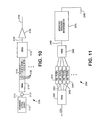
- FIG. 11 is a block diagram of the receive optics of a WDM/TDM multiplexed system.
- a particle motion sensing system 10 according to one embodiment of the present invention is shown in FIG. 1 .
- the particle motion sensing system 10 includes a transducer or sensor 100 , source optics 200 , receive optics 300 , an interferometric interrogator 400 and signal processing/recording electronics 500 .
- FIG. 2A shows an exemplary embodiment for use with narrow band gratings.
- Sensor 100 includes a housing 110 , an optical fiber 130 , a proof mass 150 , and a pretension spring 170 .
- the optical fiber 130 has a free region 132 in which a grating 135 is inscribed.
- the optical fiber 130 is attached at one end to the housing 110 by means of a first anchor 120 and at the other end to the proof mass 150 by means of a second anchor 160 .
- the optical fiber 130 may be attached to the first anchor 120 and the second anchor 160 by bonding or any other suitable method for preventing the optical fiber 130 from slipping relative to either the first anchor 120 or the second anchor 160 .
- Both the first anchor 120 and/or the second anchor 160 may be round spool-shaped structures forming a capstan to help secure the optical fiber 130 to it with the friction therebetween caused by wrapping the optical fiber 130 around the outer diameter of the first anchor 120 or second anchor 160 .
- the proof mass 150 is suspended from the housing 110 by means of a suspension member 180 , a clamping ring 140 , standoffs 145 , and screws 147 .
- Motion of the sensor 100 is identical to motion of the housing 110 .
- Motion of the sensor 100 along a direction 112 results in motion of the housing 110 relative to the proof mass 150 .
- Relative motion between the housing 110 and the proof mass 150 is constrained to occur only in the direction 112 by the suspension member 180 .
- Relative motion between the housing 110 and the proof mass 150 along direction 112 is controlled by the optical fiber 130 and the pretension spring 170 .
- Pretension spring 170 controls the quiescent tension on the optical fiber 130 in conjunction with the mass of the proof mass 150 .
- the force applied between the housing 110 and the proof mass 150 by the pretension spring 170 is controlled by a flexible cantilever 175 and an adjustment screw 177 .
- the flexible cantilever 175 is permanently attached at one end to the housing 110 .
- the suspension member 180 comprises one or more flexible circular membranes or diaphragms fabricated by stamping or forming a flat stock of ductile metal to form a series of concentric waves 185 .
- These waves 185 allow the central region 182 of suspension member 180 to move with little resistance along direction 112 relative to outer portion 183 of suspension member 180 while ensuring central portion 182 and outer portion 183 of suspension member 180 remain parallel when the proof mass 150 is sandwiched between a pair of suspension members 180 .
- motion of the proof mass 150 is allowed along direction 112 , but resisted in all other directions, including rotational motions.
- the grating 135 is created by fabricating two FBGs 1050 , each of which is a periodic change of the refractive index of the glass core 133 of the optical fiber 130 , by means of a laser, a phase mask, an interferometer or other methods well known to practitioners in the art.
- the two FBGs are separated by a small space 1060 on the order of 100 microns.
- the grating 135 ′ can be fabricated as a single grating comprising two halves 1065 and 1070 which are shifted in phase relative to one another, for example by it radians.
- the resulting phase-shifted grating has a typical transmission spectrum 1005 shown in FIG. 4 .
- the significant features of the transmission spectrum 1005 are a central peak 1000 , two stop bands 1010 and two pass bands 1020 .
- Typical values for the spectrum 1005 are a peak transmission width of 0.4 pm, a stop band 1010 depth of >40 dB, stop band 1010 width of about 800 pm and near 100% transmission in the pass bands 1020 .
- Relative motion between the housing 110 and the proof mass 150 changes the longitudinal strain within the free region 132 of optical fiber 130 between the first anchor 120 and the second anchor 160 .
- Changes in the longitudinal strain within the optical fiber 130 cause a proportional shift of the peak wavelength of the reflection or transmission spectrum of the grating 135 .
- the source optics 200 include a broadband optical source 210 , prefilters 220 and an optical amplifier 230 .
- the broadband optical source 210 is a Superluminescent Light Emitting Diode (SLED).
- SLED Superluminescent Light Emitting Diode
- any suitable optical source with a bandwidth of at least approximately 1 nm may be used, such as an Amplified Spontaneous Emission (ASE) source, Light Emitting Diode (LED), etc.
- the source should provide an intensity of at least 0.4 mW/nm into an optical fiber and have a spectral output at least 1 nm wide.
- the output of the broadband optical source 210 is connected to the input of the prefilters 220 through an optical fiber 215 .
- the prefilters 220 may comprise one or more band pass optical filters, each of which has a passband of about 1 nm. Examples of such a filter are a Dense Wavelength Division Multiplexer (DWDM) or an Optical Add Drop Multiplexer (OADM), both of which are well known to those practiced in the art of telecommunication and sensing optics.
- DWDM Dense Wavelength Division Multiplexer
- OADM Optical Add Drop Multiplexer
- the output of the prefilters 220 is connected to the input of the optical amplifier 230 through optical fiber 225 .
- the optical amplifier 230 can be any suitable means for providing optical gain.
- optical amplifiers examples include Erbium-Doped Fiber Amplifiers (EDFAs) and Semiconductor Optical Amplifiers (SOAs), both of which are well known to those practiced in the art of telecommunication and sensing optics.
- EDFAs Erbium-Doped Fiber Amplifiers
- SOAs Semiconductor Optical Amplifiers
- the receive optics 300 include an Amplified Spontaneous Emission (ASE) filter 305 and a mismatched path interferometer 310 .
- the output of the sensor 100 is connected to the input of the ASE filter 305 through an optical fiber 302 .
- the ASE filter 305 is a bandpass filter used to minimize the intensity of amplified spontaneous emission from the optical amplifier 230 that is outside the stop band 1010 of the grating 135 .
- the ASE filter 305 preferably has a very narrow transmission passband.
- An example of an appropriate ASE filter 305 is a 50 GHz OADM.
- ASE filter 305 includes an optical circulator 303 and an FBG 304 .
- the optical circulator 303 is a passive optical device well known within the field of telecommunications that passes light from a first port 309 to second port 308 , but not vice versa. It also passes light from second port 308 to third port 311 , but not vice versa. It also does not pass light from third port 311 to first port 309 . In other words, light can only circulate in and out of the circulator 303 in one direction.
- Connected to output power of the circulator 303 is the FBG 304 .
- the FBG 304 has a high peak reflectivity (>80%) and a full width half maximum bandwidth of about 300 pm. Such devices are well known to those who practice in the art. The distal lead of FBG 304 remains unconnected.
- the mismatched path interferometer 310 includes a 2 ⁇ 2 optical coupler 320 , a phase modulator 330 , an optical delay line 340 and two mirrors 350 .
- the input leg 307 of the 2 ⁇ 2 optical coupler 320 is connected to the output of the ASE filter 305 .
- the 2 ⁇ 2 optical coupler 320 divides the input light with half going to each of its output leads 325 and 337 .
- One output lead 325 is connected to the phase modulator 330 , which is connected to mirror 350 through optical fiber 335 .
- the phase modulator 330 is used to impose a known phase to the light traveling within a leg 370 of the mismatched path interferometer 310 .
- the other output lead 337 of the 2 ⁇ 2 optical coupler 320 is connected to the optical delay line 340 , which is connected to mirror 350 through optical fiber 345 .
- the physical length difference between the leg 370 and a leg 380 of the mismatched path interferometer 310 is non-zero, and is preferably in the range of approximately 1-5 meters.
- the mismatched pathlength interferometer 310 converts the changing peak wavelength in the central peak 1000 of the light transmitted from the sensor 100 into a change in phase angle of the light traversing the two legs 370 and 380 .
- the conversion of the peak wavelength to phase is on the order of 2 rad/pm, and increases with larger differences in length between the two legs 370 and 380 .
- the interferometric interrogator 400 After the light passes through the mismatched pathlength interferometer 310 , it travels by means of output fiber 355 to the interferometric interrogator 400 .
- the function of the interferometric interrogator 400 is to measure the change in the phase angle difference between the two legs 370 and 380 of the mismatched pathlength interferometer 310 over time.
- a number of approaches have been used for interferometric interrogation, such as heterodyne demodulation and homodyne demodulation.
- the Optiphase OPD-4000 is a suitable demodulator. It applies a sinusoidal modulation waveform to the phase modulator 330 .
- An example frequency for the modulation waveform is 20 kHz, well above the planned maximum operational frequency of the system—about 150 Hz.
- the resultant modulated optical waveform that arrives at the interferometric demodulator 400 is converted to an electrical signal, digitized and downconverted within the interferometric demodulator 400 .
- FIG. 8 illustrates a low noise method of measuring the phase angle difference between the two legs 370 and 380 of the mismatched pathlength interferometer 310 over time using a closed loop interferometric interrogator 400 .
- a stable, low noise local oscillator 460 provides a modulation waveform such as a sine wave.
- a bias amplifier 470 adjusts the amplitude of the output of the local oscillator 460 to be applied to the phase modulator 330 .
- a ⁇ /2 radian phase shift is applied to the phase modulator 330 to ensure that the mismatched pathlength interferometer 310 operates within a roughly linear range of its transfer function.
- the interference signal from the mismatched pathlength interferometer 310 travels along optical fiber 411 and illuminates photodetector 410 .
- the purpose of photodetector 410 is to convert light into an electrical current.
- a number of suitable devices are available for photodetector 410 .
- the exemplary embodiment utilizes an ETX-100, manufactured by JDS Uniphase.
- the electrical output of the photodetector 410 is connected to a very low noise, high gain preamplifier 420 .
- the output of the preamplifier 420 is connected to an Automatic Gain Control (AGC) 430 .
- AGC 430 enables continuous correction for changes in optical intensity levels throughout the system.
- the output of AGC 430 is mixed with the signal from the local oscillator 460 within an analog multiplier 440 .
- the purpose of the analog multiplier 440 is to provide a pair of signals equal to the sum and difference of the AGC 430 output and local oscillator 460 .
- the output of the analog multiplier 440 is connected to the input of a low pass filter 450 .
- the cutoff frequency of the low pass filter 450 would be around 500 Hz.
- the cutoff frequency of the low pass filter is well below the sum frequency of the output of the analog multiplier 440 . This ensures only the low frequency difference signal from the analog multiplier 440 is passed.
- the combination of local oscillator 460 , analog multiplier 440 and low pass filter 450 functions as a synchronous detector.
- the output signal from the low pass filter 450 is passed along to a high gain amplifier 455 .
- the output of the high gain amplifier 455 is connected to the input of the variable gain output driver amplifier 495 which provides a voltage output proportional to the phase angle difference between the two legs 370 and 380 of the mismatched pathlength interferometer 310 over time.
- the output voltage of the amplifier 495 is also proportional to the amplitude of the acceleration experienced by the sensor 100 .
- the output of the bias amplifier 470 is added to the output of the high gain amplifier 455 in a summing amplifier 480 .
- the output of the summing amplifier is connected to the input of a modulator driver amplifier 490 .
- the output 491 of the modulator driver amplifier 490 is applied to electrical input 331 of the phase modulator 330 within the mismatched pathlength interferometer 310 ( FIG. 6 ).
- the negative overall loop gain of the interferometric interrogator 400 acts to provide negative feedback to the phase modulator 330 which is equal and opposite to the optical phase angle difference between the two legs 370 and 380 of the mismatched pathlength interferometer 310 . This nulling action serves to maintain operation of the mismatched pathlength interferometer 310 within the linear range of its transfer function.
- SF system SF sensor *SF FBG *SF interferometer
- the overall system scale factor SF system is the product of the sensor scale factor SF sensor , typically 1,000 microstrain/g, the FBG scale factor SFfbg, typically 1.2 pm/microstrain, and the interferometer scale factor SF interferometer , typically about 3 Rad/pm.
- RIN Relative Intensity Noise
- this provides a minimum detectable acceleration of ⁇ 149.5 dB:g or about 33 ng, which is typical performance for electronic, moving coil-type geophones, but about 10,000 times better resolution than FBG accelerometers that employ typical, or spectroscopic-type interrogation.
- FIG. 9 An embodiment of a WDM/TDM multiplexed system 2000 is shown in FIG. 9 .
- This system includes source optics 2100 , which is shown in greater detail in FIG. 10 .
- the output of a broadband optical source 2110 is connected to the input of an optical switch 2113 via an optical fiber 2112 .
- Semiconductor Optical Amplifiers (SOAs) are typical devices suitable for high extinction ratio optical switching. Suitable devices are manufactured by companies such as Inphenix and Kamelian.
- the optical switch 2113 creates a series of pulses needed for interrogation.
- Dense Wavelength Division Multiplexer (DWDM) 2115 divides the light along multiple fibers 2120 , each with a different central wavelength, typically separated by about 0.8 nm.
- DWDM Dense Wavelength Division Multiplexer
- each of the fibers 2120 is added a different fiber optic delay line 2116 , 2117 , 2118 , and 2119 , typically 50 to 100 m.
- the four different wavelengths of light travelling through the delay lines 2116 through 2119 are passed through a second DWDM 2135 , which recombines all four wavelengths and outputs them together along optical fiber 2125 to an optical amplifier 2130 .
- the output of the optical amplifier 2130 passes through optical fiber 2170 .
- the output of the source optics 2100 passes through optical fiber 2170 to the sensor array 2150 .
- the sensor array 2150 consists of a series of sensors and filters in a ladder configuration with one downlink optical fiber and one uplink optical fiber.
- Light travelling from optical fiber 2170 continues along downlink optical fiber 2175 to OADM 2200 .
- OADM 2200 acts to filter out a narrow (on the order of 1 nm wide) wavelength band of light for the first sensor and passes the remainder of the light for the remaining sensors.
- the “drop” leg of OADM 2200 is connected to the input of a sensor 2210 .
- the output of sensor 2210 is connected to the “add” leg of OADM 2250 .
- the “pass” leg of OADM 2250 is connected to the uplink fiber 2255 . The light from the sensor 2210 thus passes along the uplink optical fiber 2255 to the receive optics 2260 .
- the light from the “pass” leg of OADM 2200 is connected to the input of OADM 2220 .
- OADMs 2200 , 2220 , 2320 and 2340 have different add wavelengths.
- OADMs 2200 , 2220 , 2320 and 2340 have different pass wavelengths.
- the “drop” leg of OADM 2220 is connected to a sensor 2230 .
- the output of sensor 2230 is connected to the “add” leg of OADM 2240 .
- the “pass” leg of OADM 2240 is connected to the input leg of OADM 2250 .
- the “pass” leg of OADM 2220 is connected to the input leg of OADM 2320 .
- the “drop” leg of OADM 2320 is connected to the input of a sensor 2325 .
- the output of sensor 2325 is connected to the “add” leg of OADM 2350 .
- the “pass” leg of OADM 2350 is connected to the input leg of OADM 2240 .
- the “pass” leg of OADM 2320 is connected to the input leg of OADM 2340 .
- the “drop” leg of OADM 2340 is connected to the input of sensor 2425 .
- the output of sensor 2425 is connected to the “add” leg of OADM 2450 .
- the “pass” leg of OADM 2450 is connected to the input leg of OADM 2350 .
- the “pass” leg of OADM 2340 and the input leg of OADM 2450 remain unconnected.
- the uplink optical fiber 2255 is connected to the input of DWDM 2400 .
- DWDM 2400 divides the light into four bands, one for each of the sensors 2210 , 2230 , 2325 and 2425 .
- Each output leg of the DWDM 2400 is connected to a respective one of four ASE filters 2410 , 2420 , 2430 and 2440 .
- the ASE filters are identical to ASE filter 305 .
- the outputs of the ASE filters 2410 , 2420 , 2430 and 2440 are connected to the four inputs of DWDM 2460 , which recombines the wavelengths onto a single fiber 2465 .
- Fiber 2465 is connected to the mismatched pathlength interferometer 2470 .
- the output of the mismatched pathlength interferometer 2470 is connected to a fiber 2265 .
- fiber 2265 is connected to TDM demodulator 2300 .
- TDM demodulators are available, such as the ERS-5100 manufactured by Optiphase, Inc., Van Nuys, Calif.
- the TDM demodulator 2300 controls the optical switch 2113 , which provides light pulses to each of the sensors 2210 , 2230 , 2325 and 2425 that are separated in time such that each sensor can be interrogated separately by the same TDM demodulator 2300 .
- the TDM demodulator 2300 also controls the amplitude and phase of the phase modulator within the mismatched pathlength interferometer 2470 , which is identical to the mismatched pathlength interferometer 310 used for a single sensor 100 .
- the output of the TDM demodulator 2300 is a digital representation of the output of each of the sensors 2210 , 2230 , 2325 and 2425 and is input to the signal processing/recording electronics 2500 for further filtering, averaging, storage and display.
Landscapes
- Physics & Mathematics (AREA)
- General Physics & Mathematics (AREA)
- Optical Transform (AREA)
- Length Measuring Devices By Optical Means (AREA)
- Instruments For Measurement Of Length By Optical Means (AREA)
Abstract
Description
SFsystem=SFsensor*SFFBG*SFinterferometer
Where the overall system scale factor SFsystem is the product of the sensor scale factor SFsensor, typically 1,000 microstrain/g, the FBG scale factor SFfbg, typically 1.2 pm/microstrain, and the interferometer scale factor SFinterferometer, typically about 3 Rad/pm. These typical values result in an overall system scale factor of 2,988 rad/g (69.5 dB:Rad/g). The dominant noise source in these types of systems is the Relative Intensity Noise (RIN) caused by the extreme filtering of the broadband
Claims (12)
Priority Applications (2)
| Application Number | Priority Date | Filing Date | Title |
|---|---|---|---|
| US13/190,516 US8240207B2 (en) | 2007-10-16 | 2011-07-26 | Fiber optic particle motion sensor and measuring method using the sensor |
| US13/464,547 US20120216615A1 (en) | 2007-10-16 | 2012-05-04 | Method of measuring acceleration using a fiber optic particle motion sensor |
Applications Claiming Priority (3)
| Application Number | Priority Date | Filing Date | Title |
|---|---|---|---|
| US99924607P | 2007-10-16 | 2007-10-16 | |
| US12/253,161 US7999946B2 (en) | 2007-10-16 | 2008-10-16 | Fiber optic particle motion sensor system |
| US13/190,516 US8240207B2 (en) | 2007-10-16 | 2011-07-26 | Fiber optic particle motion sensor and measuring method using the sensor |
Related Parent Applications (1)
| Application Number | Title | Priority Date | Filing Date |
|---|---|---|---|
| US12/253,161 Division US7999946B2 (en) | 2007-10-16 | 2008-10-16 | Fiber optic particle motion sensor system |
Related Child Applications (1)
| Application Number | Title | Priority Date | Filing Date |
|---|---|---|---|
| US13/464,547 Division US20120216615A1 (en) | 2007-10-16 | 2012-05-04 | Method of measuring acceleration using a fiber optic particle motion sensor |
Publications (2)
| Publication Number | Publication Date |
|---|---|
| US20110277548A1 US20110277548A1 (en) | 2011-11-17 |
| US8240207B2 true US8240207B2 (en) | 2012-08-14 |
Family
ID=43305221
Family Applications (3)
| Application Number | Title | Priority Date | Filing Date |
|---|---|---|---|
| US12/253,161 Active 2029-12-16 US7999946B2 (en) | 2007-10-16 | 2008-10-16 | Fiber optic particle motion sensor system |
| US13/190,516 Active US8240207B2 (en) | 2007-10-16 | 2011-07-26 | Fiber optic particle motion sensor and measuring method using the sensor |
| US13/464,547 Abandoned US20120216615A1 (en) | 2007-10-16 | 2012-05-04 | Method of measuring acceleration using a fiber optic particle motion sensor |
Family Applications Before (1)
| Application Number | Title | Priority Date | Filing Date |
|---|---|---|---|
| US12/253,161 Active 2029-12-16 US7999946B2 (en) | 2007-10-16 | 2008-10-16 | Fiber optic particle motion sensor system |
Family Applications After (1)
| Application Number | Title | Priority Date | Filing Date |
|---|---|---|---|
| US13/464,547 Abandoned US20120216615A1 (en) | 2007-10-16 | 2012-05-04 | Method of measuring acceleration using a fiber optic particle motion sensor |
Country Status (1)
| Country | Link |
|---|---|
| US (3) | US7999946B2 (en) |
Cited By (7)
| Publication number | Priority date | Publication date | Assignee | Title |
|---|---|---|---|---|
| US9441433B2 (en) | 2012-07-27 | 2016-09-13 | Avalon Sciences, Ltd | Remotely actuated clamping devices for borehole seismic sensing systems and methods of operating the same |
| US9582072B2 (en) | 2013-09-17 | 2017-02-28 | Medibotics Llc | Motion recognition clothing [TM] with flexible electromagnetic, light, or sonic energy pathways |
| US10234934B2 (en) | 2013-09-17 | 2019-03-19 | Medibotics Llc | Sensor array spanning multiple radial quadrants to measure body joint movement |
| US10321873B2 (en) | 2013-09-17 | 2019-06-18 | Medibotics Llc | Smart clothing for ambulatory human motion capture |
| US10602965B2 (en) | 2013-09-17 | 2020-03-31 | Medibotics | Wearable deformable conductive sensors for human motion capture including trans-joint pitch, yaw, and roll |
| US10716510B2 (en) | 2013-09-17 | 2020-07-21 | Medibotics | Smart clothing with converging/diverging bend or stretch sensors for measuring body motion or configuration |
| US12352618B2 (en) | 2021-04-12 | 2025-07-08 | Board Of Trustees Of Michigan State University | Demodulation of fiber optic sensors |
Families Citing this family (21)
| Publication number | Priority date | Publication date | Assignee | Title |
|---|---|---|---|---|
| GB9908075D0 (en) | 1999-04-09 | 1999-06-02 | Secr Defence | An optical fibre sensor assembly |
| US7683312B2 (en) | 2007-10-23 | 2010-03-23 | Us Sensor Systems, Inc. | Fiber-optic interrogator with normalization filters |
| GB0810977D0 (en) * | 2008-06-16 | 2008-07-23 | Qinetiq Ltd | Phase based sensing |
| US9194738B2 (en) | 2009-10-23 | 2015-11-24 | Pacific Western Bank | Fiber optic microseismic sensing systems |
| US9158032B2 (en) | 2010-02-18 | 2015-10-13 | US Seismic Systems, Inc. | Optical detection systems and methods of using the same |
| WO2011103271A2 (en) | 2010-02-18 | 2011-08-25 | US Seismic Systems, Inc. | Fiber optic personnel safety systems and methods of using the same |
| US8401354B2 (en) | 2010-02-23 | 2013-03-19 | US Seismic Systems, Inc. | Fiber optic security systems and methods of using the same |
| US8701481B2 (en) | 2010-07-06 | 2014-04-22 | US Seismic Systems, Inc. | Borehole sensing and clamping systems and methods of using the same |
| WO2012103085A2 (en) | 2011-01-25 | 2012-08-02 | US Seismic Systems, Inc. | Light powered communication systems and methods of using the same |
| US8645101B2 (en) * | 2011-02-10 | 2014-02-04 | Siemens Energy, Inc. | Method for monitoring the condition of a vibration sensor |
| US8820167B2 (en) | 2011-02-10 | 2014-09-02 | Siemens Energy, Inc. | Vibration sensor |
| US9217801B2 (en) * | 2011-03-08 | 2015-12-22 | Pacific Western Bank | Fiber optic acoustic sensor arrays and systems, and methods of fabricating the same |
| JP5118246B1 (en) * | 2011-11-25 | 2013-01-16 | 白山工業株式会社 | Optical fiber sensor |
| US8670124B2 (en) * | 2012-01-31 | 2014-03-11 | Nokia Corporation | Apparatus and method for converting sensor input signals into digital output signals |
| JP6159095B2 (en) * | 2013-02-05 | 2017-07-05 | 株式会社Subaru | Displacement measuring device and displacement measuring method |
| US9684012B2 (en) | 2014-06-19 | 2017-06-20 | Avalon Sciences Ltd | Damped fiber optic accelerometers, sensors, and sensor assemblies, and methods of assembling the same |
| US9885592B2 (en) | 2014-07-14 | 2018-02-06 | Avalon Sciences Ltd. | Fiber optic backscatter sensing systems and methods of operating the same |
| US9594093B2 (en) * | 2014-12-15 | 2017-03-14 | Intel Corporation | Apparatus, method, and system for detecting acceleration and motor monitoring |
| US9448312B1 (en) | 2015-03-11 | 2016-09-20 | Baker Hughes Incorporated | Downhole fiber optic sensors with downhole optical interrogator |
| EP3829826B1 (en) * | 2018-08-01 | 2024-02-21 | Intuitive Surgical Operations, Inc. | Systems and methods for controlling a robotic manipulator or associated tool |
| CN113325464A (en) * | 2021-05-24 | 2021-08-31 | 西安石油大学 | Grid-mesh type fiber bragg grating acceleration seismic detector |
Citations (11)
| Publication number | Priority date | Publication date | Assignee | Title |
|---|---|---|---|---|
| US5011262A (en) | 1990-04-16 | 1991-04-30 | Litton Systems, Inc. | Fiber optic sensor array |
| US5227857A (en) | 1991-04-24 | 1993-07-13 | The United States Of America As Represented By The Secretary Of The Navy | System for cancelling phase noise in an interferometric fiber optic sensor arrangement |
| US5397891A (en) | 1992-10-20 | 1995-03-14 | Mcdonnell Douglas Corporation | Sensor systems employing optical fiber gratings |
| US5680489A (en) | 1996-06-28 | 1997-10-21 | The United States Of America As Represented By The Secretary Of The Navy | Optical sensor system utilizing bragg grating sensors |
| US5986749A (en) | 1997-09-19 | 1999-11-16 | Cidra Corporation | Fiber optic sensing system |
| US6104492A (en) | 1999-02-22 | 2000-08-15 | Lucent Technologies Inc | Optical signal monitor for multiwave optical signals |
| US6281976B1 (en) * | 1997-04-09 | 2001-08-28 | The Texas A&M University System | Fiber optic fiber Fabry-Perot interferometer diaphragm sensor and method of measurement |
| US6381048B1 (en) | 1998-09-15 | 2002-04-30 | Lucent Technologies Inc. | Wavelength division multiplexed system having reduced cross-phase modulation |
| US20030145654A1 (en) * | 1999-10-01 | 2003-08-07 | Sverre Knudsen | Highly sensitive accelerometer |
| US6819812B2 (en) | 2001-10-26 | 2004-11-16 | Lake Shore Cryotronics, Inc. | System and method for measuring physical, chemical and biological stimuli using vertical cavity surface emitting lasers with integrated tuner |
| US20050097955A1 (en) * | 1999-10-01 | 2005-05-12 | Arne Berg | Highly sensitive accelerometer |
-
2008
- 2008-10-16 US US12/253,161 patent/US7999946B2/en active Active
-
2011
- 2011-07-26 US US13/190,516 patent/US8240207B2/en active Active
-
2012
- 2012-05-04 US US13/464,547 patent/US20120216615A1/en not_active Abandoned
Patent Citations (11)
| Publication number | Priority date | Publication date | Assignee | Title |
|---|---|---|---|---|
| US5011262A (en) | 1990-04-16 | 1991-04-30 | Litton Systems, Inc. | Fiber optic sensor array |
| US5227857A (en) | 1991-04-24 | 1993-07-13 | The United States Of America As Represented By The Secretary Of The Navy | System for cancelling phase noise in an interferometric fiber optic sensor arrangement |
| US5397891A (en) | 1992-10-20 | 1995-03-14 | Mcdonnell Douglas Corporation | Sensor systems employing optical fiber gratings |
| US5680489A (en) | 1996-06-28 | 1997-10-21 | The United States Of America As Represented By The Secretary Of The Navy | Optical sensor system utilizing bragg grating sensors |
| US6281976B1 (en) * | 1997-04-09 | 2001-08-28 | The Texas A&M University System | Fiber optic fiber Fabry-Perot interferometer diaphragm sensor and method of measurement |
| US5986749A (en) | 1997-09-19 | 1999-11-16 | Cidra Corporation | Fiber optic sensing system |
| US6381048B1 (en) | 1998-09-15 | 2002-04-30 | Lucent Technologies Inc. | Wavelength division multiplexed system having reduced cross-phase modulation |
| US6104492A (en) | 1999-02-22 | 2000-08-15 | Lucent Technologies Inc | Optical signal monitor for multiwave optical signals |
| US20030145654A1 (en) * | 1999-10-01 | 2003-08-07 | Sverre Knudsen | Highly sensitive accelerometer |
| US20050097955A1 (en) * | 1999-10-01 | 2005-05-12 | Arne Berg | Highly sensitive accelerometer |
| US6819812B2 (en) | 2001-10-26 | 2004-11-16 | Lake Shore Cryotronics, Inc. | System and method for measuring physical, chemical and biological stimuli using vertical cavity surface emitting lasers with integrated tuner |
Cited By (7)
| Publication number | Priority date | Publication date | Assignee | Title |
|---|---|---|---|---|
| US9441433B2 (en) | 2012-07-27 | 2016-09-13 | Avalon Sciences, Ltd | Remotely actuated clamping devices for borehole seismic sensing systems and methods of operating the same |
| US9582072B2 (en) | 2013-09-17 | 2017-02-28 | Medibotics Llc | Motion recognition clothing [TM] with flexible electromagnetic, light, or sonic energy pathways |
| US10234934B2 (en) | 2013-09-17 | 2019-03-19 | Medibotics Llc | Sensor array spanning multiple radial quadrants to measure body joint movement |
| US10321873B2 (en) | 2013-09-17 | 2019-06-18 | Medibotics Llc | Smart clothing for ambulatory human motion capture |
| US10602965B2 (en) | 2013-09-17 | 2020-03-31 | Medibotics | Wearable deformable conductive sensors for human motion capture including trans-joint pitch, yaw, and roll |
| US10716510B2 (en) | 2013-09-17 | 2020-07-21 | Medibotics | Smart clothing with converging/diverging bend or stretch sensors for measuring body motion or configuration |
| US12352618B2 (en) | 2021-04-12 | 2025-07-08 | Board Of Trustees Of Michigan State University | Demodulation of fiber optic sensors |
Also Published As
| Publication number | Publication date |
|---|---|
| US20100313658A1 (en) | 2010-12-16 |
| US20110277548A1 (en) | 2011-11-17 |
| US20120216615A1 (en) | 2012-08-30 |
| US7999946B2 (en) | 2011-08-16 |
Similar Documents
| Publication | Publication Date | Title |
|---|---|---|
| US8240207B2 (en) | Fiber optic particle motion sensor and measuring method using the sensor | |
| US5680489A (en) | Optical sensor system utilizing bragg grating sensors | |
| Hill et al. | Fiber laser hydrophone array | |
| AU2009226942B2 (en) | Self-referenced optical fibre sensor and related sensor network | |
| US6496264B1 (en) | Fiber optic acoustic sensor with specifically selected flexural disks | |
| US10401377B2 (en) | Optical sensor system and methods of use thereof | |
| Yu et al. | Acoustic measurements using a fiber optic sensor system | |
| Marin et al. | Integrated FBG sensors interrogation using active phase demodulation on a silicon photonic platform | |
| JP2009512199A (en) | Method and apparatus for suppressing laser phase noise | |
| CA2387944A1 (en) | Optical method for the transmission of signals from remote arrays of electrical sensors | |
| Cranch et al. | Fiber laser sensors: Enabling the next generation of miniaturized, wideband marine sensors | |
| US5061069A (en) | Fiber-optic bender beam interferometer accelerometer | |
| Geib | Multiplexing of Extrinsic Fabry-Perot Optical Fiber Sensors for Strain Measurements | |
| El-Gammal et al. | Strain sensing in underwater acoustics with a hybrid π-shifted FBG and different interrogation methods | |
| KR100496554B1 (en) | Optical sensor system using Bragg grating sensor | |
| Vohra et al. | Fiber optic interferometric accelerometers | |
| Jiang | Four-element fiber Bragg grating acceleration sensor array | |
| Vohra et al. | An hybrid WDM/TDM reflectometric array | |
| Ibrahim et al. | PIC based FBG interrogator designed for high accuracy and low noise seismic and dynamic measurements | |
| Cranch | Fiber Multiplexing Principles | |
| He et al. | High performance distributed feedback fiber laser sensor array system | |
| Chang | Effects of fiber Bragg grating spectrum distortion on scanning Fabry-Perot and fiber interferometer based wavelength shift detection schemes | |
| CA2259184C (en) | Optical sensor system utilizing bragg grating sensors | |
| Daxini et al. | Remote fiber optic strain sensing with π-shifted fiber Bragg gratings | |
| Luo et al. | Research on all polarization-maintaining fiber optic accelerometer |
Legal Events
| Date | Code | Title | Description |
|---|---|---|---|
| AS | Assignment |
Owner name: US SENSOR SYSTEMS, INC., CALIFORNIA Free format text: ASSIGNMENT OF ASSIGNORS INTEREST;ASSIGNORS:ANDERSEN, JAMES K.;GOLDNER, ERIC LEE;LAM, LEO;AND OTHERS;SIGNING DATES FROM 20081111 TO 20081112;REEL/FRAME:026837/0987 Owner name: US SEISMIC SYSTEMS, INC., CALIFORNIA Free format text: CHANGE OF NAME;ASSIGNOR:US SENSOR SYSTEMS, INC.;REEL/FRAME:026837/0227 Effective date: 20110502 |
|
| STCF | Information on status: patent grant |
Free format text: PATENTED CASE |
|
| AS | Assignment |
Owner name: SQUARE 1 BANK, NORTH CAROLINA Free format text: SECURITY INTEREST;ASSIGNOR:US SEISMIC SYSTEMS, INC.;REEL/FRAME:034594/0651 Effective date: 20141217 |
|
| AS | Assignment |
Owner name: SQUARE 1 BANK, NORTH CAROLINA Free format text: ASSIGNMENT OF ASSIGNORS INTEREST;ASSIGNOR:SQUARE 1 BANK;REEL/FRAME:036668/0438 Effective date: 20150928 |
|
| AS | Assignment |
Owner name: SQUARE 1 BANK, NORTH CAROLINA Free format text: ASSIGNMENT OF ASSIGNORS INTEREST;ASSIGNORS:US SEISMIC SYSTEMS, INC.;SQUARE 1 BANK;REEL/FRAME:036679/0009 Effective date: 20150928 |
|
| AS | Assignment |
Owner name: SQUARE 1 BANK, NORTH CAROLINA Free format text: CORRECTIVE ASSIGNMENT TO CORRECT THE APPLICATION NUMBER 61682795 AND REPLACE IT WITH APPLICATION NUMBER 13981162 PREVIOUSLY RECORDED ON REEL 036679 FRAME 0009. ASSIGNOR(S) HEREBY CONFIRMS THE ASSIGNMENT;ASSIGNORS:SQUARE 1 BANK;US SEISMIC SYSTEMS, INC.;REEL/FRAME:036827/0724 Effective date: 20150928 Owner name: SQUARE 1 BANK, NORTH CAROLINA Free format text: CORRECTIVE ASSIGNMENT TO CORRECT THE APPLICATION NUMBER 61682795 AND REPLACE IT WITH APPLICATION NUMBER 13981162 PREVIOUSLY RECORDED ON REEL 036668 FRAME 0438. ASSIGNOR(S) HEREBY CONFIRMS THE ASSIGNMENT;ASSIGNOR:SQUARE 1 BANK;REEL/FRAME:036827/0742 Effective date: 20150928 |
|
| REMI | Maintenance fee reminder mailed | ||
| AS | Assignment |
Owner name: PACIFIC WESTERN BANK, CALIFORNIA Free format text: MERGER;ASSIGNOR:SQUARE 1 BANK;REEL/FRAME:038643/0391 Effective date: 20151006 |
|
| AS | Assignment |
Owner name: AVALON SCIENCES LTD, UNITED KINGDOM Free format text: ASSIGNMENT OF ASSIGNORS INTEREST;ASSIGNOR:PACIFIC WESTERN BANK;REEL/FRAME:038678/0925 Effective date: 20160304 |
|
| FPAY | Fee payment |
Year of fee payment: 4 |
|
| SULP | Surcharge for late payment | ||
| MAFP | Maintenance fee payment |
Free format text: PAYMENT OF MAINTENANCE FEE, 8TH YR, SMALL ENTITY (ORIGINAL EVENT CODE: M2552); ENTITY STATUS OF PATENT OWNER: SMALL ENTITY Year of fee payment: 8 |
|
| MAFP | Maintenance fee payment |
Free format text: PAYMENT OF MAINTENANCE FEE, 12TH YR, SMALL ENTITY (ORIGINAL EVENT CODE: M2553); ENTITY STATUS OF PATENT OWNER: SMALL ENTITY Year of fee payment: 12 |