US8234923B2 - Systems and methods for ultrasound imaging - Google Patents
Systems and methods for ultrasound imaging Download PDFInfo
- Publication number
- US8234923B2 US8234923B2 US12/950,341 US95034110A US8234923B2 US 8234923 B2 US8234923 B2 US 8234923B2 US 95034110 A US95034110 A US 95034110A US 8234923 B2 US8234923 B2 US 8234923B2
- Authority
- US
- United States
- Prior art keywords
- image
- ultrasound
- signals
- data
- signal
- Prior art date
- Legal status (The legal status is an assumption and is not a legal conclusion. Google has not performed a legal analysis and makes no representation as to the accuracy of the status listed.)
- Expired - Lifetime, expires
Links
Images


Classifications
-
- G—PHYSICS
- G01—MEASURING; TESTING
- G01S—RADIO DIRECTION-FINDING; RADIO NAVIGATION; DETERMINING DISTANCE OR VELOCITY BY USE OF RADIO WAVES; LOCATING OR PRESENCE-DETECTING BY USE OF THE REFLECTION OR RERADIATION OF RADIO WAVES; ANALOGOUS ARRANGEMENTS USING OTHER WAVES
- G01S15/00—Systems using the reflection or reradiation of acoustic waves, e.g. sonar systems
- G01S15/88—Sonar systems specially adapted for specific applications
- G01S15/89—Sonar systems specially adapted for specific applications for mapping or imaging
-
- A—HUMAN NECESSITIES
- A61—MEDICAL OR VETERINARY SCIENCE; HYGIENE
- A61B—DIAGNOSIS; SURGERY; IDENTIFICATION
- A61B8/00—Diagnosis using ultrasonic, sonic or infrasonic waves
- A61B8/08—Clinical applications
-
- A—HUMAN NECESSITIES
- A61—MEDICAL OR VETERINARY SCIENCE; HYGIENE
- A61B—DIAGNOSIS; SURGERY; IDENTIFICATION
- A61B8/00—Diagnosis using ultrasonic, sonic or infrasonic waves
- A61B8/44—Constructional features of the ultrasonic, sonic or infrasonic diagnostic device
- A61B8/4483—Constructional features of the ultrasonic, sonic or infrasonic diagnostic device characterised by features of the ultrasound transducer
-
- G—PHYSICS
- G01—MEASURING; TESTING
- G01S—RADIO DIRECTION-FINDING; RADIO NAVIGATION; DETERMINING DISTANCE OR VELOCITY BY USE OF RADIO WAVES; LOCATING OR PRESENCE-DETECTING BY USE OF THE REFLECTION OR RERADIATION OF RADIO WAVES; ANALOGOUS ARRANGEMENTS USING OTHER WAVES
- G01S15/00—Systems using the reflection or reradiation of acoustic waves, e.g. sonar systems
- G01S15/88—Sonar systems specially adapted for specific applications
- G01S15/89—Sonar systems specially adapted for specific applications for mapping or imaging
- G01S15/8906—Short-range imaging systems; Acoustic microscope systems using pulse-echo techniques
- G01S15/8977—Short-range imaging systems; Acoustic microscope systems using pulse-echo techniques using special techniques for image reconstruction, e.g. FFT, geometrical transformations, spatial deconvolution, time deconvolution
-
- G—PHYSICS
- G01—MEASURING; TESTING
- G01S—RADIO DIRECTION-FINDING; RADIO NAVIGATION; DETERMINING DISTANCE OR VELOCITY BY USE OF RADIO WAVES; LOCATING OR PRESENCE-DETECTING BY USE OF THE REFLECTION OR RERADIATION OF RADIO WAVES; ANALOGOUS ARRANGEMENTS USING OTHER WAVES
- G01S15/00—Systems using the reflection or reradiation of acoustic waves, e.g. sonar systems
- G01S15/88—Sonar systems specially adapted for specific applications
- G01S15/89—Sonar systems specially adapted for specific applications for mapping or imaging
- G01S15/8906—Short-range imaging systems; Acoustic microscope systems using pulse-echo techniques
- G01S15/8995—Combining images from different aspect angles, e.g. spatial compounding
-
- G—PHYSICS
- G01—MEASURING; TESTING
- G01S—RADIO DIRECTION-FINDING; RADIO NAVIGATION; DETERMINING DISTANCE OR VELOCITY BY USE OF RADIO WAVES; LOCATING OR PRESENCE-DETECTING BY USE OF THE REFLECTION OR RERADIATION OF RADIO WAVES; ANALOGOUS ARRANGEMENTS USING OTHER WAVES
- G01S7/00—Details of systems according to groups G01S13/00, G01S15/00, G01S17/00
- G01S7/52—Details of systems according to groups G01S13/00, G01S15/00, G01S17/00 of systems according to group G01S15/00
- G01S7/52017—Details of systems according to groups G01S13/00, G01S15/00, G01S17/00 of systems according to group G01S15/00 particularly adapted to short-range imaging
- G01S7/52046—Techniques for image enhancement involving transmitter or receiver
- G01S7/52049—Techniques for image enhancement involving transmitter or receiver using correction of medium-induced phase aberration
-
- G—PHYSICS
- G01—MEASURING; TESTING
- G01S—RADIO DIRECTION-FINDING; RADIO NAVIGATION; DETERMINING DISTANCE OR VELOCITY BY USE OF RADIO WAVES; LOCATING OR PRESENCE-DETECTING BY USE OF THE REFLECTION OR RERADIATION OF RADIO WAVES; ANALOGOUS ARRANGEMENTS USING OTHER WAVES
- G01S7/00—Details of systems according to groups G01S13/00, G01S15/00, G01S17/00
- G01S7/52—Details of systems according to groups G01S13/00, G01S15/00, G01S17/00 of systems according to group G01S15/00
- G01S7/52017—Details of systems according to groups G01S13/00, G01S15/00, G01S17/00 of systems according to group G01S15/00 particularly adapted to short-range imaging
- G01S7/52085—Details related to the ultrasound signal acquisition, e.g. scan sequences
- G01S7/5209—Details related to the ultrasound signal acquisition, e.g. scan sequences using multibeam transmission
-
- G—PHYSICS
- G01—MEASURING; TESTING
- G01S—RADIO DIRECTION-FINDING; RADIO NAVIGATION; DETERMINING DISTANCE OR VELOCITY BY USE OF RADIO WAVES; LOCATING OR PRESENCE-DETECTING BY USE OF THE REFLECTION OR RERADIATION OF RADIO WAVES; ANALOGOUS ARRANGEMENTS USING OTHER WAVES
- G01S15/00—Systems using the reflection or reradiation of acoustic waves, e.g. sonar systems
- G01S15/88—Sonar systems specially adapted for specific applications
- G01S15/89—Sonar systems specially adapted for specific applications for mapping or imaging
- G01S15/8906—Short-range imaging systems; Acoustic microscope systems using pulse-echo techniques
- G01S15/8993—Three dimensional imaging systems
Definitions
- the intrinsic resolution of a detector can be expressed as depending on the ratio of the operating wavelength of the signal to the effective dimension of the detector (commonly referred to as a Rayleigh or Sparrow criteria).
- reducing the wavelength (increasing the frequency) and/or increasing the effective dimension of the detector can improve the resolution.
- such a change can be accompanied by undesired effects. For example, an increased frequency signal has a smaller penetration depth in ultrasound applications.
- the present teachings relate to a method of imaging an object in a medium with ultrasound.
- the method includes transmitting acoustic energy from a transmitter to the object such that the acoustic energy becomes scattered.
- the method further includes receiving the scattered energy at a plurality of receivers so as to produce respective analog echo signals.
- the method further includes sampling the analog echo signals at a frequency of F, with each of the sampled analog echo signals includes substantial spectral frequency components above a frequency of F/2 and includes substantial nonnegative spectral frequency components below or at said frequency of F/2. Such sampling produces a respective plurality of digital echo signals.
- the substantial spectral frequency components above a frequency of F/2 include a higher frequency having an intensity that is above a predetermined value.
- a predetermined value can have different values, such as 50 dB, 40 dB, 30 dB, 20 dB, 10 dB, or 10 dB less than a maximum intensity of the spectral frequency components of one of the sampled analog echo signals.
- the step of combining the plurality of digital echo signals further includes assigning one of the plurality of combinations having a particular quality value to a scanline for the first receiver.
- the selected time window corresponds to a layer having a first thickness along the scanline.
- the particular quality value includes a running average of an amplitude of the one of the plurality of combinations.
- the particular quality value includes a slope of a running average of an amplitude with respect to time of the one of the plurality of combinations.
- the step of combining the plurality of digital echo signals further includes splitting a parent layer into two or more sublayers and performing time-shift combinations on each of the sublayers.
- the step further includes determining a best quality value for each of the sublayers.
- the step further includes comparing a best quality value of the parent layer to the best quality value of each of the sublayers. If the best quality value of the parent layer is substantially less than the best quality value of each of the sublayers, then the step further includes continuing to divide each of the sublayers into final sublayers, where each of the best quality values of the final sublayers is less than the best quality value of a parent layer of the final sublayers.
- the step further includes assigning a combined digital signal of the parent layer of the final sublayers to the scanline.
- combining of the plurality of digital echo signals substantially negates the effects, of aliasing within at least the sampled analog echo signals.
- the processor further facilitates production of a plurality of image pixels from the plurality of different combinations of the plurality of digital echo signals.
- the plurality of pixels distinctly depict two objects in the medium that are closer together than 4F divided into an average velocity of sound in the medium.
- such an apparatus can distinctly depict two objects in the medium that are closer together than approximately 100 micrometers when the acoustic energy has a central peak frequency of approximately 3.5 MHz.
- the acoustic energy propagates in the medium with an average velocity of approximately 1540 m/s.
- the substantial spectral frequency components above a frequency of F/2 include a higher frequency having an intensity that is above a predetermined value.
- a predetermined value can have different values, such as 50 dB, 40 dB, 30 dB, 20 dB, 10 dB, or 10 dB less than a maximum intensity of the spectral frequency components of one of the sampled analog echo signals.
- the process further includes splitting a parent layer into two or more sublayers, and performing time-shift combinations on each of the sublayers.
- the process further includes determining a best quality value for each of the sublayers.
- the process further includes comparing a best quality value of the parent layer to the best quality value of each of the sublayers. If the best quality value of the parent layer is substantially less than the best quality value of each of the sublayers, then the process continues to divide each of the sublayers into final sublayers. Each of the best quality values of the final sublayers is less than the best quality value of a parent layer of the final sublayers.
- the present teachings relate to an ultrasound imaging apparatus that includes a transducer assembly having a plurality of transmitting elements and a plurality of receiving elements.
- the plurality of transmitting elements are configured to transmit ultrasound energy, having a wavelength ⁇ corresponding to a central peak frequency of the ultrasound energy, toward a region in a medium.
- the plurality of receiver elements generate a plurality of signals in response to scattered energy from the region.
- An aperture size D of the transducer assembly is the maximum distance between any two receiving elements in the transducer assembly.
- the apparatus further includes a processor configured to sample the plurality of signals to produce a plurality of corresponding digital echo signals.
- the process further includes assigning one of the plurality of combinations having a particular quality value to a scanline for the first receiver.
- the selected time window corresponds to a layer having a first thickness along the scanline.
- the particular quality value includes a running average of an amplitude of the one of the plurality of combinations.
- the particular quality value includes a slope of a running average of an amplitude with respect to time of the one of the plurality of combinations.
- the process further includes assigning a combined digital signal of the parent layer of the final sublayers to the scanline.
- the scanline is divided into a plurality of layers, and determinations of the particular qualities of the combinations are performed successively starting from a layer closest to the receiver.
- the spatial resolution limit allows resolving of the two objects in the medium that are closer together than approximately 100 micrometers when the ultrasound energy has a central peak frequency of approximately 3.5 MHz.
- the acoustic energy propagates in the medium with an average velocity of approximately 1540 m/s.
- the step of digitally combining the signals includes digitally sampling the signals so as to produce a plurality of digital echo signals.
- the step further includes selecting a first digital echo signal associated with a first receiver.
- the step further includes performing a plurality of time-shift combinations of the first digital echo signal with one or more digital echo signals associated with one or more other receivers about a selected time window of the first signal. Each of the plurality of combinations has a quality value indicative of a quality of the combination.
- the step of digitally combining the signals further includes assigning one of the plurality of combinations having a particular quality value to a scanline for the first receiver.
- the selected time window corresponds to a layer having a first thickness along the scanline.
- the particular quality value includes a running average of an amplitude of the one of the plurality of combinations.
- the particular quality value includes a slope of a running average of an amplitude with respect to time of the one of the plurality of combinations.
- the scanline is divided into a plurality of layers, and determinations of the particular qualities of the combinations are performed successively starting from a layer closest to the receiver.
- the present teachings relate to an ultrasound imaging apparatus having a plurality of transmitters configured to transmit acoustic energy to an object in a medium such that the acoustic energy becomes scattered.
- the apparatus further includes a plurality of receivers configured to receive the scattered energy and in response produce respective analog echo signals.
- the apparatus further includes a sampling module configured to sample the analog echo signals at a frequency of F.
- Each of the sampled analog echo signals includes substantial spectral frequency components above a frequency of F/2 and includes substantial nonnegative spectral frequency components below or at the frequency of F/2.
- the sampling produces a respective plurality of digital echo signals.
- the apparatus further includes a combining module configured to combine the plurality of digital echo signals.
- the substantial spectral frequency components above a frequency of F/2 include a higher frequency having an intensity that is above a predetermined value.
- the predetermined value is 50 dB less than a maximum intensity of the spectral frequency components of one of the sampled analog echo signals.
- the predetermined value is 40 dB less than a maximum intensity of the spectral frequency components of one of the sampled analog echo signals.
- the predetermined value is 30 dB less than a maximum intensity of the spectral frequency components of one of the sampled analog echo signals.
- the predetermined value is 20 dB less than a maximum intensity of the spectral frequency components of one of the sampled analog echo signals.
- the scanline is divided into a plurality of layers. Determinations of the particular qualities of the combinations are performed successively starting from a layer closest to the receiver.
- combining of the plurality of digital echo signals substantially negates the effects of aliasing within at least the sampled analog echo signals.
- One embodiment of the present disclosure relates to an ultrasound imaging apparatus that includes a sampling module configured to sample, at a frequency of F, a plurality of analog echo signals received from a respective plurality of receivers.
- Each of the sampled analog echo signals includes substantial spectral frequency components above a frequency of F/2 and includes substantial nonnegative spectral frequency components below or at the frequency of F/2.
- the sampling produces a respective plurality of digital echo signals.
- the apparatus further includes a combining module configured to combine the plurality of digital echo signals.
- Each of the digital echo signals is offset by time with respect to another of the digital echo signals, so as to produce a combined digital signal that is selected from a plurality of different combinations of the plurality of digital echo signals.
- the apparatus further includes an image-producing module configured to produce an image pixel of an object from the combined digital signal.
- One embodiment of the present disclosure relates to an ultrasound imaging apparatus having a plurality of means for sampling, with each means for sampling configured to sample, at a frequency of F, an analog echo signal received from a receiver.
- Each of the sampled analog echo signals includes substantial spectral frequency components above a frequency of F/2 and includes substantial nonnegative spectral frequency components below or at the frequency of F/2.
- the plurality of means for sampling produces a respective plurality of digital echo signals.
- the apparatus further includes means for combining the plurality of digital echo signals, with each of the digital echo signals being offset by time with respect to another of the digital echo signals, so as to produce a combined digital signal that is selected from a plurality of different combinations of the plurality of digital echo signals.
- the apparatus further includes means for producing an image pixel of an object from the combined digital signal.
- the apparatus further includes a combining module configured to combine said plurality of digital echo signals, with each of said digital echo signals being offset by time with respect to another of said digital echo signals, so as to produce a combined digital signal that is selected from a plurality of different combinations of said plurality of digital echo signals.
- the apparatus further includes an image producing module configured to produce an image pixel of said object from said combined digital signal.
- Each of the plurality of first indices represents a travel time of the acoustic energy along an assumed path from a transmitter to a voxel in a proposed image plane and from the voxel to a receiver.
- the processing module is further configured so as to produce a first set of object data by combining first selected portions of the digitized signals. Each of the first selected portions is determined based on the plurality of first indices.
- the processing module is further configured so as to determine a location of a skin surface of the anatomy.
- the skin surface represents a scattering interface.
- the processing module is further configured so as to calculate a plurality of second indices for the voxels in the proposed image plane.
- the voxels are located on the opposite side of the skin surface with respect to the plurality of transmitters.
- Each of the plurality of second indices is determined by an adjustment to at least one of the plurality of first indices due to refraction of the acoustic energy at the scattering interface. The adjustment is determined based on assumed sound speeds in the coupling medium and in the tissue between the scattering interface and the object.
- the processing module is further configured so as to produce a second set of object data by combining second selected portions of the digitized signals. Each of the second selected portions determined based on the plurality of second indices.
- the tissue includes a human breast.
- the processing module is further configured to re-calculate the plurality of second indices and re-produce the second set of object data by obtaining an optimized focus while varying the speed of sound between the scattering interface and the object.
- the optimized focus includes a maximized contrast in a boundary or a reflector within the tissue.
- the processing module is further configured to calculate a plurality of additional indices and produce one or more additional sets of object data corresponding to a plurality of layers within the tissue between the scattering interface and the object.
- the refraction is determined in three dimensions.
- At least one of the plurality of transmitters includes a transducer or a point source that is virtual, having been created by the timed firing of part or all of an array of physical transducers.
- the apparatus further includes an image producing module that produces an image of the object based on the second set of object data.
- the signal processing component can include, for example, an analog-to-digital converter (ADC).
- ADC analog-to-digital converter
- the processing module can include one or more devices, one or more processes, or any combination thereof.
- the processing module can also include one or more hardware components, one or more software components, or any combination thereof.
- the image producing module can include one or more devices, one or more processes, or any combination thereof, and can include a still-image generating device, a video-image generating device, or any combination thereof.
- the image producing module can also include one or more hardware components, one or more software components, or any combination thereof.
- any combination of the signal processing component, processing module, and/or image producing module can be part of a single component, or be part of a plurality of components.
- the image producing module and the processing module form a single component.
- the single component also includes the signal processing component.
- One embodiment of the present disclosure relates to an ultrasound apparatus that includes a plurality of transmitters configured to transmit acoustic energy to a tissue of an animal having an anatomy through a coupling medium, such that the acoustic energy becomes scattered by an object in the tissue.
- the apparatus further includes a plurality of receivers configured to receive the scattered energy and produce respective analog echo signals.
- the apparatus further includes a signal processing component configured to digitize the analog echo signals so as to produce respective digitized signals.
- the apparatus further includes a processing module configured so as to estimate a tissue configuration, including positions of one or more boundaries between a plurality of regions and speeds of sound in each of the plurality of regions. Each of the plurality of regions has a thickness.
- the processing module is further configured so as to calculate a plurality of indices.
- the tissue includes a human liver.
- the signal processing component and the processing module form a single component.
- the processing module is configured to make use of a previous estimation of a tissue configuration including positions of one or more boundaries between a plurality of regions and speeds of sound in each of the plurality of regions, with each of the plurality of regions having a thickness.
- the signal processing component can include, for example, an analog-to-digital converter (ADC).
- ADC analog-to-digital converter
- the processing module can include one or more devices, one or more processes, or any combination thereof.
- the processing module can also include one or more hardware components, one or more software components, or any combination thereof.
- the image producing module can include one or more devices, one or more processes, or any combination thereof, and can include a still-image generating device, a video-image generating device, or any combination thereof.
- the image producing module can also include one or more hardware components, one or more software components, or any combination thereof.
- any combination of the signal processing component, processing module, and/or image producing module can be part of a single component, or be part of a plurality of components.
- One embodiment of the present disclosure relates to an ultrasound apparatus that includes a plurality of transmitters configured to transmit acoustic energy to a tissue of an animal having an anatomy through a coupling medium, such that the acoustic energy becomes scattered by an object in the tissue.
- the apparatus further includes a plurality of receivers configured to receive the scattered energy and produce respective analog echo signals.
- the apparatus further includes a signal processing component configured to digitize the analog echo signals so as to produce respective digitized signals.
- the apparatus further includes a processing module configured so as to calculate a plurality of indices. Each of the plurality of indices represents a travel time of the acoustic energy from a transmitter to a voxel in a proposed image plane and from the voxel to a receiver.
- the signal processing component can include, for example, an analog-to-digital converter (ADC).
- ADC analog-to-digital converter
- the processing module can include one or more devices, one or more processes, or any combination thereof.
- the processing module can also include one or more hardware components, one or more software components, or any combination thereof.
- any combination of the signal processing component, and/or processing module can be part of a single component, or be part of a plurality of components.
- the processing module is further configured so as to calculate a plurality of adjustments to the plurality of indices based on refraction across the first interface.
- the processing module is further configured so as to obtain an optimized focus in the second layer while varying the speed of sound in the second layer.
- the signal processing component can include, for example, an analog-to-digital converter (ADC).
- ADC analog-to-digital converter
- the processing module can include one or more devices, one or more processes, or any combination thereof.
- the processing module can also include one or more hardware components, one or more software components, or any combination thereof.
- any combination of the signal processing component and/or processing module can be part of a single component, or be part of a plurality of components.
- the apparatus includes a plurality of transmitters configured to transmit acoustic energy to a tissue of an animal having an anatomy through a coupling medium, such that the acoustic energy becomes scattered by an object in the tissue.
- the apparatus further includes a plurality of receivers configured to receive the scattered energy and produce respective analog echo signals.
- the apparatus further includes a signal processing component configured to digitize the analog echo signals so as to produce respective digitized signals.
- the apparatus further includes a processing module configured so as to calculate a plurality of first indices.
- Each of the plurality of first indices represents a travel time of the acoustic energy along an assumed path from a transmitter to a voxel in the tissue and from the voxel to a receiver. The travel time is determined based on an estimated speed of sound in the tissue.
- the processing module is further configured so as to produce a first set of object data by combining first selected portions of the digitized signals. Each of the first selected portions is determined based on the first indices.
- the processing module is further configured so as to determine a location of one or more interfaces based on the first set of object data. The one or more interfaces define regions of interest in the tissue.
- the processing module is further configured so as to calculate plurality of second indices for voxels in the regions of interest.
- One embodiment of the present disclosure relates to a method of imaging a portion of anatomy with ultrasound.
- the method includes, for each of a plurality of transmitters, transmitting acoustic energy from a transmitter to a tissue of an animal having an anatomy through a coupling medium such that the acoustic energy becomes scattered by an object in the tissue; receiving the scattered energy at a plurality of receivers so as to produce respective analog echo signals; and digitizing the analog echo signals so as to produce respective digitized signals.
- the refraction is determined in three dimensions.
- One embodiment of the present disclosure relates to a method of imaging a portion of anatomy with ultrasound.
- the method includes, for each of a plurality of transmitters, transmitting acoustic energy from a transmitter to a tissue of an animal having an anatomy through a coupling medium such that the acoustic energy becomes scattered by an object in the tissue; receiving the scattered energy at a plurality of receivers so as to produce respective analog echo signals; and digitizing the analog echo signals so as to produce respective digitized signals.
- FIG. 6 shows how the indices can be used to selectively sample a signal received by a receiver
- FIG. 11 shows a process that uses the transmitter-pixel and receiver-pixel indices to image selected pixels using selected transmitters and selected receivers;
- FIG. 12 shows an example process that images a pixel array by transmitting from one selected transmitter and sampling from substantially all receivers
- FIG. 16 shows how use of multiple receivers can allow sampling of fine perturbation features that are significantly smaller than that of a carrier signal
- FIG. 18A shows by example how a plurality of signals from receivers that are offset by one from their respective transmitters can be combined
- FIG. 25G shows an example of a combination of digitized data associated with receivers that are offset by two from their respective transmitters
- FIG. 26 shows how a signal from a given receiver can be combined with signal(s) from other receiver(s) to form a scanline for the given receiver such that the scanline has an improved performance for imaging a given layer;
- FIG. 27 shows a plurality of scanlines intersecting with a layer such that the plurality of scanlines can be focused to that layer, and wherein the layer can be split into one or more thinner layers so as to allow finer focusing of the plurality of scanlines;
- FIG. 28B shows an example of measured signal traces having components associated with the example features of FIG. 28A ;
- FIG. 29A shows an example of features located along different scanlines and in different layers
- FIG. 29B shows an example of measured signal traces having components associated with the example features of FIG. 29A ;
- FIGS. 29C-E show by example “in-focus” combinations at various layers for the signals traces to form the scanline associated with the second example receiver;
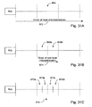
- FIG. 30A shows an example of features located along different scanlines and in different layers
- FIGS. 31A-C show that in one embodiment, a scanline can be focused from the layer closest to the receiver, and that a given layer can be split into finer layers for finer focusing;
- FIGS. 34A-B show some of the many possible ways of combining various signal traces to obtain a best in-focus scanline at a given layer
- FIG. 36B shows a negative image of the photograph of FIG. 36A ;
- FIG. 38 shows an example table of signal values and the corresponding sampled values at example sampling times of the example analog signal of FIG. 37 ;
- FIG. 39 shows an example plot of the sampled values analog signal of FIG. 37 , showing that such sampling can be susceptible to aliasing effects;
- FIG. 40 shows an example relatively fine feature of the analog signal of FIG. 37 being sampled at different phases via various example detectors
- FIG. 42 shows how various parameters related to detection configuration and sampling configuration can determine an effective sampling frequency facilitated by phase-shifted samplings via a plurality of detectors
- FIG. 43 shows a block diagram of one embodiment of an apparatus having a sampling component and a combining component that allows detection and imaging of analog echo signals resulting from relatively fine features in a medium;
- FIGS. 44A-44C show by examples various ways modules or components can be configured in various embodiments of the present teachings
- FIGS. 46 and 47 show examples of how focus of an object in a tissue can be achieved by adjusting various parameters that affect travel times of acoustic energy.
- FIGS. 48 and 48A show schematic diagrams of different example embodiment ultrasound apparatus
- FIG. 49 show a schematic of different steps used to process raw date into an output image
- the imaging device may include both longitudinal-wave and transverse-wave devices.
- the longitudinal-wave device may include, but is not limited to, ultrasound-based devices, sonar-based devices, or devices that probe underground geological features.
- the transverse-wave device may include, but is not limited to, devices that operate based on electromagnetic waves such as optical devices or radar-type devices.
- the example pixel 136 is depicted as being probed by a transmitted signal 138 from an example transmitter 142 .
- the pixel's response to that signal 138 as measured by an example receiver 144 is indicated by a dashed arrow 140 .
- the expectation arrival information for the transmitter-pixel combination depends on the distance d Tx , and can be represented as some form of an index. Such an index can also account for factors other than the distance that affect the arrival of the signal. As an example, electronic circuitry associated with the transmitter may cause the signal to be transmitted after a delay from some start time. Thus, an index data 194 corresponding to the distance d Tx may also include such other factors.
- the expectation arrival information for the receiver-pixel combination depends on the distance d Rx , and can be represented as some form of an index.
- an index can also account for factors other than the distance that affect the arrival of the signal.
- a readout process associated with the receiver may cause the signal to be sampled after a delay from the time when the signal impinges on the receiver.
- an index data 192 corresponding to the distance d may also include such other factors.
- FIG. 6 now shows how an alignment set for the pixel 186 can be used to obtain a selectively sampled signal 210 from an output 206 of the receiver 184 .
- a transmitted signal from the transmitter 182 propagating towards the pixel 186 is depicted as an arrow 202 .
- the signal 202 may or may not experience reflection from the pixel 186 .
- an arrow 204 represents how a reflected signal would propagate from the pixel 186 to the receiver 184 .
- FIGS. 7 and 8 now show processes that perform the index determination and subsequent use, respectively, for an array of transducers.
- a process 220 determines the indices for a given pixel array with respect to a given array of transducers.
- the process 220 begins at a start state 222 , and in a process block 224 , the process 220 obtains detector and map parameters.
- Detector parameters may include the number of transmitters and the number of receivers.
- Map parameters may include the number of pixels, the desired size of the pixels, and the arrangement of the pixels.
- the process 220 in a process block 226 defines the array of transmitters and receivers.
- each transmitter and each receiver are defined in terms of their positions relative to a chosen coordinate system.
- the array definition only needs to be performed for the transducer array. An example array definition is described below in greater detail.
- the process 220 in a process block 228 defines the array of pixels as determined by the map parameters.
- each pixel is defined in terms of its position relative to the transmitter/receiver array. An example array definition is described below in greater detail.
- the process 220 in a process block 230 determines a propagation index corresponding to each transmitter-pixel combination.
- An example propagation index determination is described below in greater detail.
- the process 220 in a process block 232 determines a sampling index corresponding to each receiver-pixel combination.
- An example sampling index determination is described below in greater detail.
- the process 220 in a process block 234 stores the propagation indices and the sampling indices. An example storage of the indices is described below in greater detail.
- the process 220 ends at a stop state 236 .
- the alignment set generation process 220 is performed once for a given transducer array and a given pixel array, and does not need to be re-done during the imaging operation.
- the positions of the transducers 262 are defined with respect to a coordinate system 266 .
- a coordinate system 266 Although a Cartesian coordinate system is used, it will be understood that any coordinate system can be used for such definition.
- the process 270 loops through the receivers. For each receiver, the process 270 loops through the pixels (loop 312 , with end-loop 324 ). Thus for each combination of the receiver and pixel, the process 270 determines the pixel position in a process block 314 .
- the distance between the receiver and the pixel is determined.
- an index corresponding to the propagation time is determined.
- the process 330 obtains a set of indices corresponding to the transmitter-pixel combinations of the operating configuration.
- a set of indices corresponding to the receiver-pixel combinations of the operating configuration is obtained.
- the example process 370 in a process block 372 transmits a signal from a selected transmitter and begins sampling. Such a beginning of sampling can be at a predetermined time relative to the time when the transmitted signal begins propagating from the transmitter.
- the process 370 then loops through all of the pixels in a loop 374 (with an end-loop 390 ). For each pixel, the process 370 sets that pixel's initial value to zero in a process block 376 . Also for that pixel, the process 370 obtains the index i Tx for the current transmitter-pixel combination in a process block 378 .
- the example process 400 in a process block 402 transmits signals from all of the selected transmitters, and begins sampling from one selected receiver. Transmitting of the signals from the selected transmitters can be either simultaneous or in a predetermined sequence. In embodiments where the number of selected transmitters is relatively small, the signals may be transmitted substantially simultaneously, and the sampling may be able to temporally distinguish the transmitter-pixel-receiver combinations. In embodiments where the number of selected transmitters is relatively large, the signals being transmitted simultaneously may not allow effective selective sampling of the transmitter-pixel-receiver combinations.
- the plurality of signals can be transmitted from the transmitters in different ways. Sequenced transmission of signals from the plurality of transmitters can temporally separate the arrivals of the signals at the object 524 , as well as reflected signals at the receiver thereafter. One way to sequence the signal transmission is to begin transmission at the transmitter 16 , followed at a predetermined time by transmission at transmitters 15 and 17 , etc. Such a sequence of transmission can increase the temporal separation of the samplings associated with the array of receivers 522 .
- the common sampling is shown to have a period T sampling that is approximately half of the transmission signal period T signal .
- the sampling frequency in such a situation is approximately twice the transmission signal frequency.
- a sampling frequency should be at least twice the frequency of a signal being analyzed to be able to characterize that signal; and the “twice” lower limit is often referred to as the Nyquist limit.
- sampling the received signals at a effectively higher frequency as described above is one aspect of achieving an improved imaging.
- Such sampling samples both the perturbations of interest and noise.
- another aspect of improved imaging includes a method of combining the samplings from different receivers so that the signal to noise ratio of the sampled perturbations is increased.
- properly correlated analog signals from the selected receivers can be made to interfere with each other.
- the various analog signals can be provided with delays according to the manner in which the signals are correlated.
- the combining of the signals can be performed with any receivers in the array.
- Applicant's experiences have shown that correlating and combining signals from some combinations of transmitter and receivers yield better results in the quality of images.
- FIGS. 18A and 18B show two examples of such transmitter-receiver combinations.
- an example operating configuration 640 has an i-th transmitter 642 a transmitting an energy 646 , and a receiver (i+1) 644 b that is offset by one element spacing receiving a reflected signal 648 (from an arbitrary point 658 in the medium) and generating a signal.
- an energy 650 from a transmitter (i+1) 642 b is reflected as an energy 652 and received by a receiver (i+2) 644 c .
- an energy 654 from a transmitter (i+2) 642 c is reflected as an energy 656 and received by a receiver (i+3) 644 d .
- such transmit-receive combination between transducers offset by one unit provides a substantially “head-on” type of probing of the arbitrary point 658 in the medium.
- an example operating configuration 660 has the i-th transmitter 642 a transmitting an energy 662 , and the receiver (i+3) 644 c that is offset by two element spacing receiving a reflected signal 664 (from the arbitrary point 658 in the medium) and generating a signal.
- an energy 666 from the transmitter (i+1) 642 b is reflected as an energy 668 and received by the receiver (i+3) 644 d .
- Such an offset can provide a more angled probing of the point 658 in the medium.
- offset pairing of the transmitter and receiver can extend to three, four, or greater offset units.
- any offset in the array can be used.
- such a capability can be used to investigate reflections and/or emissions from a given object that are directed towards sidelobe angles.
- FIG. 20 now shows one embodiment of a process 700 that combines the sampled data according to different transmitter-receiver offset groups.
- the process 700 loops through different values of offset N between the transmitter and the receiver of interest (begin loop 702 , end loop 708 ).
- the process 700 forms a “page” of data by combining data from receivers that are offset by the current value of N from the selected transmitters.
- the process stores the page of data corresponding to the current offset value of N.
- FIG. 21 now shows one embodiment of a process 710 that uses the page(s) of data to characterize the medium.
- the process 710 retrieves selected page(s) of data corresponding to transmitter-receiver offset value(s) of N.
- the process 712 combines the selected page(s) to characterize the medium.
- characterization of the medium includes formation of an image of the medium.
- FIGS. 22 to 25 now show a specific example of the data page formation based on the offset of the transmitter and receiver pairs.
- an example operating configuration 730 having six sets of transmitter-receiver assemblies 732 are shown in FIG. 22 . It will be understood that such a configuration is only for descriptive purpose, and is not in any way intended to limit the scope of the present teachings.
- each transmitter-receiver assembly includes a transmitter (Tx) and a receiver (R) positioned in a close proximity to the transmitter. As depicted by an arrow 734 , the six example transmitters (Tx 1 to Tx 6 ) are “fired” in sequence, starting from the first transmitter Tx 1 .
- FIG. 22 Also shown in FIG. 22 is an arbitrary point 736 in the medium.
- a given transmitter does not transmit until return signals from the medium, including the point 736 , would have had time to return to all of the receivers.
- the arbitrary point 736 is shown to aid in the purpose of description, and a-priori knowledge or assumption of it's location with respect to the array 732 is not required.
- FIG. 23B shows example traces 760 associated with transmission from an i-th transmitter Tx(i).
- each of the sampled traces 760 can be sampled between a “Start” time and a “Stop” time while being referenced to a time reference.
- the time reference may or may not be the same as the master time reference described above in reference to FIG. 23A .
- the perturbation signal will likely reach R 2 first, followed by successively later arrivals to other receivers spaced from R 2 .
- the arrival times within the traces 760 can also be compensated for by the method described below.
- FIGS. 24A-F show sampled data traces from the receivers associated with each of the six example transmitters.
- FIGS. 25A-F show the same sampled data traces.
- R 2 is the offset-one receiver.
- R 1 and R 3 are offset-one receivers; thus, data from either or both receivers can be used. Similar offset-one receivers corresponding to other transmitters are shown in FIGS. 24C to 24F .
- FIG. 25G shows a combined data 782 that can result from combination of data 780 a - f for offset-two receivers. If the data are combined properly, the combined data 782 can include an enhanced peak 784 that corresponds to a feature of interest. A method for performing such combination is described below in greater detail.
- FIGS. 26-33 now show how signals from different receivers can be combined so as to yield an enhanced signal of interest.
- the different receivers can be offset receivers, or simply part of multiple receivers.
- FIG. 26 shows that a given receiver 792 can output an example signal 796 having fine perturbations 798 as described above in reference to FIGS. 16 and 17 .
- Such a receiver signal 796 can result from return signals 802 impinging on the receiver 792 from a plurality of directions, including a direction substantially directly in front of it.
- An imaginary line 790 that extends substantially directly front of the receiver is shown in FIG. 26 .
- the line 790 is shown to intersect a layer 794 .
- line 790 and the layer 794 are depicted as being perpendicular, it will be understood that such orientation is not a requirement.
- a line may be oriented at an angle with respect to the layer.
- a layer does not need to have a planar shape—it can be curved and form a portion of a shell-like structure about the receiver.
- receiver signals are combined so as to enhance or “focus” on perturbation features positioned generally along the line 790 and within the layer 794 .
- Such “focused” combination of signals from a plurality of receivers can be thought of as a scanline associated with the receiver 792 .
- a plurality of such scanlines associated with a plurality of receivers can then form an image along the scanlines.
- FIG. 27 shows that a plurality of example scanlines 812 a - c associated with a plurality of receivers 810 a - c can intersect with an example layer 814 . It will be understood that areas defined by such intersections are not necessarily equivalent to a “pixel.” In some applications, the size of a pixel essentially places a limit on the resolution of the image generated therefrom, whether or not the detector is capable of better resolution.
- an example area 818 is defined as an intersection area defined by the scanline 812 b and the layer 814 .
- such an area defines a window (or depth-of-field of the scanline) in which a focus is performed.
- that area can be considered to be a pixel for the purpose of imaging.
- the size of the focus area defined in the foregoing manner does not need to be fixed.
- the layer 814 can be initially selected to be relatively large. Once a “coarse focus” is achieved for such a layer, that layer can be split into thinner layers. Then, the scanline(s) can be “fine focused” if desired and/or able to. Thus, as shown in FIG. 27 , the layer 814 can be split into thinner layers such as an example layer 816 , and a focus area 820 would be associated with that relatively thinner layer.
- FIGS. 28 to 30 now show by example how scanlines associated with three example receivers can be brought into focus at different layers.
- an example array of three receivers 810 a - c are shown in FIGS. 28A , 29 A, and 30 A.
- Associated with the receivers 810 a - c are imaginary lines 812 a - c that extend therefrom respectively.
- the lines 812 a - c are divided into three example layers 822 a - c .
- a first feature of interest 824 is shown to be located generally in an area defined by the line 812 a and the layer 822 b .
- a second feature of interest 826 is shown to be located generally in an area defined by the line 812 b and the layer 822 a .
- a third feature of interest 828 is shown to be located generally in an area defined by the line 812 c and the layer 822 c .
- the three features of interest are depicted as triangle 824 , circle 826 , and square 828 .
- FIGS. 28B , 29 B, and 30 B are also common, showing that data traces 830 a - c associated with their respective receivers 810 a - c “sees” the three example features of interest 824 , 826 , and 828 at relatively different times.
- the triangle 824 is generally in front of and closest to the receiver 810 a . Consequently, as the data trace 830 a associated with the receiver 810 a shows, the receiver 810 a will likely receive a return signal from the triangle 824 first, followed by the receiver 810 b , which in turn is followed by the receiver 810 c .
- the circle 826 is generally in front of and closest to the receiver 810 b . Consequently, as the data trace 830 b shows, the receiver 810 b will likely receive a return signal from the circle 826 first, and the receivers 810 a and 810 c after that.
- the receivers 810 a - c are depicted as being arranged in an ordered array. It will be understood that such a depiction is only for the purpose of describing the concept of relative arrival times of return signals to the different receivers, and how such signals can be combined to form a focused scanline.
- the example receivers 810 a - c are shown in sequence, they do not necessarily need to be as such physically. For example, different receiver-offset data can be combined as described above; and in such situations, the receivers whose signals are being combined may not be next to or even relatively close to each other.
- the arrangement of the receivers 810 a - c should be considered to represent a logical arrangement for the purpose of description.
- FIG. 28C shows an example focused layer 838 a for a scanline 834 associated with the receiver 810 a .
- Depicted along with the scanline 834 are relative peak heights 836 associated with the combined return signals from the three features 824 , 826 , and 828 when the scanline is in focus.
- Relative shifting of return signal traces to achieve the focus is shown as a set 832 of shifted traces. It will be noted that one does not need to know how much to shift one trace relative to another trace beforehand to achieve a focus.
- a method for determining a focused state from different combinations of shifting is described below in greater detail. For the purpose of describing the result of such focusing for a given scanline in reference to FIGS. 28-30 , the scanlines are depicted as being brought into focus.
- the focused layer 838 b results in an enhance peak 842 corresponding to the aligning (by proper shifting of the data traces) of the triangle 824 .
- enhance peak 842 corresponding to the aligning (by proper shifting of the data traces) of the triangle 824 .
- Such enhanced peaks can be utilized to determine whether a scanline is in focus in a given layer. Such determination is described below in greater detail.
- the first and third layers 822 a and 822 c do not have any features.
- an image resulting from a properly focused scanline should not show features in those two layers 822 a and 822 c .
- such a result can be achieved by making a threshold cut on the peak(s) in a given focused layer so that peaks below that threshold are not processed for image formation. For example, if one was to set the threshold so as to accept the enhance peak 842 but reject lower peaks, the first and third focused layers 838 a and 838 c can form focus areas having substantially null images.
- the focused layer 848 a results in an enhanced peak 850 corresponding to the aligning (by proper shifting of the data traces) of the triangle 826 .
- Such an enhanced peak can be used to form an image for the area associated with the line 812 b and the layer 848 a.
- FIG. 30D shows an example focused layer 858 b for the scanline associated with the receiver 810 c . Depicted along with the scanline are relative peak heights associated with the combined return signals from the three features 824 , 826 , and 828 when the scanline is in focus. Relative shifting of return signal traces to achieve the focus is shown as a set 862 of shifted traces.
- FIG. 30E shows an example focused layer 858 c for the scanline associated with the receiver 810 c . Depicted along with the scanline are relative peak heights associated with the combined return signals from the three features 824 , 826 , and 828 when the scanline is in focus. Relative shifting of return signal traces to achieve the focus is shown as a set 864 of shifted traces.
- the foregoing focusing process and/or the focus results therefrom can be implemented with physical movements of one or more transducer elements.
- arrays having movable elements similar to that of adaptive optics can be adjusted to either aid the focusing process, or to re-position the elements so that subsequent focusing process can be achieved more efficiently.
- the corresponding receivers may be moved so as to introduce changes in propagation times thereto, so that likely “focused” sections of the corresponding data traces are now located more centrally, thereby providing more “working” room in the shifting of data traces.
- a “time-shift combination” operation includes shifting of time or phase associated with portions of a plurality of data traces with respect to each other. For example, if a scanline is being focused at a given layer, temporal ranges of data traces being combined can be identified (for example, by an initial estimation based on geometry). Then, digital data within those ranges can be shifted with respect to each other and combined to yield a quality value associated with that combination.
- FIGS. 31A-C show such a successive layer characterization method.
- an arrow 872 directed away from a receiver indicates the order of layer characterization.
- an example layer 866 is shown in FIG. 31A . If that layer is to be split for finer focusing, such as layers 868 a and 868 b in FIG. 31B , characterization of those sub-layers can be characterized successively beginning from the sub-layer closest to the receiver (as indicated by an arrow 874 ). Similarly, each of the sub-layers 868 can be split further into layers 870 a - b and 870 c - d . Again, such layers can be characterized successively beginning from the one closest to the receiver (as indicated by an arrow 876 ).
- FIG. 32 shows a process 880 for determining focused scanlines for one or more receivers at different layers.
- the process 880 further includes finer-focusing capability that splits a given layer if that split provides an improved scanline focus quality.
- the process 880 in general includes a process block 882 where input parameters are obtained. Some of the input parameters are described in a more specific process in reference to FIG. 33 .
- the process 880 in a process block 890 determines a velocity value that results in the best degree of focus for the current scanline in the current layer.
- Various methods of determining the degree of focus selecting the “best” therefrom are described below in greater detail. As previously described, a prior knowledge of velocity value is not necessary. However, providing a likely range of velocity values may result in a more efficient combinatoric computation for combining and determining the degree of focus.
- the process 880 in a process block 890 then updates the velocity data corresponding to the current scanline and the layer.
- Such data can be stored as a table, or any manner that allows retrieval for later use.
- the process 880 in a decision block 904 determines whether the focus has improved by the split. If the answer is “yes,” then the process 880 in a process block 906 updates the velocity table for the sub-layers of the current layers. To see if the focus can be made even finer, thereby improving the resolution, each of the current sub-layers are further split in a process block 908 , and focusing is performed on each of the newly created sub-layers by invoking the sub-layer loop 896 . If the answer in the decision block 904 is “no,” then the process 880 removes the previous split in a process block 910 , since the finer “focus” did not yield a better result.
- FIG. 33 now shows a more specific example process 920 of how the process 880 of FIG. 32 can be implemented.
- the process 920 is described for one given receiver. But as shown in FIG. 32 , such a process can be looped over a plurality of receivers.
- the process 920 in a process block 922 determines the position of a scanline associated with the receiver being analyzed.
- a maximum number of sub-layers within a given layer is obtained. In one embodiment, that maximum number places a limit on the extent of splitting for finer focusing.
- the process 920 obtains a level of focus quality improvement to trigger additional splitting for finer focusing.
- the process 920 obtains a current velocity table for the layers if available and/or desired.
- a seedpoint (such as a value representative of a lowest expected velocity) is obtained if available and/or desired.
- the process 920 obtains the range and increment of velocity for determining the velocity associated with the best degree of focus.
- the splitting of layers can provide a substantial advantage in how effectively a given volume can be imaged.
- a volume includes a relatively small group of features of interest localized in a relatively small region.
- the rest of the volume is substantially homogeneous for the purpose of propagating signals.
- Such homogeneous portions likely will not need to be split, since the velocity therein is substantially uniform.
- the small inhomogeneous region can be split into smaller layers to allow characterization of sub-regions with different velocity values.
- the combining process does not need to waste time attempting to split the homogeneous portion.
- the inhomogeneous region can be characterized better by the splitting method, thereby allowing improved characterization of the volume.
- FIG. 34A shows the shifted data trace set 840 corresponding to “in focus” configuration as described above in reference to FIG. 28D .
- FIG. 34A further shows one of a number of possible ways of determining the degree of focus for the trace combination set 840 .
- a running average of the combined scanline is obtained for a selected window.
- such a window may overlap the focus layer 838 b and extend beyond.
- the window may be defined as temporally substantially similar to the boundaries corresponding to the focus layer 838 b.
- the running averages are formed by a plurality of partially overlapping averaging intervals 970 .
- Average values 972 associated with the intervals 970 are depicted at the approximate centers of the intervals 970 .
- a best degree of focus can be determined by looking for the greatest sum of average values within the window.
- the average values 972 add up to a greater value than that of the average values 982 .
- the data trace combination 840 can be said to be the “in focus” scanline having the best degree of focus value (in this example, the sum of average values).
- quality value can represent the various degrees of focus described herein, and “best quality value” can represent the corresponding “best degree of focus.” It will be understood that the term “best” does not necessarily mean a value having the largest value. It can mean a value having the smallest value, or any value that represents a particular combination having the desired property for the purpose of assigning to a scanline.
- FIGS. 35A and B now show block diagrams of one embodiment of a signal processing assembly 1100 that can perform various functions described herein (such as obtaining data traces from receivers, digitally sampling, and combining the digitally sampled data).
- the assembly 1100 includes a plurality of data channels 1104 that are input into a data combiner 1106 .
- Each data channel 1104 forms a stream of digital data corresponding to data traces from one or more receivers in a manner described below in greater detail.
- digital data represents digital echo signals having amplitudes and time information of samplings of the data traces.
- such digital data from the data channels 1104 are combined by a data combiner 1106 .
- the data combiner 1106 combines the digital data according to the relative orientation of the receivers with respect to transmitters. For example, data corresponding to offset-one receivers can be combined as one set of data.
- such combining of data is performed by parallel processing (as depicted in FIG. 35A ) so as to allow timely processing of a relatively large amount of data.
- each stream of data in the channel 1104 is associated with a receiver and a transmitter.
- focus information can be associated with such receiver and/or transmitter can be provided to the channel 1104 by a focus parameter database 1122 .
- the focus information can include the transmitter and receiver alignment sets can be provided.
- the focus information can include a default velocity information for the receivers.
- an output from the data combiner 1106 represents group(s) of data corresponding to different receiver-transmitter combinations.
- such combined data can form a “page” of data, and such pages of data can be further combined by a page combiner 1108 .
- pixel intensity as determined by selected groups of transmitter-receiver combinations (pages) can be further combined to enhance the real signal from that pixel, by using the transmitter-pixel and pixel-receiver geometries.
- pages of data can be combined with respect to a scanline for a receiver at a given layer, such that each combination yields a degree of focus or a quality value. As described above, a “best” degree of focus or quality value can be determined in a number of ways to select a “best” scanline for the receiver.
- an output from the page combiner 1108 can be stored in a page memory 1110 .
- Such stored page combinations can be refined further as shown. For example, the finer focusing by layer-splitting described above can be facilitated by such a feature.
- the output from the ADC 1140 can be cleaned up and/or formatted for subsequent processing by an optional correlator/filter 1140 .
- the output from the correlator/filter 1140 is input into a data memory 1142 for combining with the focus information from a focus database 1144 as described above in reference to FIG. 35A .
- the output from the data memory 1142 is then sent to the data combiner ( 1106 in FIG. 35A ).
- FIGS. 36A and B now show an example image obtained using some of the imaging methods described herein.
- FIG. 36A shows a black-and-white photograph of the image.
- FIG. 36B shows a negative image of the photograph of FIG. 36A .
- a sectional view of a plurality of wires 1200 is formed by imaging a slice through a medium 1202 where the wires are located.
- Each wire has a diameter (denoted as 1204 ) of approximately 100 micrometers, and a spacing (denoted as 1206 ) between (edge-to-edge) two closest adjacent wires is approximately 100 micrometers.
- the medium 1202 is water contained in a volume of approximately 350 cm 3 , and the wires are located approximately 6.7 cm from an array of receivers (not shown).
- the example 3.5 MHz signal would require sampling at a rate of approximately 7 MHz (twice the signal frequency) or higher for conventional devices.
- the effective size D of the detector can be increased either by increasing the individual detector size, or by forming an array whose overall size can be substantially larger than that of each detector.
- Such methods have been used in some fields.
- Applicant believes that currently, the image quality and resolution as disclosed herein has not been achieved using conventional systems and methods.
- the sampling frequency can be less than the frequencies associated with perturbation features that “ride” on the “carrier-wave” echo of the transmission energy.
- One way to characterize such performance is by way of Nyquist criteria that essentially states that a signal needs to be sampled at a frequency F that is at least twice the frequency of the signal to obtain any useful information. Thus for example, if a signal has a frequency of 1 MHz, it needs to be sampled at 2 MHz or higher.
- aliasing occurs, where frequencies above the Nyquist frequency (F/2) “fold over” to behave like lower frequencies.
- aliased frequency fin the range F/2 to F becomes f that can be expressed as
- the sampling frequency can be less than twice the frequency associated with the size feature of interest.
- the term “frequency” means the frequency associated with the central peak associated with the signal.
- the signal is a sinusoidal wave, its frequency corresponds to the standard meaning. If the signal is a pulse (e.g., Gaussian shaped), then the frequency corresponds to the central peak of the pulse. If the signal is a perturbation feature having a peak structure, then the frequency corresponds to that peak.
- FIGS. 37-42 show an example of an operating principle that could explain why the various techniques of the present disclosure can yield relatively high resolution images (for example, images shown in FIGS. 36A and 36B ).
- FIG. 37 shows an example detectable analog signal 1302 having various fine features. Some of the fine features are noise, and some may be signal(s) of interest that result from interaction of the acoustic energy with one or more objects in the medium. In general, whether a given feature is noise or signal of interest is not known in advance. For the purpose of description, however, a feature 1306 will be assumed to be a signal feature of interest, and the rest of the features on the example signal 1302 will be assumed to be noise. Also, for the purpose of providing a visual reference, an example carrier signal 1304 is superimposed with the signal 1302 . Essentially, the signal 1302 includes the carrier signal combined with the various signal features, including the noise and the example signal feature of interest 1306 .
- the analog signal 1302 is shown to be sampled periodically at example times t 1 to t 8 . Solid dots at the intersections of the analog signal 1302 and the sampling times indicate the signal values at the sampling times.
- the signal values are not obtained. Instead, the analog signal 1302 is digitally sampled at the sampling times.
- a signal having a frequency f o is not reconstructable, without ambiguity, from digitally sampled data if the sampling frequency f s is less than twice the signal frequency f o . If a signal contains various frequency components in a bandwidth B, then that signal is considered to be not reconstructable, without ambiguity, from digitally sampled data is the sampling frequency f s is less than twice the bandwidth B.
- Such a constraint generally imposes a minimum sampling frequency of 2f o (or 2B) commonly referred to as a Nyquist frequency.
- An ambiguity that results from sampling at a frequency below the Nyquist frequency is generally referred to as “aliasing.”
- sampling frequency f s is in the range defined by
- example signal 1302 and the resulting example discrete data set 1320 are associated with a given detector.
- the signal reconstructing capability is essentially constrained by the sampling frequency and other conventional digital signal processing parameters.
- each of the example detectors A to F are shown to be sampled at time t.
- trace A from detector A yields a sampled value of DtA
- trace B from detector B yields a sampled value of DtB, and so on.
- the sampled data DtA unambiguously represents the signal 1332 a at time t.
- the sampled data DtB unambiguously represents the signal 1332 b at time t, and so on.
- the independently obtained data via different detectors unambiguously represent the signal 1332 at different phases of that signal 1332 . If such signals are phase shifted and combined properly, the resulting sampled data representing the different phases can be essentially equivalent to sampling the signal at a higher frequency.
- One or more embodiments of the present disclosure relate to combining a plurality of signal traces from a plurality of detectors so as to allow imaging of relatively fine features in a medium. For example, one embodiment of a method for combining digitally sampled data has been described above in reference to FIGS. 22 to 30 .
- FIG. 42 now shows an overview 1350 of the example process described above in reference to FIGS. 40 and 41 .
- the above-described delays in arrivals of signals 1354 can be facilitated by an orientation of an array of detectors 1352 with respect to a reflecting object 1356 .
- the array 1352 is oriented so a line between the object 1356 and detector A is generally perpendicular to the array 1352 .
- detector A is closest to the object 1356 in the example of FIG. 42 .
- Distances from the object 1356 to detectors B to F are successively greater.
- the differences in pathlengths to the different detectors can depend on factors such as distance 1358 from the array 1352 to the object 1356 and detector spacing 1362 .
- the detector spacing can depend on the detector dimension (for example, when the detectors are closely packed).
- such combination of the digitized data can match data “packets” that correspond a given feature of interest.
- a given data packet for a given signal trace can represent a sampling period.
- combining a plurality of such data packets can yield a combined packet representative of an average sampling period (that is, inverse of the sampling frequency) ⁇ T data .
- the resolution associated with the combined digital data can have a time resolution that depends on the sampling period.
- the number of sampled data that can be combined into a given sampling period can depend on how phase separated the signal traces are at the detectors. As described above in reference to FIG. 42 , phase separations can be affected by factors such as differences in the pathlengths to different detectors.
- the quality and/or efficiency of the combined digital data can be affected by the number of detectors and/or the actual sampling interval. While a larger number of detectors and a smaller actual sampling interval may be desirable, one may need to balance such benefit with detector-imposed geometries and/or computing requirements.
- phase differences introduction of phase differences to a plurality of independent detectors, and independently sampling at those different phases can be generally equivalent to sampling a single signal at an effective sampling interval corresponding to the phase differences.
- the effective sampling interval can be affected (and sometimes selected) by factors such a detector geometry with respect to a given reflecting object, medium, and/or the actual sampling frequency. These factors are introduced by independent sampling by a plurality of detectors, and are generally not constrained by the aliasing effect associated with sampling of a single signal.
- the overall sampling resolution of the combined digital data can be selected based on the effective sampling interval and the number of detectors to combine, both of which can affect how many sampled digital data get combined into a given combined packet.
- the present disclosure allows sampling of analog echo signals having substantial frequency components (for example, noise and/or features of interest) in essentially any range.
- a range includes frequency components from (and including) zero to F/2, where F is the actual sampling frequency for sampling of the analog echo signal; and from (and including) F/2 and higher.
- Such sampling can produce corresponding digital echo signals, and such digital signals can be combined so as to yield an image having a relatively high resolution.
- the foregoing examples of combining sampled analog echo signals can be considered as substantially negating the effects of aliasing within at least the sampled analog echo signals. That is, without such combining of the sampled analog echo signals, reconstruction of analog signals would be subject to aliasing effects, and thus be subject to constraints of certain range(s) of sampling frequency(ies).
- the sampling component or module 1396 can include one or more devices, one or more processes, or any combination thereof, such that the component 1396 facilitates digital sampling of one or more analog echo signals.
- the sampling component 1396 includes an analog-to-digital converter (ADC).
- ADC analog-to-digital converter
- a plurality of ADCs can be associated with respective plurality of analog echo signals from a plurality of receivers.
- the sampling component or module 1396 may provide a functionality of digital sampling of a plurality of analog echo signals.
- the sampling component 1396 includes a processor.
- the sampling component 1396 can include devices or components such as, but not limited to, one or more computers, one or more of various types of filters that facilitate processing of signals, one or more ADCs, and/or one or more devices such as sigma-delta converters.
- the combining component or module 1398 can include one or more devices, one or more processes, or any combination thereof, such that the component 1398 facilitates combining of a plurality of digital echo signals.
- the combining component 1398 includes processor.
- modules or components described herein can be separate units and/or processes, be part of a same unit and/or process, or any combination thereof.
- example modules 1410 are depicted as including separate modules 1412 a - c , where each module can be configured to perform certain function(s) so as to achieve a desired functionality overall.
- an example modules 1422 a - c are depicted as being parts of a unit or process 1420 , such that the unit or process 1420 can be configured to perform different functions via the example modules 1422 a - c so as to achieve a desired functionality overall.
- FIG. 44A example modules 1410 are depicted as including separate modules 1412 a - c , where each module can be configured to perform certain function(s) so as to achieve a desired functionality overall.
- an example modules 1422 a - c are depicted as being parts of a unit or process 1420 , such that the unit or process 1420 can be configured to perform different functions via the example modules 1422 a - c
- an example modules 1432 a and b are depicted as being parts of a unit or process 1430 , such that the unit or process 1430 can be configured to perform different functions via the example modules 1332 a and b .
- the functionality of the unit or process 1430 can be combined with a functionality of a separate example module 1432 c , so as to achieve a desired functionality overall.
- FIGS. 45A and 45B show how such different example configurations can be applied to processors that are configured to facilitate various processes as described herein.
- a processor 1440 can be configured to perform or facilitate performance of one or more processes.
- the example processor 1440 can be incorporated into a single unit.
- a processor 1450 may include a plurality of units 1452 that are configured to provide certain functionalities, such that some combination of such individual functionalities provides one or more functionalities of the processor 1450 .
- the example processor 1450 includes a plurality of separate units.
- FIGS. 45A and 45B can be combined in any manner.
- a processor functionality may be provided by one or more first processors that are similar to that described above in reference to FIG. 45A , and one or more second processors that are similar to that described above in reference to FIG. 45B .
- FIGS. 43-45 show various examples of modules or components that can be configured to perform various techniques of the present disclosure.
- FIG. 46 shows an example imaging situation where an acoustic energy traverses a plurality of layer interfaces between a given transmitter and a voxel and/or between the voxel and a given receiver.
- one of such layers can be a coupling medium between the transmitter/receiver array and the skin of a tissue being imaged.
- the tissue can have one or more layers (between the skin and the voxel) where acoustic energy propagates at different speeds.
- a “layer” is not limited to a planar volume as depicted in FIG. 46 , and can include any volume having an interface.
- FIG. 47 shows an example imaging situation where a tissue volume has a curvature. Human breast is a non-limiting example of such a tissue volume.
- the calculation of propagation time described above may be made by assuming a physical arrangement of tissues and speeds of sound and then calculating wave travel times along the straight line paths between the transducer elements and the voxel of interest.
- refraction may be taken into account. For an assumed physical arrangement of tissues with substantially clear boundaries between substantially homogeneous media with different but constant speeds of sound, it is possible to establish a ray from each transducer element to each voxel, where the ray bends at each interface between two media according to the well known Snell's law as the sound traverses it.
- the sound wave front from any transmitter, or reflected from any scatterer propagates outward as a spheroidal wave front
- the sound traveling on a path between any two points may be thought of as a ray.
- These envisioned sound rays will propagate through each of these layers on their way from each transmitter to the point of interest, and the sound rays will further propagate through the successive layers on their way to any specified receiver.
- the bending of the ray at the interface can be calculated by making the quantity (n)sin(theta) invariant across a boundary where n is refractive index indicative of the speed of sound and theta is the direction of the ray relative to a normal vector through the surface. Once the correct ray and the velocities of the media have been determined the travel time index for that ray may be calculated.
- An assumed geometry need not be limited to homogeneous media but may in fact have speed of sound gradients.
- the bending of the sound rays in a gradient medium can still be estimated by Snell's law.
- FIG. 46 shows an example configuration 2300 having three parallel layers of matter of different assumed sound speeds.
- a transmitter 2303 sends an essentially spherical wave front of sound waves.
- a particular portion of this wave front depicted as a ray 2301 , departs the transmitter 2303 and is bent at interfaces 2305 and 2307 on its way to a pixel 2309 .
- a reflecting or scattering object located at pixel position 2309 may reflect this ray specularly, or it may break it up into another spherical wave front of backscattered sound waves.
- a specific ray 2311 being considered as leaving the pixel 2309 is bent similarly by interfaces 2307 and 2305 on its way to a receiver 2313 .
- variable parameters of, for example, fat thickness may be varied to improve the focus.
- the resulting improved sound speed times for different paths may be stored in, for example, the time index table to be used in assembling the display.
- regions of interest are detected by their boundaries. Examples include fat lobules or cysts within a breast.
- the boundary closest to the transducer may be generally imaged well while the far boundary is generally distorted by the refraction and sound speed change within the region of interest.
- the optimization of the speed of sound may be achieved using many approaches. For example, a fixed set of values may be tried and the value giving the best focus selected. As another example, the value for speed of sound may be adjusted progressively until a peak in quality of focus is passed or until the quality of focus is within an acceptable tolerance.
- ultrasound data may be obtained by transmitting ultrasound from a transmitter and detecting the ultrasound at a plurality of different receivers. This may be repeated for different transmitters.
- the result is a collection of sets of received data.
- Each set of received data corresponds to a particular transmitter-receiver pair.
- Each set of received data may comprise, for example, a sequence of samples of a signal received at a receiver detecting ultrasound
- FIG. 48 shows ultrasound apparatus 3000 comprising a transducer 3001 comprising an array of elements 3002 .
- Each element 3002 can function as a transmitter when driven by transmitter circuitry 3004 or as a receiver when connected to receive circuitry 3006 .
- receive circuitry 3006 comprises a separate receiver 3007 for each element 3002 and each receiver 3007 provides a digital output that is stored in a data structure 3009 in a memory 3010 .
- a switching network 3012 allows any one of elements 3002 to be connected to be driven by transmitter circuitry 3004 while the remaining elements 3002 are connected to the corresponding receiver 3007 .
- Data characterizing a tissue or other medium may be acquired by selecting each element 3002 in turn to be used as a transmitter and, in each turn, receiving digitizing and storing the signals received by each of the other elements.
- FIG. 48A shows ultrasound apparatus 3000 A which is similar to ultrasound apparatus 3000 except that apparatus 3000 A has a transmitter 3004 which includes transmitter circuitry 3004 A dedicated for each transducer element 3002 and apparatus 3000 A does not have a switching network 3012 .
- Apparatus 3000 A may be operated to acquire data by transmitting from one or elements 3002 using the corresponding transmitter circuitry 3004 A, and receiving and storing the resulting signals at elements 3002 as described above for apparatus 3000 .
- Transmission of ultrasound may be performed using a selected subset of the elements. Selected subsets of the elements may be applied to receive signals resulting from transmission from each of the transmit elements. In some embodiments an element may be used as both a transmit element and a receive element in the same turn.
- ultrasound is transmitted into a medium by simultaneously operating two or more transmit elements 3002 .
- a group of elements 3002 may be operated in a coordinated fashion to emit ultrasound having the characteristics of a point source.
- Operating a plurality of transmit elements as a virtual point source is known in the art and described, for example, in Lokke et al. Multielement Synthetic Transmit Aperture Imaging Using Temporal Encoding , IEEE Transactions on Medical Imaging, Vol. 22, No. 4, April 2003, p. 552.
- the location of the virtual point source may be changed by driving the plurality of transmit elements using different driving signals and/or by changing the members of the group of elements used to transmit ultrasound as a virtual point source.
- signals are received by groups of elements 3002 .
- signals from a group of elements may be combined so as to increase an effective sampling rate of ultrasound echo signals.
- FIGS. 48 and 48A show digitized data arranged in a matrix in which columns correspond to the element 3002 used to transmit ultrasound into the medium and rows correspond to the elements at which signals are received.
- column 5 contains a sequence S 35 of digital samples obtained by sampling the 5 th element for signals received in response to ultrasound transmitted using the 3′ element of the transducer.
- the columns may correspond to different locations of the virtual point source instead of different individual transmitting elements.
- Ultrasound data originating from transmitter-receiver pairs that are separated by different distances may contain different information regarding the nature of the medium. For example, different offsets (i.e. different angles subtended by the transmitter and receiver at a point in the medium) interrogate different spatial frequencies in the medium. This effect can be exploited to allow the formation of images with different spatial frequency balances. For example, one image may be formed by selecting image data corresponding to a first offset (or offsets in a first range) while another image is formed by selecting image data corresponding to a second offset (or a second range of offsets). The first image may be enriched in lower spatial frequencies relative to the second image while the second image is enriched in higher spatial frequencies relative to the first image or vice versa, for example.
- Images may be generated from the raw data in memory 3010 .
- Each image may be generated based on less than all of the raw data in memory 3010
- the images may be generated by one or more of:
- a first image that is relatively enriched in low spatial frequencies is generated from ultrasound data selected from transmitter-receiver pairs having a first offset or range of offsets (e.g. transmitter-receiver pairs where the transmitter and receivers are separated by smaller distances).
- a second image that is enriched in higher spatial frequencies relative to the first image is generated from ultrasound data selected from transmitter-receiver pairs having a second offset or range of offsets (e.g. transmitter-receiver pairs where the transmitter and receivers are separated by relatively larger distances).
- the first image may be processed by low-pass spatial filtering. This can help to make continuous anatomical borders appear continuous in the image.
- the resulting low-pass spatial filtered image can then be combined with the second image to yield an image for display.
- the images may optionally be weighted before being combined.
- the second image may comprise a B-mode image.
- the B-mode image may be obtained using methods and apparatus as described herein or using other B-mode imaging methods and apparatus.
- Combining the first and second image may comprise determining a sum or weighted sum of the first and second images for example.
- criteria 3020 A through 3020 E are respectively applied to select subsets 3022 A through 3022 E from raw data 3024 .
- the data subsets are respectively processed by image processing steps 3025 A through 3025 E (collectively image processing steps 3025 ) to yield intermediate images 3027 A through 3027 E.
- Images 3027 A through 3027 E are weighted according to corresponding weights 3028 A through 3028 E (collectively weights 3028 ) before they are combined by image summation stage 3029 to yield a final image 3030 .
- Image processing steps 3025 may, for example, include one or more of:
- apparatus 3000 or 3000 A provides a mechanism for storing user-selected parameters such as weights and/or other image processing parameters such that future images may be processed using the same user-selected parameters.
- Some embodiments provide a data store containing one or more preset sets of parameters. Such embodiments may optionally permit users to alter the parameters either arbitrarily or, in some cases, only within a predetermined limited range of manipulation.
- volumetric images may be derived from data from transmit-receive pairs for which the offsets satisfy different selection criteria. These different volumetric images may be subjected to different image processing steps and then optionally combined to yield a final image.
- the methods described above can be directly extended to the volumetric case.
- Separate images may be formed from data received by elements within each of the other apertures. For example, separate images may be created from the data received at elements within apertures 3045 A and 3045 B.
- images formed from signals received at elements in different apertures tend to have different speckle patterns.
- speckle patterns may be de-emphasized or eliminated by combining images formed from signals received at elements in different apertures. It is most convenient for the receive apertures to be equal in size such that the images to be combined are equivalent. In embodiments where the different apertures have different sizes then the pixel dimensions of the images may be matched by upsampling and/or downsampling before the images are combined. The combining may comprise, for example, summing the images.
- data from all receive elements i.e. N sets of data where N is the number of elements in transducer 3040
- An image processor 3048 is configured to select subsets of the data corresponding to at least first and second apertures and to process each selected subset of the data to yield corresponding images 3049 A, 3049 B and to combine images 3049 A and 3049 B to yield a final image 3049 C.
- Image processing may comprise, for example, performing detection by rectifying and low-pass filtering the image data.
- Log compression and/or other image processing steps may optionally be performed.
- the images may be subsequently combined, for example by addition. With this type of processing, spatial compounding may be achieved with one firing.
- the different processing may comprise one or more of:
- receive apodization may be modified.
- An apodization function weights the contribution of signals to an image such that signals from elements near the center of an aperture are weighted more heavily while signals from elements near edges of the aperture are weighted less heavily.
- the apodization function may comprise a series of values that correspond to positions of the receiving elements in the array.
- an apparatus is configured to analyze image data for borders or edges. This may be achieved through the application of standard image analysis algorithms, for example, or through generating an image in which lower spatial frequency content is emphasized as described above.
- a non-uniform apodization function such as a Hamming or Hanning function
- a uniform apodization function all signals weighted the same
- an apodization function that is closer to a uniform apodization function may provide better results.
- a preliminary image is prepared and image analysis is performed on the preliminary image to identify areas for which different image processing may be desired.
- the image analysis may perform a routine for identifying pixels that are in the vicinity of borders or edges.
- generating the preliminary image is performed using a first number of the stored sampled signals and generating a further image in which apodization functions are selected based on one or more features identified in the preliminary image (e.g. borders or edges) is performed using a second number of the stored sampled signals greater than the first number.
- the identification of borders and edges may be performed with a relatively low expenditure of computational resources.
- Some embodiments implement image processing methods which comprise: generating a first image from raw data as described herein; identifying in the first image first image regions that include borders or edges and second image regions that do not include borders or edges (or have a reduced content of borders and edges); applying a first apodization function to the raw data to obtain pixel values for pixels in the first region; applying a second apodization function to the raw data to obtain pixel values for pixels in the second region; and assembling a second image from the pixel values for the first and second regions.
- the first image is obtained using one of the first and second apodization functions and so the second image may be assembled from pixel values from the first image in one of the first and second regions and pixel values obtained from the raw data using the other one of the first and second apodization functions in the other one of the first and second regions.
- uniform apodization may provide the best results.
- Such areas may be identified by statistical analysis. For example one may compute a ratio of a mean pixel value for the region to a variance of the pixel values in the region. This ratio tends to approach a value of 1.9 in regions approaching pure speckle.
- a first image is obtained by processing raw data as described herein.
- a statistical measure of speckle e.g. mean/variance
- An apodization function is selected for each of the plurality of regions based on the corresponding statistical measure.
- Pixel values are then determined for each of the regions by processing the raw data using the corresponding apodization function.
- a second image is assembled by combining the pixel values for the plurality of regions.
- apodization is optimized individually for a number of different imaging regions.
- Apodization may be optimized on a image pixel by image pixel basis.
- Optimizing receive apodization as described herein may be applied to volumetric imaging as well as to 2D imaging.
Landscapes
- Engineering & Computer Science (AREA)
- Physics & Mathematics (AREA)
- Remote Sensing (AREA)
- Radar, Positioning & Navigation (AREA)
- Health & Medical Sciences (AREA)
- Life Sciences & Earth Sciences (AREA)
- Computer Networks & Wireless Communication (AREA)
- Acoustics & Sound (AREA)
- General Physics & Mathematics (AREA)
- Radiology & Medical Imaging (AREA)
- Veterinary Medicine (AREA)
- Molecular Biology (AREA)
- Surgery (AREA)
- Animal Behavior & Ethology (AREA)
- General Health & Medical Sciences (AREA)
- Public Health (AREA)
- Medical Informatics (AREA)
- Heart & Thoracic Surgery (AREA)
- Biomedical Technology (AREA)
- Pathology (AREA)
- Nuclear Medicine, Radiotherapy & Molecular Imaging (AREA)
- Biophysics (AREA)
- Gynecology & Obstetrics (AREA)
- Ultra Sonic Daignosis Equipment (AREA)
Abstract
Description
where m is a positive integer, fc is the center frequency of the signal, fs is the sampling frequency, and B is the bandwidth of the bandpass signal. In one example where fc=20 MHz, and B=5 MHz, the above aliasing-avoidance condition can be satisfied if fs=22.5, 17.5, or 11.25 MHz for m=1, 2, or 3. These example sampling frequencies are below the commonly-known “Nyquist frequency” of 2fc (=40 MHz in this example); however, they are all above the Nyquist frequency defined in terms of the bandwidth (2B=10 MHz). Additional details about sub-Nyquist sampling and related topics can be found in commonly available textbooks such as “Understanding Digital Signal Processing,” Richard G. Lyons, Prentice Hall PTR Publication.
-
- selecting ultrasound data corresponding to a first offset (or to a first set of selected offsets e.g. offsets in a first range) and performing image processing operations on the selected image data;
- selecting a plurality of sets of ultrasound data corresponding to a plurality of different offsets or sets of selected offsets and preparing an image by performing image processing operations on the different sets of ultrasound data and combining the results of the image processing operations. Different image processing operations may be applied to the different sets of ultrasound data.
-
- a specific offset value;
- an offset value that is a member of a specific set of offset values;
- an offset value above a threshold;
- an offset value below a specified threshold;
- an offset value in a specified range;
- or the like.
-
- low pass filtering;
- high pass filtering;
- bandpass filtering;
- texture analysis;
- edge detection;
- edge enhancement;
- contrast adjustment;
- coloration; and
- pass through (no image processing).
-
- A spatial frequency image having a relatively enhanced low spatial frequency content (e.g. an image acquired from data from transmit-receive pairs separated by smaller distances) may be used for detecting borders and anatomical edges. In the final image, the borders may be superimposed onto a B-mode ultrasound image.
- The energy content of an image may be measured (either for the image as a whole or for one or more selected spatial frequency bands in the image). A measure of energy may be obtained, for example, by summing pixel values (or a function of the pixel values such as the square of the pixel values) over the image If the energy of one intermediate image exceeds a threshold then one or more other intermediate images may be not included in the final images or may be weighted less in the final image.
- If the energy content of an intermediate image having a lower spatial frequency content (or in a lower-spatial frequency band within an intermediate image) exceeds a threshold then a low-pass filter may be applied to the final image so as to emphasize the lower spatial frequency data.
- If the energy content of an intermediate image having a higher spatial frequency content exceeds a threshold then a high-pass filter may be applied to the final image.
Thus, the characteristics of one or more intermediate images may be measured and used in an automated process to determine the selection of which intermediate images are to be included in the final image; determine weights used in combining the intermediate images into the final image and/or control properties of or determine whether or not a filtering operation will be performed on the final image or on one or more of the intermediate images.
-
- selecting different subsets of the raw image data from which to generate images (selecting data corresponding to transmit-receive pairs having different offsets is one example of this);
- changing a parameter used in generating images (one example of this is changing the assumed speed of sound in the medium being investigated);
- changing a parameter which alters the way in which images are generated (for example a parameter that determines the thickness or maximum number of sub-layers in the method illustrated in
FIG. 33 , a parameter that controls the degree of focusing, or the like); - changing the nature of image processing applied to generated images and/or changing parameters that affect the image processing (examples are determining whether or not a particular image will be filtered, what type of filter will be applied to an image, changing parameters that affect the operation of a filter, changing a function used for apodization etc.)
Changes to these parameters may be performed under the control of a user operating a suitable user interface or performed automatically or semi-automatically. For example, in some embodiments a user can identify a parameter to be varied and the system is configured to generate images for a plurality of different values of the parameter. Evaluation of the images may be done by a user or automatically based on suitable criteria.
Claims (24)
Priority Applications (2)
| Application Number | Priority Date | Filing Date | Title |
|---|---|---|---|
| US12/950,341 US8234923B2 (en) | 2004-09-20 | 2010-11-19 | Systems and methods for ultrasound imaging |
| US13/569,081 US9188673B2 (en) | 2004-09-20 | 2012-08-07 | Systems and methods for ultrasound imaging |
Applications Claiming Priority (4)
| Application Number | Priority Date | Filing Date | Title |
|---|---|---|---|
| US10/945,459 US7850611B2 (en) | 2004-09-20 | 2004-09-20 | System and methods for improved ultrasound imaging |
| US11/314,139 US7819805B2 (en) | 2004-09-20 | 2005-12-21 | Sub-nyquist sampling of acoustic signals in ultrasound imaging |
| US11/385,482 US7862508B2 (en) | 2004-09-20 | 2006-03-20 | Systems and methods for ultrasound imaging |
| US12/950,341 US8234923B2 (en) | 2004-09-20 | 2010-11-19 | Systems and methods for ultrasound imaging |
Related Parent Applications (1)
| Application Number | Title | Priority Date | Filing Date |
|---|---|---|---|
| US11/385,482 Continuation-In-Part US7862508B2 (en) | 2004-09-20 | 2006-03-20 | Systems and methods for ultrasound imaging |
Related Child Applications (1)
| Application Number | Title | Priority Date | Filing Date |
|---|---|---|---|
| US13/569,081 Continuation US9188673B2 (en) | 2004-09-20 | 2012-08-07 | Systems and methods for ultrasound imaging |
Publications (2)
| Publication Number | Publication Date |
|---|---|
| US20110125017A1 US20110125017A1 (en) | 2011-05-26 |
| US8234923B2 true US8234923B2 (en) | 2012-08-07 |
Family
ID=44062580
Family Applications (2)
| Application Number | Title | Priority Date | Filing Date |
|---|---|---|---|
| US12/950,341 Expired - Lifetime US8234923B2 (en) | 2004-09-20 | 2010-11-19 | Systems and methods for ultrasound imaging |
| US13/569,081 Expired - Lifetime US9188673B2 (en) | 2004-09-20 | 2012-08-07 | Systems and methods for ultrasound imaging |
Family Applications After (1)
| Application Number | Title | Priority Date | Filing Date |
|---|---|---|---|
| US13/569,081 Expired - Lifetime US9188673B2 (en) | 2004-09-20 | 2012-08-07 | Systems and methods for ultrasound imaging |
Country Status (1)
| Country | Link |
|---|---|
| US (2) | US8234923B2 (en) |
Cited By (11)
| Publication number | Priority date | Publication date | Assignee | Title |
|---|---|---|---|---|
| US20130111995A1 (en) * | 2010-07-16 | 2013-05-09 | Bernd Koehler | Destruction-free and contactless inspection method and inspection apparatus for surfaces of components with ultrasound waves |
| US20130178740A1 (en) * | 2012-01-05 | 2013-07-11 | Samsung Medison Co., Ltd. | Method and apparatus for providing ultrasound image |
| US20130294665A1 (en) * | 2012-05-01 | 2013-11-07 | Siemens Medical Solutions Usa, Inc. | Component Frame Enhancement for Spatial Compounding in Ultrasound Imaging |
| US9188673B2 (en) | 2004-09-20 | 2015-11-17 | Innervision Medical Technologies Inc. | Systems and methods for ultrasound imaging |
| US9658331B2 (en) | 2012-11-23 | 2017-05-23 | Carestream Health, Inc. | Synthetic aperture doppler ultrasound methods and apparatus |
| US20180074025A1 (en) * | 2016-09-15 | 2018-03-15 | Texas Instruments Incorporated | Ultrasonic Vibration Sensing |
| US10891462B2 (en) | 2018-06-29 | 2021-01-12 | Saudi Arabian Oil Company | Identifying geometrical properties of rock structure through digital imaging |
| US10983237B2 (en) | 2018-04-13 | 2021-04-20 | Saudi Arabian Oil Company | Enhancing seismic images |
| US10991078B2 (en) | 2017-09-15 | 2021-04-27 | Saudi Arabian Oil Company | Inferring petrophysical properties of hydrocarbon reservoirs using a neural network |
| US11668847B2 (en) | 2021-01-04 | 2023-06-06 | Saudi Arabian Oil Company | Generating synthetic geological formation images based on rock fragment images |
| US12123299B2 (en) | 2021-08-31 | 2024-10-22 | Saudi Arabian Oil Company | Quantitative hydraulic fracturing surveillance from fiber optic sensing using machine learning |
Families Citing this family (46)
| Publication number | Priority date | Publication date | Assignee | Title |
|---|---|---|---|---|
| EP2088932B1 (en) | 2006-10-25 | 2020-04-08 | Maui Imaging, Inc. | Method and apparatus to produce ultrasonic images using multiple apertures |
| US9788813B2 (en) | 2010-10-13 | 2017-10-17 | Maui Imaging, Inc. | Multiple aperture probe internal apparatus and cable assemblies |
| US9339256B2 (en) | 2007-10-01 | 2016-05-17 | Maui Imaging, Inc. | Determining material stiffness using multiple aperture ultrasound |
| US9247926B2 (en) | 2010-04-14 | 2016-02-02 | Maui Imaging, Inc. | Concave ultrasound transducers and 3D arrays |
| US9282945B2 (en) | 2009-04-14 | 2016-03-15 | Maui Imaging, Inc. | Calibration of ultrasound probes |
| CN101441401B (en) * | 2007-11-20 | 2012-07-04 | 深圳迈瑞生物医疗电子股份有限公司 | Method and device for rapidly determining imaging area in imaging system |
| KR101659910B1 (en) | 2008-08-08 | 2016-09-27 | 마우이 이미징, 인코포레이티드 | Imaging with multiple aperture medical ultrasound and synchronization of add-on systems |
| JP5485373B2 (en) | 2009-04-14 | 2014-05-07 | マウイ イマギング,インコーポレーテッド | Multiple aperture ultrasonic array alignment system |
| JP2011005042A (en) * | 2009-06-26 | 2011-01-13 | Canon Inc | Photoacoustic imaging apparatus and photoacoustic imaging method |
| WO2011024074A2 (en) | 2009-08-26 | 2011-03-03 | Insightec Ltd. | Asymmetric phased-array ultrasound transducer |
| EP2489034B1 (en) * | 2009-10-14 | 2016-11-30 | Insightec Ltd. | Mapping ultrasound transducers |
| KR102322776B1 (en) | 2010-02-18 | 2021-11-04 | 마우이 이미징, 인코포레이티드 | Method of constructing an ultrasound image and multi-aperture ultrasound imaging system therefor |
| US9852727B2 (en) | 2010-04-28 | 2017-12-26 | Insightec, Ltd. | Multi-segment ultrasound transducers |
| WO2011148275A1 (en) * | 2010-05-26 | 2011-12-01 | Koninklijke Philips Electronics N.V. | High volume rate 3d ultrasonic diagnostic imaging of the heart |
| US10096073B2 (en) | 2011-05-13 | 2018-10-09 | The Climate Corporation | Systems to prescribe and deliver fertilizer over agricultural fields and related methods |
| US10842144B2 (en) * | 2011-05-13 | 2020-11-24 | The Climate Corporation | Method and system to map biological pests in agricultural fields using remotely-sensed data for field scouting and targeted chemical application |
| KR101940481B1 (en) * | 2011-05-18 | 2019-04-10 | 엘지이노텍 주식회사 | Camera module and method for driving the same |
| NL2007348C2 (en) * | 2011-09-05 | 2012-07-02 | Ntgen Tech Dienst B V R | Method and system for examining the interior material of an object, such as a pipeline or a human body, from a surface of the object using ultrasound. |
| JP6407719B2 (en) | 2011-12-01 | 2018-10-17 | マウイ イマギング,インコーポレーテッド | Motion detection using ping base and multi-aperture Doppler ultrasound |
| JP2015503404A (en) | 2011-12-29 | 2015-02-02 | マウイ イマギング,インコーポレーテッド | Arbitrary path M-mode ultrasound imaging |
| JP5984243B2 (en) * | 2012-01-16 | 2016-09-06 | 東芝メディカルシステムズ株式会社 | Ultrasonic diagnostic apparatus, medical image processing apparatus, and program |
| EP2833791B1 (en) | 2012-03-26 | 2022-12-21 | Maui Imaging, Inc. | Methods for improving ultrasound image quality by applying weighting factors |
| JP5840070B2 (en) * | 2012-05-08 | 2016-01-06 | 富士フイルム株式会社 | Photoacoustic measuring device and probe for photoacoustic measuring device |
| JP5851345B2 (en) * | 2012-05-25 | 2016-02-03 | 富士フイルム株式会社 | Ultrasonic diagnostic apparatus and data processing method |
| JP6071260B2 (en) * | 2012-06-13 | 2017-02-01 | キヤノン株式会社 | Subject information acquisition apparatus and information processing method |
| CN104620128B (en) | 2012-08-10 | 2017-06-23 | 毛伊图像公司 | Calibration of Multi-aperture Ultrasonic Probes |
| CN103676827A (en) | 2012-09-06 | 2014-03-26 | Ip音乐集团有限公司 | System and method for remotely controlling audio equipment |
| US9986969B2 (en) | 2012-09-06 | 2018-06-05 | Maui Imaging, Inc. | Ultrasound imaging system memory architecture |
| WO2014160291A1 (en) | 2013-03-13 | 2014-10-02 | Maui Imaging, Inc. | Alignment of ultrasound transducer arrays and multiple aperture probe assembly |
| DE102013106359A1 (en) * | 2013-06-18 | 2014-12-18 | Atlas Elektronik Gmbh | Method for determining an optimal subsonic sound velocity and apparatus for carrying out the method |
| CN104323794B (en) * | 2013-07-22 | 2016-12-28 | 华中科技大学 | A kind of split-type ranks addressing method for 3-D supersonic imaging |
| US9883848B2 (en) | 2013-09-13 | 2018-02-06 | Maui Imaging, Inc. | Ultrasound imaging using apparent point-source transmit transducer |
| KR102087986B1 (en) * | 2013-10-04 | 2020-03-11 | 삼성전자주식회사 | Method and apparatus for processing image data and medium record of |
| US10746859B2 (en) * | 2014-03-31 | 2020-08-18 | Koninklijke Philips N.V. | System and method for acoustic imaging with coherent compounding using intercostal spaces |
| US10401493B2 (en) | 2014-08-18 | 2019-09-03 | Maui Imaging, Inc. | Network-based ultrasound imaging system |
| EP3203917A4 (en) * | 2014-10-07 | 2018-09-26 | Butterfly Network, Inc. | Ultrasound signal processing circuitry and related apparatus and methods |
| WO2016152602A1 (en) * | 2015-03-23 | 2016-09-29 | 富士フイルム株式会社 | Acoustic wave image generating device and control method therefor |
| CN107613878B (en) | 2015-03-30 | 2021-04-06 | 毛伊图像公司 | Ultrasound imaging system and method for detecting object motion |
| EP4697068A3 (en) | 2016-01-27 | 2026-04-22 | Maui Imaging, Inc. | Ultrasound imaging with sparse array probes |
| GB2566437B (en) | 2017-07-26 | 2022-12-07 | Sezanne Marine Ltd | Systems and methods for acoustic and/or electromagnetic imaging |
| US10868547B2 (en) * | 2018-09-25 | 2020-12-15 | Stmicroelectronics (Grenoble 2) Sas | Device for determining a propagation time |
| EP3632330B1 (en) * | 2018-10-04 | 2022-08-24 | SuperSonic Imagine | Method for determining a speed of sound in a medium, an ultrasound imaging system implementing said method |
| JP7724853B2 (en) | 2020-10-21 | 2025-08-18 | マウイ イマギング,インコーポレーテッド | Systems and methods for tissue characterization using multiple aperture ultrasound |
| EP4236811A4 (en) | 2020-11-02 | 2024-10-09 | Maui Imaging, Inc. | SYSTEMS AND METHODS FOR ENHANCING ULTRASOUND IMAGE QUALITY |
| CN117860202B (en) * | 2024-02-01 | 2025-10-28 | 中国科学技术大学 | A high-frequency photoacoustic computed tomography method based on sub-Nyquist sampling |
| CN119420465B (en) * | 2024-11-01 | 2025-09-16 | 北京邮电大学 | Side channel attack method, device and medium |
Citations (91)
| Publication number | Priority date | Publication date | Assignee | Title |
|---|---|---|---|---|
| US3895381A (en) | 1973-02-21 | 1975-07-15 | Winston E Kock | Synthetic aperture imaging systems |
| US4072922A (en) | 1975-11-13 | 1978-02-07 | Seiscom Delta Inc. | Method for seismic exploration for enhanced results in simulated cylindrical or plane waves |
| US4105018A (en) | 1976-02-02 | 1978-08-08 | University Of Utah | Acoustic examination, material characterization and imaging of the internal structure of a body by measurement of the time-of-flight of acoustic energy therethrough |
| US4259733A (en) | 1979-05-14 | 1981-03-31 | Seiscom Delta, Inc. | Multi-dimensional seismic imaging |
| US4325257A (en) | 1980-02-20 | 1982-04-20 | Kino Gordon S | Real-time digital, synthetic-focus, acoustic imaging system |
| US4452084A (en) | 1982-10-25 | 1984-06-05 | Sri International | Inherent delay line ultrasonic transducer and systems |
| US4539847A (en) | 1984-01-03 | 1985-09-10 | Texaco Inc. | Acoustic method and apparatus for measuring thickness of a coating layer on a substrate |
| US4566459A (en) | 1983-02-14 | 1986-01-28 | Hitachi, Ltd. | Ultrasonic diagnosis system |
| US4567768A (en) * | 1984-01-18 | 1986-02-04 | Kabushiki Kaisha Toshiba | Ultrasonic image output apparatus |
| US4662222A (en) | 1984-12-21 | 1987-05-05 | Johnson Steven A | Apparatus and method for acoustic imaging using inverse scattering techniques |
| US4669482A (en) | 1985-10-28 | 1987-06-02 | Board Of Regents, The University Of Texas System | Pulse echo method and apparatus for sound velocity estimation in vivo |
| US4781199A (en) | 1985-01-07 | 1988-11-01 | Kabushiki Kaisha Toshiba | System and method for measuring sound velocity of internal tissue in an object being investigated |
| US4817434A (en) | 1985-11-19 | 1989-04-04 | Forrest Anderson | Device for imaging three dimensions using simultaneous multiple beam formation |
| US5141738A (en) | 1983-04-15 | 1992-08-25 | Schering Aktiengesellschaft | Ultrasonic contrast medium comprising gas bubbles and solid lipophilic surfactant-containing microparticles and use thereof |
| US5161536A (en) | 1991-03-22 | 1992-11-10 | Catheter Technology | Ultrasonic position indicating apparatus and methods |
| US5197475A (en) | 1988-08-10 | 1993-03-30 | The Board Of Regents, The University Of Texas System | Method and apparatus for analyzing material properties using ultrasound |
| WO1993012444A2 (en) | 1991-12-11 | 1993-06-24 | Synthetic Aperture Real Time Imaging Corporation | Synthetic aperture ultrasound imaging system |
| US5226019A (en) | 1992-01-10 | 1993-07-06 | Amoco Corporation | Method of geophysical exploration |
| US5293871A (en) | 1993-05-05 | 1994-03-15 | Cornell Research Foundation Inc. | System for ultrasonically determining corneal layer thicknesses and shape |
| US5299576A (en) | 1991-11-29 | 1994-04-05 | Fujitsu Limited | Ultrasonic synthetic aperture diagnostic apparatus |
| US5345426A (en) | 1993-05-12 | 1994-09-06 | Hewlett-Packard Company | Delay interpolator for digital phased array ultrasound beamformers |
| US5526815A (en) | 1993-01-29 | 1996-06-18 | Siemens Aktiengesellschat | Therapy apparatus for locating and treating a zone located in the body of a life form with acoustic waves |
| US5544659A (en) | 1994-12-29 | 1996-08-13 | Siemens Medical Systems, Inc. | Ultrasonic doppler imager having a reduced hardware adaptive tissue rejection filter arrangement |
| US5558092A (en) | 1995-06-06 | 1996-09-24 | Imarx Pharmaceutical Corp. | Methods and apparatus for performing diagnostic and therapeutic ultrasound simultaneously |
| US5568812A (en) * | 1994-01-25 | 1996-10-29 | Aloka Co., Ltd. | Diagnostic ultrasound apparatus |
| US5570691A (en) | 1994-08-05 | 1996-11-05 | Acuson Corporation | Method and apparatus for real-time, concurrent adaptive focusing in an ultrasound beamformer imaging system |
| US5628320A (en) | 1996-03-29 | 1997-05-13 | Siemens Medical Systems, Inc. | Ultrasound image reconstruction using back-propagation |
| JPH09201361A (en) | 1995-11-21 | 1997-08-05 | Toshiba Corp | Ultrasound diagnostic equipment |
| US5673697A (en) | 1996-04-24 | 1997-10-07 | Raytheon Company | High-resolution three, dimensional ultrasound imaging device |
| EP0812005A2 (en) | 1996-06-06 | 1997-12-10 | University Of Bristol | Post-reception focusing in remote detection systems |
| US5720291A (en) | 1996-03-22 | 1998-02-24 | Advanced Technology Laboratories, Inc. | Three dimensional medical ultrasonic diagnostic image of tissue texture and vasculature |
| US5784334A (en) | 1996-03-13 | 1998-07-21 | Atlantic Richfield Company | Method and system for detecting hydrocarbon reservoirs using amplitude versus offset analysis of seismic signals |
| US5838564A (en) | 1994-12-12 | 1998-11-17 | Amoco Corporation | Apparatus for seismic signal processing and exploration |
| US5850622A (en) | 1996-11-08 | 1998-12-15 | Amoco Corporation | Time-frequency processing and analysis of seismic data using very short-time fourier transforms |
| US5862100A (en) | 1996-05-28 | 1999-01-19 | Atlantic Richfield Company | Method and system for detecting hydrocarbon reservoirs using statistical normalization of amplitude-versus-offset indicators based upon seismic signals |
| US5870691A (en) | 1996-12-06 | 1999-02-09 | Amoco Corporation | Spectral decomposition for seismic interpretation |
| JPH1189833A (en) | 1997-09-16 | 1999-04-06 | Aloka Co Ltd | Ultrasonic bone measuring instrument |
| US5892732A (en) | 1996-04-12 | 1999-04-06 | Amoco Corporation | Method and apparatus for seismic signal processing and exploration |
| US5930730A (en) | 1994-12-12 | 1999-07-27 | Amoco Corporation | Method and apparatus for seismic signal processing and exploration |
| US5940778A (en) | 1997-07-31 | 1999-08-17 | Bp Amoco Corporation | Method of seismic attribute generation and seismic exploration |
| US5969661A (en) | 1996-06-06 | 1999-10-19 | University Of Bristol | Apparatus for and method of detecting a reflector within a medium |
| US5999836A (en) | 1995-06-06 | 1999-12-07 | Nelson; Robert S. | Enhanced high resolution breast imaging device and method utilizing non-ionizing radiation of narrow spectral bandwidth |
| US6007499A (en) | 1997-10-31 | 1999-12-28 | University Of Washington | Method and apparatus for medical procedures using high-intensity focused ultrasound |
| US6049509A (en) | 1995-04-27 | 2000-04-11 | Geco A.S. | Method of processing seismic data to obtain the travel time curve |
| US6050943A (en) | 1997-10-14 | 2000-04-18 | Guided Therapy Systems, Inc. | Imaging, therapy, and temperature monitoring ultrasonic system |
| US6058074A (en) | 1998-07-31 | 2000-05-02 | Atlantic Richfield Company | Method and system for detecting hydrocarbon reservoirs using amplitude-versus-offset analysis with improved measurement of background statistics |
| US6092026A (en) | 1998-01-22 | 2000-07-18 | Bp Amoco Corporation | Seismic signal processing and exploration |
| WO2000043809A1 (en) | 1999-01-21 | 2000-07-27 | David Smythe | 3d/4d ultrasound imaging system |
| US6135960A (en) | 1998-08-31 | 2000-10-24 | Holmberg; Linda Jean | High-resolution, three-dimensional whole body ultrasound imaging system |
| US6138075A (en) | 1998-08-05 | 2000-10-24 | Landmark Graphics Corporation | Methods and apparatus for analyzing seismic data |
| US6166384A (en) | 1998-11-06 | 2000-12-26 | General Electric Company | Method and apparatus for minimizing blurring and generating a high resolution image in a radiation imaging system |
| US6210335B1 (en) * | 1999-12-08 | 2001-04-03 | General Electric Company | Acoustic flash to increase penetration |
| US6213958B1 (en) | 1996-08-29 | 2001-04-10 | Alan A. Winder | Method and apparatus for the acoustic emission monitoring detection, localization, and classification of metabolic bone disease |
| US6231511B1 (en) | 1997-11-10 | 2001-05-15 | Medison Co., Ltd. | Ultrasonic signal focusing method and apparatus for ultrasonic imaging system |
| US6238342B1 (en) | 1998-05-26 | 2001-05-29 | Riverside Research Institute | Ultrasonic tissue-type classification and imaging methods and apparatus |
| US6264609B1 (en) | 1999-09-15 | 2001-07-24 | Wake Forest University | Ultrasound apparatus and method for tissue characterization |
| US6278949B1 (en) | 1998-11-25 | 2001-08-21 | M. Aftab Alam | Method for multi-attribute identification of structure and stratigraphy in a volume of seismic data |
| US6289230B1 (en) | 1998-07-07 | 2001-09-11 | Lightouch Medical, Inc. | Tissue modulation process for quantitative noninvasive in vivo spectroscopic analysis of tissues |
| US6363033B1 (en) | 1994-08-05 | 2002-03-26 | Acuson Corporation | Method and apparatus for transmit beamformer system |
| US6374185B1 (en) | 2000-02-18 | 2002-04-16 | Rdsp I, L.P. | Method for generating an estimate of lithological characteristics of a region of the earth's subsurface |
| US20020065466A1 (en) | 1998-03-20 | 2002-05-30 | Barbara Ann Karmanos Cancer Institute | Method and apparatus for high-resolution detection and characterization of medical pathologies |
| US6436046B1 (en) | 1997-12-18 | 2002-08-20 | Acuson Corporation | Diagnostic ultrasound imaging method and system with improved frame rate |
| WO2002084594A2 (en) | 2001-04-18 | 2002-10-24 | Voxar Limited | Correction of boundary artefacts in image data processing |
| US6475150B2 (en) | 2000-12-01 | 2002-11-05 | The Regents Of The University Of California | System and method for ultrasonic tomography |
| US6480790B1 (en) | 1999-10-29 | 2002-11-12 | Exxonmobil Upstream Research Company | Process for constructing three-dimensional geologic models having adjustable geologic interfaces |
| US6487502B1 (en) | 2000-12-01 | 2002-11-26 | Rdsp I, L.P. | System for estimating the locations of shaley subsurface formations |
| US6499536B1 (en) | 1997-12-22 | 2002-12-31 | Eureka Oil Asa | Method to increase the oil production from an oil reservoir |
| US6508768B1 (en) | 2000-11-22 | 2003-01-21 | University Of Kansas Medical Center | Ultrasonic elasticity imaging |
| US6526163B1 (en) | 1998-11-23 | 2003-02-25 | G.E. Diasonics Ltd. | Ultrasound system with parallel processing architecture |
| US6547732B2 (en) | 1998-10-01 | 2003-04-15 | Koninklijke Philips Electronics N.V. | Adaptive image processing for spatial compounding |
| US6585647B1 (en) | 1998-07-21 | 2003-07-01 | Alan A. Winder | Method and means for synthetic structural imaging and volume estimation of biological tissue organs |
| US6668654B2 (en) | 2001-08-15 | 2003-12-30 | Lockheed Martin Corporation | Method and apparatus for generating specific frequency response for ultrasound testing |
| US6672165B2 (en) | 2000-08-29 | 2004-01-06 | Barbara Ann Karmanos Cancer Center | Real-time three dimensional acoustoelectronic imaging and characterization of objects |
| US6681185B1 (en) | 2002-07-26 | 2004-01-20 | Eseis | Method of seismic signal processing |
| US6692450B1 (en) | 2000-01-19 | 2004-02-17 | Medtronic Xomed, Inc. | Focused ultrasound ablation devices having selectively actuatable ultrasound emitting elements and methods of using the same |
| US20040054283A1 (en) | 2002-08-28 | 2004-03-18 | Scott Corey | Apparatus for hematocrit determination and method for its use |
| US6719693B2 (en) | 2002-03-29 | 2004-04-13 | Becs Technology, Inc. | Apparatus and system for real-time synthetic focus ultrasonic imaging |
| US6755787B2 (en) | 1998-06-02 | 2004-06-29 | Acuson Corporation | Medical diagnostic ultrasound system and method for versatile processing |
| JP2004215987A (en) | 2003-01-16 | 2004-08-05 | Matsushita Electric Ind Co Ltd | Ultrasonic diagnostic apparatus and ultrasonic diagnostic method |
| FR2851662A1 (en) | 2003-02-24 | 2004-08-27 | Socomate Internat | Medium e.g. linear probe, discontinuity detecting method for e.g. portable medical apparatus, involves applying coherence criteria to selected maxima for regrouping maxima to same discontinuity, where maxima has value higher than threshold |
| US20040236217A1 (en) | 2003-05-22 | 2004-11-25 | Cerwin Stephen Anthony | Electromagnetic-acoustic Imaging |
| JP2004337457A (en) | 2003-05-16 | 2004-12-02 | Olympus Corp | Ultrasonic image processor |
| US6847737B1 (en) | 1998-03-13 | 2005-01-25 | University Of Houston System | Methods for performing DAF data filtering and padding |
| WO2005009245A1 (en) | 2003-07-15 | 2005-02-03 | Board Of Regents The University Of Texas System | Rapid and accurate detection of bone quality using ultrasound critical angle reflectometry |
| US20050131300A1 (en) | 2003-12-15 | 2005-06-16 | Siemens Medical Solutions Usa, Inc. | Automatic optimization for ultrasound medical imaging |
| JP2005526539A (en) | 2002-01-07 | 2005-09-08 | ジーイー・メディカル・システムズ・イスラエル・リミテッド | System and method for mapping irregularities in hard tissue |
| US20050215883A1 (en) | 2004-02-06 | 2005-09-29 | Hundley William G | Non-invasive imaging for determination of global tissue characteristics |
| US7104956B1 (en) | 1996-11-08 | 2006-09-12 | Research Corporation Technologies, Inc. | Finite amplitude distortion-based inhomogeneous pulse echo ultrasonic imaging |
| US7283652B2 (en) | 2002-11-27 | 2007-10-16 | General Electric Company | Method and system for measuring disease relevant tissue changes |
| US7682311B2 (en) * | 2005-09-22 | 2010-03-23 | Siemens Medical Solutions Usa, Inc. | Phase unwrapped velocity display for ultrasound medical imaging |
| US7822250B2 (en) * | 2005-08-29 | 2010-10-26 | Shenzhen Mindray Bio-Medical Electronics Co., Ltd. | Method and apparatus for ultrasonic imaging in mmode |
Family Cites Families (22)
| Publication number | Priority date | Publication date | Assignee | Title |
|---|---|---|---|---|
| JPS605136A (en) * | 1983-06-24 | 1985-01-11 | 株式会社日立製作所 | Ultrasonic tomography device |
| US5111823A (en) * | 1989-04-20 | 1992-05-12 | National Fertility Institute | Apparatus and method for generating echographic images |
| US5278757A (en) | 1991-11-15 | 1994-01-11 | The Trustees Of The University Of Pennsylvania | Synthetic aperture ultrasonic imaging system using a minimum or reduced redundancy phased array |
| US5581517A (en) | 1994-08-05 | 1996-12-03 | Acuson Corporation | Method and apparatus for focus control of transmit and receive beamformer systems |
| US6174286B1 (en) | 1998-11-25 | 2001-01-16 | Acuson Corporation | Medical diagnostic ultrasound method and system for element switching |
| US6251073B1 (en) | 1999-08-20 | 2001-06-26 | Novasonics, Inc. | Miniaturized ultrasound apparatus and method |
| US6309356B1 (en) | 2000-03-06 | 2001-10-30 | Acuson Corporation | Method and apparatus for forming medical ultrasound images |
| US6551246B1 (en) | 2000-03-06 | 2003-04-22 | Acuson Corporation | Method and apparatus for forming medical ultrasound images |
| US6416477B1 (en) * | 2000-08-22 | 2002-07-09 | Koninklijke Philips Electronics N.V. | Ultrasonic diagnostic systems with spatial compounded panoramic imaging |
| US6464638B1 (en) * | 2000-10-05 | 2002-10-15 | Koninklijke Philips Electronics N.V. | Ultrasound imaging system and method for spatial compounding |
| US7011632B2 (en) * | 2001-09-18 | 2006-03-14 | Kretztechnik Ag | Methods and apparatus for ultrasonic compound imaging |
| US7285094B2 (en) | 2002-01-30 | 2007-10-23 | Nohara Timothy J | 3D ultrasonic imaging apparatus and method |
| US6679847B1 (en) | 2002-04-30 | 2004-01-20 | Koninklijke Philips Electronics N.V. | Synthetically focused ultrasonic diagnostic imaging system for tissue and flow imaging |
| US6866632B1 (en) | 2002-09-18 | 2005-03-15 | Zonare Medical Systems, Inc. | Adaptive receive aperture for ultrasound image reconstruction |
| US7914454B2 (en) | 2004-06-25 | 2011-03-29 | Wilk Ultrasound Of Canada, Inc. | Real-time 3D ultrasonic imaging apparatus and method |
| US8234923B2 (en) | 2004-09-20 | 2012-08-07 | Innervision Medical Technologies Inc. | Systems and methods for ultrasound imaging |
| US7963919B2 (en) | 2005-12-07 | 2011-06-21 | Siemens Medical Solutions Usa, Inc. | Ultrasound imaging transducer array for synthetic aperture |
| US20080114251A1 (en) | 2006-11-10 | 2008-05-15 | Penrith Corporation | Transducer array imaging system |
| US8430819B2 (en) * | 2010-05-28 | 2013-04-30 | General Electric Company | System and method for ultrasound imaging with a configurable receive aperture |
| EP2574956A1 (en) * | 2011-09-30 | 2013-04-03 | GE Inspection Technologies Ltd | Ultrasound imaging system and method with side lobe suppression via coherency factor weighting |
| JP2015503404A (en) * | 2011-12-29 | 2015-02-02 | マウイ イマギング,インコーポレーテッド | Arbitrary path M-mode ultrasound imaging |
| US9986969B2 (en) * | 2012-09-06 | 2018-06-05 | Maui Imaging, Inc. | Ultrasound imaging system memory architecture |
-
2010
- 2010-11-19 US US12/950,341 patent/US8234923B2/en not_active Expired - Lifetime
-
2012
- 2012-08-07 US US13/569,081 patent/US9188673B2/en not_active Expired - Lifetime
Patent Citations (97)
| Publication number | Priority date | Publication date | Assignee | Title |
|---|---|---|---|---|
| US3895381A (en) | 1973-02-21 | 1975-07-15 | Winston E Kock | Synthetic aperture imaging systems |
| US4072922A (en) | 1975-11-13 | 1978-02-07 | Seiscom Delta Inc. | Method for seismic exploration for enhanced results in simulated cylindrical or plane waves |
| US4105018A (en) | 1976-02-02 | 1978-08-08 | University Of Utah | Acoustic examination, material characterization and imaging of the internal structure of a body by measurement of the time-of-flight of acoustic energy therethrough |
| US4259733A (en) | 1979-05-14 | 1981-03-31 | Seiscom Delta, Inc. | Multi-dimensional seismic imaging |
| US4325257A (en) | 1980-02-20 | 1982-04-20 | Kino Gordon S | Real-time digital, synthetic-focus, acoustic imaging system |
| US4452084A (en) | 1982-10-25 | 1984-06-05 | Sri International | Inherent delay line ultrasonic transducer and systems |
| US4566459A (en) | 1983-02-14 | 1986-01-28 | Hitachi, Ltd. | Ultrasonic diagnosis system |
| US5141738A (en) | 1983-04-15 | 1992-08-25 | Schering Aktiengesellschaft | Ultrasonic contrast medium comprising gas bubbles and solid lipophilic surfactant-containing microparticles and use thereof |
| US4539847A (en) | 1984-01-03 | 1985-09-10 | Texaco Inc. | Acoustic method and apparatus for measuring thickness of a coating layer on a substrate |
| US4567768A (en) * | 1984-01-18 | 1986-02-04 | Kabushiki Kaisha Toshiba | Ultrasonic image output apparatus |
| US4662222A (en) | 1984-12-21 | 1987-05-05 | Johnson Steven A | Apparatus and method for acoustic imaging using inverse scattering techniques |
| US4781199A (en) | 1985-01-07 | 1988-11-01 | Kabushiki Kaisha Toshiba | System and method for measuring sound velocity of internal tissue in an object being investigated |
| US4669482A (en) | 1985-10-28 | 1987-06-02 | Board Of Regents, The University Of Texas System | Pulse echo method and apparatus for sound velocity estimation in vivo |
| US4817434A (en) | 1985-11-19 | 1989-04-04 | Forrest Anderson | Device for imaging three dimensions using simultaneous multiple beam formation |
| US5197475A (en) | 1988-08-10 | 1993-03-30 | The Board Of Regents, The University Of Texas System | Method and apparatus for analyzing material properties using ultrasound |
| US5161536A (en) | 1991-03-22 | 1992-11-10 | Catheter Technology | Ultrasonic position indicating apparatus and methods |
| US5299576A (en) | 1991-11-29 | 1994-04-05 | Fujitsu Limited | Ultrasonic synthetic aperture diagnostic apparatus |
| WO1993012444A2 (en) | 1991-12-11 | 1993-06-24 | Synthetic Aperture Real Time Imaging Corporation | Synthetic aperture ultrasound imaging system |
| US5269309A (en) | 1991-12-11 | 1993-12-14 | Fort J Robert | Synthetic aperture ultrasound imaging system |
| US5465722A (en) | 1991-12-11 | 1995-11-14 | Fort; J. Robert | Synthetic aperture ultrasound imaging system |
| US5226019A (en) | 1992-01-10 | 1993-07-06 | Amoco Corporation | Method of geophysical exploration |
| US5526815A (en) | 1993-01-29 | 1996-06-18 | Siemens Aktiengesellschat | Therapy apparatus for locating and treating a zone located in the body of a life form with acoustic waves |
| US5293871A (en) | 1993-05-05 | 1994-03-15 | Cornell Research Foundation Inc. | System for ultrasonically determining corneal layer thicknesses and shape |
| US5345426A (en) | 1993-05-12 | 1994-09-06 | Hewlett-Packard Company | Delay interpolator for digital phased array ultrasound beamformers |
| JPH0751266A (en) | 1993-05-12 | 1995-02-28 | Hewlett Packard Co <Hp> | Delay interpolation circuit for digital phased array type ultrasonic beam forming device |
| US5568812A (en) * | 1994-01-25 | 1996-10-29 | Aloka Co., Ltd. | Diagnostic ultrasound apparatus |
| US5570691A (en) | 1994-08-05 | 1996-11-05 | Acuson Corporation | Method and apparatus for real-time, concurrent adaptive focusing in an ultrasound beamformer imaging system |
| US6363033B1 (en) | 1994-08-05 | 2002-03-26 | Acuson Corporation | Method and apparatus for transmit beamformer system |
| US5930730A (en) | 1994-12-12 | 1999-07-27 | Amoco Corporation | Method and apparatus for seismic signal processing and exploration |
| US5838564A (en) | 1994-12-12 | 1998-11-17 | Amoco Corporation | Apparatus for seismic signal processing and exploration |
| US5544659A (en) | 1994-12-29 | 1996-08-13 | Siemens Medical Systems, Inc. | Ultrasonic doppler imager having a reduced hardware adaptive tissue rejection filter arrangement |
| US6049509A (en) | 1995-04-27 | 2000-04-11 | Geco A.S. | Method of processing seismic data to obtain the travel time curve |
| US5999836A (en) | 1995-06-06 | 1999-12-07 | Nelson; Robert S. | Enhanced high resolution breast imaging device and method utilizing non-ionizing radiation of narrow spectral bandwidth |
| US5558092A (en) | 1995-06-06 | 1996-09-24 | Imarx Pharmaceutical Corp. | Methods and apparatus for performing diagnostic and therapeutic ultrasound simultaneously |
| JPH09201361A (en) | 1995-11-21 | 1997-08-05 | Toshiba Corp | Ultrasound diagnostic equipment |
| US5785654A (en) | 1995-11-21 | 1998-07-28 | Kabushiki Kaisha Toshiba | Ultrasound diagnostic apparatus |
| US5784334A (en) | 1996-03-13 | 1998-07-21 | Atlantic Richfield Company | Method and system for detecting hydrocarbon reservoirs using amplitude versus offset analysis of seismic signals |
| US5720291A (en) | 1996-03-22 | 1998-02-24 | Advanced Technology Laboratories, Inc. | Three dimensional medical ultrasonic diagnostic image of tissue texture and vasculature |
| US5628320A (en) | 1996-03-29 | 1997-05-13 | Siemens Medical Systems, Inc. | Ultrasound image reconstruction using back-propagation |
| US5892732A (en) | 1996-04-12 | 1999-04-06 | Amoco Corporation | Method and apparatus for seismic signal processing and exploration |
| US5673697A (en) | 1996-04-24 | 1997-10-07 | Raytheon Company | High-resolution three, dimensional ultrasound imaging device |
| US5862100A (en) | 1996-05-28 | 1999-01-19 | Atlantic Richfield Company | Method and system for detecting hydrocarbon reservoirs using statistical normalization of amplitude-versus-offset indicators based upon seismic signals |
| US5920285A (en) | 1996-06-06 | 1999-07-06 | University Of Bristol | Post-reception focusing in remote detection systems |
| EP0812005A2 (en) | 1996-06-06 | 1997-12-10 | University Of Bristol | Post-reception focusing in remote detection systems |
| US5969661A (en) | 1996-06-06 | 1999-10-19 | University Of Bristol | Apparatus for and method of detecting a reflector within a medium |
| US6213958B1 (en) | 1996-08-29 | 2001-04-10 | Alan A. Winder | Method and apparatus for the acoustic emission monitoring detection, localization, and classification of metabolic bone disease |
| US5850622A (en) | 1996-11-08 | 1998-12-15 | Amoco Corporation | Time-frequency processing and analysis of seismic data using very short-time fourier transforms |
| US7104956B1 (en) | 1996-11-08 | 2006-09-12 | Research Corporation Technologies, Inc. | Finite amplitude distortion-based inhomogeneous pulse echo ultrasonic imaging |
| US5870691A (en) | 1996-12-06 | 1999-02-09 | Amoco Corporation | Spectral decomposition for seismic interpretation |
| US5940778A (en) | 1997-07-31 | 1999-08-17 | Bp Amoco Corporation | Method of seismic attribute generation and seismic exploration |
| JPH1189833A (en) | 1997-09-16 | 1999-04-06 | Aloka Co Ltd | Ultrasonic bone measuring instrument |
| US6050943A (en) | 1997-10-14 | 2000-04-18 | Guided Therapy Systems, Inc. | Imaging, therapy, and temperature monitoring ultrasonic system |
| US6007499A (en) | 1997-10-31 | 1999-12-28 | University Of Washington | Method and apparatus for medical procedures using high-intensity focused ultrasound |
| US6231511B1 (en) | 1997-11-10 | 2001-05-15 | Medison Co., Ltd. | Ultrasonic signal focusing method and apparatus for ultrasonic imaging system |
| US6436046B1 (en) | 1997-12-18 | 2002-08-20 | Acuson Corporation | Diagnostic ultrasound imaging method and system with improved frame rate |
| US6499536B1 (en) | 1997-12-22 | 2002-12-31 | Eureka Oil Asa | Method to increase the oil production from an oil reservoir |
| US6092026A (en) | 1998-01-22 | 2000-07-18 | Bp Amoco Corporation | Seismic signal processing and exploration |
| US6847737B1 (en) | 1998-03-13 | 2005-01-25 | University Of Houston System | Methods for performing DAF data filtering and padding |
| US20020065466A1 (en) | 1998-03-20 | 2002-05-30 | Barbara Ann Karmanos Cancer Institute | Method and apparatus for high-resolution detection and characterization of medical pathologies |
| US6238342B1 (en) | 1998-05-26 | 2001-05-29 | Riverside Research Institute | Ultrasonic tissue-type classification and imaging methods and apparatus |
| US6755787B2 (en) | 1998-06-02 | 2004-06-29 | Acuson Corporation | Medical diagnostic ultrasound system and method for versatile processing |
| US6289230B1 (en) | 1998-07-07 | 2001-09-11 | Lightouch Medical, Inc. | Tissue modulation process for quantitative noninvasive in vivo spectroscopic analysis of tissues |
| US6585647B1 (en) | 1998-07-21 | 2003-07-01 | Alan A. Winder | Method and means for synthetic structural imaging and volume estimation of biological tissue organs |
| US6058074A (en) | 1998-07-31 | 2000-05-02 | Atlantic Richfield Company | Method and system for detecting hydrocarbon reservoirs using amplitude-versus-offset analysis with improved measurement of background statistics |
| US6138075A (en) | 1998-08-05 | 2000-10-24 | Landmark Graphics Corporation | Methods and apparatus for analyzing seismic data |
| US6135960A (en) | 1998-08-31 | 2000-10-24 | Holmberg; Linda Jean | High-resolution, three-dimensional whole body ultrasound imaging system |
| US6547732B2 (en) | 1998-10-01 | 2003-04-15 | Koninklijke Philips Electronics N.V. | Adaptive image processing for spatial compounding |
| US6166384A (en) | 1998-11-06 | 2000-12-26 | General Electric Company | Method and apparatus for minimizing blurring and generating a high resolution image in a radiation imaging system |
| US6526163B1 (en) | 1998-11-23 | 2003-02-25 | G.E. Diasonics Ltd. | Ultrasound system with parallel processing architecture |
| US6278949B1 (en) | 1998-11-25 | 2001-08-21 | M. Aftab Alam | Method for multi-attribute identification of structure and stratigraphy in a volume of seismic data |
| WO2000043809A1 (en) | 1999-01-21 | 2000-07-27 | David Smythe | 3d/4d ultrasound imaging system |
| US6264609B1 (en) | 1999-09-15 | 2001-07-24 | Wake Forest University | Ultrasound apparatus and method for tissue characterization |
| US6480790B1 (en) | 1999-10-29 | 2002-11-12 | Exxonmobil Upstream Research Company | Process for constructing three-dimensional geologic models having adjustable geologic interfaces |
| US6210335B1 (en) * | 1999-12-08 | 2001-04-03 | General Electric Company | Acoustic flash to increase penetration |
| US6692450B1 (en) | 2000-01-19 | 2004-02-17 | Medtronic Xomed, Inc. | Focused ultrasound ablation devices having selectively actuatable ultrasound emitting elements and methods of using the same |
| US6374185B1 (en) | 2000-02-18 | 2002-04-16 | Rdsp I, L.P. | Method for generating an estimate of lithological characteristics of a region of the earth's subsurface |
| US6672165B2 (en) | 2000-08-29 | 2004-01-06 | Barbara Ann Karmanos Cancer Center | Real-time three dimensional acoustoelectronic imaging and characterization of objects |
| US6508768B1 (en) | 2000-11-22 | 2003-01-21 | University Of Kansas Medical Center | Ultrasonic elasticity imaging |
| US6487502B1 (en) | 2000-12-01 | 2002-11-26 | Rdsp I, L.P. | System for estimating the locations of shaley subsurface formations |
| US6475150B2 (en) | 2000-12-01 | 2002-11-05 | The Regents Of The University Of California | System and method for ultrasonic tomography |
| JP2004525715A (en) | 2001-04-18 | 2004-08-26 | ヴォクサー・リミテッド | Correction of artificial structure of boundary in image data processing |
| WO2002084594A2 (en) | 2001-04-18 | 2002-10-24 | Voxar Limited | Correction of boundary artefacts in image data processing |
| US6668654B2 (en) | 2001-08-15 | 2003-12-30 | Lockheed Martin Corporation | Method and apparatus for generating specific frequency response for ultrasound testing |
| JP2005526539A (en) | 2002-01-07 | 2005-09-08 | ジーイー・メディカル・システムズ・イスラエル・リミテッド | System and method for mapping irregularities in hard tissue |
| US6719693B2 (en) | 2002-03-29 | 2004-04-13 | Becs Technology, Inc. | Apparatus and system for real-time synthetic focus ultrasonic imaging |
| US6681185B1 (en) | 2002-07-26 | 2004-01-20 | Eseis | Method of seismic signal processing |
| US20040054283A1 (en) | 2002-08-28 | 2004-03-18 | Scott Corey | Apparatus for hematocrit determination and method for its use |
| US7283652B2 (en) | 2002-11-27 | 2007-10-16 | General Electric Company | Method and system for measuring disease relevant tissue changes |
| JP2004215987A (en) | 2003-01-16 | 2004-08-05 | Matsushita Electric Ind Co Ltd | Ultrasonic diagnostic apparatus and ultrasonic diagnostic method |
| FR2851662A1 (en) | 2003-02-24 | 2004-08-27 | Socomate Internat | Medium e.g. linear probe, discontinuity detecting method for e.g. portable medical apparatus, involves applying coherence criteria to selected maxima for regrouping maxima to same discontinuity, where maxima has value higher than threshold |
| JP2004337457A (en) | 2003-05-16 | 2004-12-02 | Olympus Corp | Ultrasonic image processor |
| US20040236217A1 (en) | 2003-05-22 | 2004-11-25 | Cerwin Stephen Anthony | Electromagnetic-acoustic Imaging |
| WO2005009245A1 (en) | 2003-07-15 | 2005-02-03 | Board Of Regents The University Of Texas System | Rapid and accurate detection of bone quality using ultrasound critical angle reflectometry |
| US20050131300A1 (en) | 2003-12-15 | 2005-06-16 | Siemens Medical Solutions Usa, Inc. | Automatic optimization for ultrasound medical imaging |
| US20050215883A1 (en) | 2004-02-06 | 2005-09-29 | Hundley William G | Non-invasive imaging for determination of global tissue characteristics |
| US7822250B2 (en) * | 2005-08-29 | 2010-10-26 | Shenzhen Mindray Bio-Medical Electronics Co., Ltd. | Method and apparatus for ultrasonic imaging in mmode |
| US7682311B2 (en) * | 2005-09-22 | 2010-03-23 | Siemens Medical Solutions Usa, Inc. | Phase unwrapped velocity display for ultrasound medical imaging |
Non-Patent Citations (57)
| Title |
|---|
| "An Introduction to the Sampling Theorem", National Semiconductor Application Note 236, Jan. 1980. |
| "Announcements", The Leading Edge, pp. 445-446, Apr. 2001. |
| "Biomedical Imaging and Emerging Technologies: Practical Manual", School of Biophysical Sciences and Electrical Engineering, 2003 Edition. |
| "Emerge Theory", EMERGE, Jul. 1988. |
| "Seismic Analysis", Web Article, Jan. 2006. |
| "Table 1: Seismic Attributes Categories and Analysis Methods", Explorer, Jan. 2005 (web article). |
| Amin, V.R. et al., "Application of Neural Network to Ultrasound Tissue Characterization Using Backscattered Signal Parameters," vol. 2, Nuclear Science Symposium and Medical imaging Conference, Oct. 25-31, 1992, Conference Record of the 1992 IEEE. |
| Bahorich, M. et al., "Amplitude Responses Image Reservoir", Hart's E & P, Jan. 2002 |
| Bailey, D., "Image Resolution Improvement from Multiple Images", Massey University, available online at www.poly.edu/Podium/eef2001.cfm, Nov. 2001. |
| Barnes, A. E., "Seismic Attributes in Your Facies", CSEG Recorder, Sep. 2001. |
| Beetner, D. G. et al., "Generation of Synthetic-Focus Images from Pulse-Echo Ultrasound Using Difference Equations", IEEE Transactions on Medical Imaging, vol. 15, No. 5, pp. 665-672, Oct. 1996. |
| Bonner, B. P. et al., "Ultrasonic Characterization of Synthetic Soils for Application to Near Surface Geophysics", Presented at SAGEEP Meeting, 1999. |
| Broadstone, S. R. et al., "An Approach to Real-Time Reflection Tomography Using the Complete Dataset", IEEE, 1986 Ultrasonics symposium. |
| Brown, A.E., "Rationale and Summary of Methods for Determining Ultrasonic Properties of Materials at Lawrence Livermore National Laboratory", Lawrence Livermore National Laboratory, Apr. 25, 1997. |
| Burianyk, M. et al., "Amplitude-Vs-Offset and Seismic Rock Property Analysis: A Primer", CSEG Recorder, Nov. 2000. |
| Cambois, G., "AVO Processing: Myths and Reality", CSEG Recorder, Mar. 2001. |
| Cambois, G., "Can P-Wave AVO Be Quantitative?", The Leading Edge, vol. 19, No. 11, Nov. 2000. |
| Cheeseman, P. et al., "Super-Resolved Surface Reconstruction from Multiple Images", NASA Ames Research Center, Dec. 14, 1994. |
| Clapp, R. G. et al., "Iterative Resolution Estimation in Kirchhoff Imaging", Stanford Exploration Project , Report 102, Oct. 25, 1999. |
| Corl, P. D. et al., "A Digital Synthetic Focus Acoustic Imaging System for NDE", IEEE Ultrasonics Symposium Proceedings, 1978. |
| Crain, E. R., "The New Role of Petrophysics in Geophysical Interpretation", CSEG Recorder, Sep. 2003. |
| Ester, M. et al., "Knowledge Discovery in Spatial Databases", Invited Paper at 23rd German Confererence on Artificial Intelligence (KI '99), Bonn, Germany, 1999. |
| Fang, Z. et al., "Computer-Aided Characterization for Effective Mechanical Properties of Porous Tissue Scaffolds", Department of Mechanical Engineering, Drexel University, Elsevier Ltd., 2004. |
| Franklin, M. A. et al., "Parallel Implementations of 3D Synthetic-Focus Ultrasonic Image Generation Using Mpi", Proceedings of the LASTED International Conference, Parallel and Distributed Computing and Systems, vol. I, Nov. 6-9, 2000. |
| Franklin, M. A. et al., "Parallel Implementations of an Ultrasonic Image Generation Algorithm using MPI", Parallel and Distributed Computing and Systems, Nov. 3-6, 1999. |
| Frazier, C. H. et al., "Synthetic Aperture Techniques with a Virtual Source Element", IEEE Transactions on Ultrasonics, vol. 45, No. 1, Jan. 1998. |
| Glaser, S. D. et al., "Imaging of Rock Fractures with Low-Frequency Ultrasonic Reflection/Diffraction", American Society for Testing Materials, Geotechnical Testing Journal, vol. 21, No. 4, Dec. 1998. |
| Gray, S. H., "Nuts and Bolts of Beam Migration", CSEG National Convention 2004. |
| Gray, S. H., "The Bleeding Edge of Seismic Imaging", CSEG Recorder, Dec. 2003. |
| Greivenkamp, J. E., "Sub-Nyquist interferometry", vol. 26, No. 24, Applied Optics, Rochester, New York, Dec. 15, 1997. |
| Harvey, E. L. et al., "Techniques for vol. Interpretation of Seismic Attributes", Expanded Abstracts, 2000. |
| Haun, M. A. et al., "Adaptive Focusing Through Layered Media Using the Geophysical 'Time Migration' Concept", Proc. Intl. Ultrasonics Symposium, Munich, Germany, Oct. 8-11, 2002. |
| Improved Resolution in Infrared Imaging Using Randomly Shifted Images, available online at http://www.ph.tn.tudelft.nl/.about.cris/MastersProject.html, Nov. 1998. |
| Jensen, J. A. et al., "Experimental Ultrasound System for Real-Time Synthetic Imaging", IEEE International Ultrasonics Symposium, Lake Tahoe, 1999. |
| Jensen, J. A., "Ultrasound Imaging and its Modeling", 84 Imaging of Complex Media with Acoustic and Seismic Waves, 2002. |
| Kutay, M. A. et al., "Breast Tissue Characterization Based on Modeling of Ultrasonic Echoes Using the Power-Law Shot Noise Model", Elsevier Preprint, Aug. 17, 2001. |
| Luo, Y. et al., "Generalized Hilbert Transform and its Applications in Geophysics", The Leading Edge, vol. 22, No. 3, Mar. 2003. |
| Lyons, R. G., Understanding Digital Signal Processing, 2nd ed. (2004), Section 2.3. |
| Michailovich, O. et al., "Phase Unwrapping for 2-D Blind Deconvolution of Ultrasound Images", IEEE Transactions on Medical Imaging, vol. 23, No. 1, Jan. 2004. |
| Nikolov, S. I. et al., "Three-Dimensional Real-Time Synthetic Aperture Imaging Using a Rotating Phased Array Transducer", IEEE International Ultrasonics Symposium, 2002. |
| Noo, F. et al., "A Two-Step Hilbert Transform Method for 2D Image Reconstruction", Phys. Med. Biol. 49, 2004. |
| Papanicolaou, G., "Interferometric Imaging in Clutter II", ARO/DARPA MURI, Aug. 15, 2003. |
| Partyka, G., et al., "Interpretational Applications of Spectral Decomposition", Amoco Production Company, Leading Edge, vol. 18, No. 3, Mar. 1999. |
| Pedersen, M. H. et al., "Preliminary In-Vivo Evaluation of Convex Array Synthetic Aperture Imaging", SPIE 2004. |
| Peterson, D. K. et al., "Real-Time Digital Image Reconstruction: A Description of Imaging Hardware and an Analysis of Quantization Errors", IEEE Transactions on Sonics and Ultrasonics, vol. SU-31, No. 4, Jul. 1984. |
| Pi, Y. et al., "A SAR Parallel Processing Algorithm and its Implementation", FIEOS 2002 Conference Proceedings, 2002. |
| Richard, W. D. "A Scalable Architecture for Real-Time Synthetic-Focus Imaging", Ultrasonic Imaging 25, 2003. |
| Richard, W. D. et al., "Real-Time Ultrasonic Scan Conversion via Linear Interpolation of Oversampled Vectors", Ultrasonic Imaging 16, 109-123, 1994. |
| Russell, B. H. et al., "The AVO Modelling Volume", CREWES consortium meeting, 2000. |
| Sayed, A. Y., "In Situ Compressional Wave Velocity Across an Exposed Brittle Fault Zone", 2001. |
| Smith, S. W. et al., "High-Speed Ultrasound Volumetric Imaging System-Part I: Transducer Design and Beam Steering", IEEE Transactions on Ultrasonics, Ferroelectrics, and Frequency Control, vol. 38, No. 2, Mar. 1991. |
| Spaendonck, R. L. C. et al., "Local Hilbert Transformation for Seismic Attributes", EAGE 64th Conference & Technology Exhibition, May 27-30, 2002. |
| Stark, T. J., "Unwrapping Instantaneous Phase to Generate a Relative Geologic Time Volume", SEG Expanded Abstract , 2003. |
| Taner, M. T., "Attributes Revisited" Rock Solid Images, 1992 (Revised Sep. 2000). |
| Taner, M. T., "Kohonen's Self Organizing Networks with 'Conscience"', Rock Solid Images, Nov. 1997. |
| Uden, R. C. et al., "Neural Network Training for Reservoir Characterizations of Litho Facies", Rock Solid Images, Eage 65th Conference & Exhibition, Jun. 2003. |
| Von Ramm, O. T. et al., "High Speed Ultrasound Volumetric Imaging System-Part II: Parallel Processing and Image Display", IEEE Transactions on Ultrasonics, Ferroelectrics, and Frequency Control, vol. 38, No. 2, Mar. 1991. |
Cited By (14)
| Publication number | Priority date | Publication date | Assignee | Title |
|---|---|---|---|---|
| US9188673B2 (en) | 2004-09-20 | 2015-11-17 | Innervision Medical Technologies Inc. | Systems and methods for ultrasound imaging |
| US20130111995A1 (en) * | 2010-07-16 | 2013-05-09 | Bernd Koehler | Destruction-free and contactless inspection method and inspection apparatus for surfaces of components with ultrasound waves |
| US9194844B2 (en) * | 2010-07-16 | 2015-11-24 | Fraunhofer-Gesellschaft Zur Foerderung Der Angewandten Forschung E.V. | Destruction-free and contactless inspection method and inspection apparatus for surfaces of components with ultrasound waves |
| US20130178740A1 (en) * | 2012-01-05 | 2013-07-11 | Samsung Medison Co., Ltd. | Method and apparatus for providing ultrasound image |
| US20130294665A1 (en) * | 2012-05-01 | 2013-11-07 | Siemens Medical Solutions Usa, Inc. | Component Frame Enhancement for Spatial Compounding in Ultrasound Imaging |
| US9081097B2 (en) * | 2012-05-01 | 2015-07-14 | Siemens Medical Solutions Usa, Inc. | Component frame enhancement for spatial compounding in ultrasound imaging |
| US9658331B2 (en) | 2012-11-23 | 2017-05-23 | Carestream Health, Inc. | Synthetic aperture doppler ultrasound methods and apparatus |
| US20180074025A1 (en) * | 2016-09-15 | 2018-03-15 | Texas Instruments Incorporated | Ultrasonic Vibration Sensing |
| US10444203B2 (en) * | 2016-09-15 | 2019-10-15 | Texas Instruments Incorporated | Ultrasonic vibration sensing |
| US10991078B2 (en) | 2017-09-15 | 2021-04-27 | Saudi Arabian Oil Company | Inferring petrophysical properties of hydrocarbon reservoirs using a neural network |
| US10983237B2 (en) | 2018-04-13 | 2021-04-20 | Saudi Arabian Oil Company | Enhancing seismic images |
| US10891462B2 (en) | 2018-06-29 | 2021-01-12 | Saudi Arabian Oil Company | Identifying geometrical properties of rock structure through digital imaging |
| US11668847B2 (en) | 2021-01-04 | 2023-06-06 | Saudi Arabian Oil Company | Generating synthetic geological formation images based on rock fragment images |
| US12123299B2 (en) | 2021-08-31 | 2024-10-22 | Saudi Arabian Oil Company | Quantitative hydraulic fracturing surveillance from fiber optic sensing using machine learning |
Also Published As
| Publication number | Publication date |
|---|---|
| US20110125017A1 (en) | 2011-05-26 |
| US20130077441A1 (en) | 2013-03-28 |
| US9188673B2 (en) | 2015-11-17 |
Similar Documents
| Publication | Publication Date | Title |
|---|---|---|
| US8234923B2 (en) | Systems and methods for ultrasound imaging | |
| US7862508B2 (en) | Systems and methods for ultrasound imaging | |
| US7819805B2 (en) | Sub-nyquist sampling of acoustic signals in ultrasound imaging | |
| US7850611B2 (en) | System and methods for improved ultrasound imaging | |
| US12167209B2 (en) | Ultrasound imaging system memory architecture | |
| US20250312014A1 (en) | Systems and methods for improving ultrasound image quality by applying weighting factors | |
| US11678861B2 (en) | Ultrasound imaging system memory architecture | |
| CN105816205B (en) | Sparse tracking in acoustic radiation force Pulse Imageing | |
| US20230248333A1 (en) | Multiple aperture ultrasound imaging systems and methods | |
| CN103181789B (en) | The ultrasonic system and method for vector doppler image are provided based on determination data | |
| EP3548920A1 (en) | Methods and systems for filtering ultrasound image clutter | |
| WO2012049124A2 (en) | Methods and systems for producing compounded ultrasound images | |
| CN101563626A (en) | Dual-path processing for optimal speckle tracking | |
| US20140140600A1 (en) | Enhanced ultrasound image formation using qualified regions of overlapping transmit beams | |
| US9474510B2 (en) | Ultrasound and system for forming an ultrasound image | |
| US20130172747A1 (en) | Estimating motion of particle based on vector doppler in ultrasound system | |
| US20130165792A1 (en) | Forming vector information based on vector doppler in ultrasound system | |
| WO2018099867A1 (en) | Methods and systems for filtering ultrasound image clutter | |
| JP2024022547A (en) | Method and system for evaluating ultrasound data for the purpose of estimating ultrasound attenuation in a medium | |
| JP6992277B2 (en) | Ultrasonic signal processing device, ultrasonic diagnostic device, and ultrasonic signal processing method | |
| Ashfaq | Measuring and signal processing techniques for ultrasound computed tomography | |
| CN102793564A (en) | Parameter automatic optimization method of multi-angle M model for ultrasonic imaging |
Legal Events
| Date | Code | Title | Description |
|---|---|---|---|
| AS | Assignment |
Owner name: INNERVISION MEDICAL TECHNOLOGIES INC., CANADA Free format text: ASSIGNMENT OF ASSIGNORS INTEREST;ASSIGNORS:RAMAMURTHY, BHASKAR;DAVIES, TIMOTHY J.;REEL/FRAME:025756/0326 Effective date: 20110204 |
|
| STCF | Information on status: patent grant |
Free format text: PATENTED CASE |
|
| FEPP | Fee payment procedure |
Free format text: PAYOR NUMBER ASSIGNED (ORIGINAL EVENT CODE: ASPN); ENTITY STATUS OF PATENT OWNER: LARGE ENTITY |
|
| FPAY | Fee payment |
Year of fee payment: 4 |
|
| FEPP | Fee payment procedure |
Free format text: PAYER NUMBER DE-ASSIGNED (ORIGINAL EVENT CODE: RMPN); ENTITY STATUS OF PATENT OWNER: LARGE ENTITY Free format text: PAT HOLDER NO LONGER CLAIMS SMALL ENTITY STATUS, ENTITY STATUS SET TO UNDISCOUNTED (ORIGINAL EVENT CODE: STOL); ENTITY STATUS OF PATENT OWNER: LARGE ENTITY Free format text: PAYOR NUMBER ASSIGNED (ORIGINAL EVENT CODE: ASPN); ENTITY STATUS OF PATENT OWNER: LARGE ENTITY |
|
| AS | Assignment |
Owner name: CARESTREAM HEALTH, INC., NEW YORK Free format text: ASSIGNMENT OF ASSIGNORS INTEREST;ASSIGNOR:INNERVISION MEDICAL TECHNOLOGIES INC.;REEL/FRAME:041725/0738 Effective date: 20160621 |
|
| AS | Assignment |
Owner name: CREDIT SUISSE AG, CAYMAN ISLANDS BRANCH, NEW YORK Free format text: SECURITY INTEREST;ASSIGNORS:CARESTREAM HEALTH, INC.;CARESTREAM HEALTH HOLDINGS, INC.;CARESTREAM HEALTH CANADA HOLDINGS, INC.;AND OTHERS;REEL/FRAME:048077/0587 Effective date: 20190114 Owner name: CREDIT SUISSE AG, CAYMAN ISLANDS BRANCH, NEW YORK Free format text: SECURITY INTEREST;ASSIGNORS:CARESTREAM HEALTH, INC.;CARESTREAM HEALTH HOLDINGS, INC.;CARESTREAM HEALTH CANADA HOLDINGS, INC.;AND OTHERS;REEL/FRAME:048077/0529 Effective date: 20190114 |
|
| MAFP | Maintenance fee payment |
Free format text: PAYMENT OF MAINTENANCE FEE, 8TH YEAR, LARGE ENTITY (ORIGINAL EVENT CODE: M1552); ENTITY STATUS OF PATENT OWNER: LARGE ENTITY Year of fee payment: 8 |
|
| AS | Assignment |
Owner name: JPMORGAN CHASE BANK, N.A., ILLINOIS Free format text: GRANT OF SECURITY INTEREST IN PATENT RIGHTS - TL;ASSIGNOR:CARESTREAM HEALTH, INC.;REEL/FRAME:061579/0341 Effective date: 20220930 Owner name: JPMORGAN CHASE BANK, N.A., ILLINOIS Free format text: GRANT OF SECURITY INTEREST IN PATENT RIGHTS - ABL;ASSIGNOR:CARESTREAM HEALTH, INC.;REEL/FRAME:061579/0301 Effective date: 20220930 |
|
| AS | Assignment |
Owner name: CARESTREAM HEALTH WORLD HOLDINGS LLC, NEW YORK Free format text: RELEASE OF SECURITY INTEREST IN INTELLECTUAL PROPERTY (FIRST LIEN);ASSIGNOR:CREDIT SUISSE AG, CAYMAN ISLANDS BRANCH;REEL/FRAME:061683/0529 Effective date: 20220930 Owner name: CARESTREAM HEALTH ACQUISITION, LLC, NEW YORK Free format text: RELEASE OF SECURITY INTEREST IN INTELLECTUAL PROPERTY (FIRST LIEN);ASSIGNOR:CREDIT SUISSE AG, CAYMAN ISLANDS BRANCH;REEL/FRAME:061683/0529 Effective date: 20220930 Owner name: CARESTREAM HEALTH CANADA HOLDINGS, INC., NEW YORK Free format text: RELEASE OF SECURITY INTEREST IN INTELLECTUAL PROPERTY (FIRST LIEN);ASSIGNOR:CREDIT SUISSE AG, CAYMAN ISLANDS BRANCH;REEL/FRAME:061683/0529 Effective date: 20220930 Owner name: CARESTREAM HEALTH HOLDINGS, INC., NEW YORK Free format text: RELEASE OF SECURITY INTEREST IN INTELLECTUAL PROPERTY (FIRST LIEN);ASSIGNOR:CREDIT SUISSE AG, CAYMAN ISLANDS BRANCH;REEL/FRAME:061683/0529 Effective date: 20220930 Owner name: CARESTREAM HEALTH, INC., NEW YORK Free format text: RELEASE OF SECURITY INTEREST IN INTELLECTUAL PROPERTY (FIRST LIEN);ASSIGNOR:CREDIT SUISSE AG, CAYMAN ISLANDS BRANCH;REEL/FRAME:061683/0529 Effective date: 20220930 Owner name: CARESTREAM HEALTH WORLD HOLDINGS LLC, NEW YORK Free format text: RELEASE OF SECURITY INTEREST IN INTELLECTUAL PROPERTY (SECOND LIEN);ASSIGNOR:CREDIT SUISSE AG, CAYMAN ISLANDS BRANCH;REEL/FRAME:061683/0681 Effective date: 20220930 Owner name: CARESTREAM HEALTH ACQUISITION, LLC, NEW YORK Free format text: RELEASE OF SECURITY INTEREST IN INTELLECTUAL PROPERTY (SECOND LIEN);ASSIGNOR:CREDIT SUISSE AG, CAYMAN ISLANDS BRANCH;REEL/FRAME:061683/0681 Effective date: 20220930 Owner name: CARESTREAM HEALTH CANADA HOLDINGS, INC., NEW YORK Free format text: RELEASE OF SECURITY INTEREST IN INTELLECTUAL PROPERTY (SECOND LIEN);ASSIGNOR:CREDIT SUISSE AG, CAYMAN ISLANDS BRANCH;REEL/FRAME:061683/0681 Effective date: 20220930 Owner name: CARESTREAM HEALTH HOLDINGS, INC., NEW YORK Free format text: RELEASE OF SECURITY INTEREST IN INTELLECTUAL PROPERTY (SECOND LIEN);ASSIGNOR:CREDIT SUISSE AG, CAYMAN ISLANDS BRANCH;REEL/FRAME:061683/0681 Effective date: 20220930 Owner name: CARESTREAM HEALTH, INC., NEW YORK Free format text: RELEASE OF SECURITY INTEREST IN INTELLECTUAL PROPERTY (SECOND LIEN);ASSIGNOR:CREDIT SUISSE AG, CAYMAN ISLANDS BRANCH;REEL/FRAME:061683/0681 Effective date: 20220930 |
|
| MAFP | Maintenance fee payment |
Free format text: PAYMENT OF MAINTENANCE FEE, 12TH YEAR, LARGE ENTITY (ORIGINAL EVENT CODE: M1553); ENTITY STATUS OF PATENT OWNER: LARGE ENTITY Year of fee payment: 12 |