US8225669B2 - Immersed probe over pressurized elastomer - Google Patents
Immersed probe over pressurized elastomer Download PDFInfo
- Publication number
- US8225669B2 US8225669B2 US12/113,695 US11369508A US8225669B2 US 8225669 B2 US8225669 B2 US 8225669B2 US 11369508 A US11369508 A US 11369508A US 8225669 B2 US8225669 B2 US 8225669B2
- Authority
- US
- United States
- Prior art keywords
- diaphragm
- test piece
- pressure vessel
- probe
- ultrasonic probe
- Prior art date
- Legal status (The legal status is an assumption and is not a legal conclusion. Google has not performed a legal analysis and makes no representation as to the accuracy of the status listed.)
- Expired - Fee Related, expires
Links
Images


Classifications
-
- G—PHYSICS
- G01—MEASURING; TESTING
- G01N—INVESTIGATING OR ANALYSING MATERIALS BY DETERMINING THEIR CHEMICAL OR PHYSICAL PROPERTIES
- G01N29/00—Investigating or analysing materials by the use of ultrasonic, sonic or infrasonic waves; Visualisation of the interior of objects by transmitting ultrasonic or sonic waves through the object
- G01N29/22—Details, e.g. general constructional or apparatus details
- G01N29/223—Supports, positioning or alignment in fixed situation
-
- G—PHYSICS
- G01—MEASURING; TESTING
- G01N—INVESTIGATING OR ANALYSING MATERIALS BY DETERMINING THEIR CHEMICAL OR PHYSICAL PROPERTIES
- G01N29/00—Investigating or analysing materials by the use of ultrasonic, sonic or infrasonic waves; Visualisation of the interior of objects by transmitting ultrasonic or sonic waves through the object
- G01N29/22—Details, e.g. general constructional or apparatus details
- G01N29/28—Details, e.g. general constructional or apparatus details providing acoustic coupling, e.g. water
-
- G—PHYSICS
- G01—MEASURING; TESTING
- G01N—INVESTIGATING OR ANALYSING MATERIALS BY DETERMINING THEIR CHEMICAL OR PHYSICAL PROPERTIES
- G01N2291/00—Indexing codes associated with group G01N29/00
- G01N2291/02—Indexing codes associated with the analysed material
- G01N2291/023—Solids
- G01N2291/0232—Glass, ceramics, concrete or stone
-
- G—PHYSICS
- G01—MEASURING; TESTING
- G01N—INVESTIGATING OR ANALYSING MATERIALS BY DETERMINING THEIR CHEMICAL OR PHYSICAL PROPERTIES
- G01N2291/00—Indexing codes associated with group G01N29/00
- G01N2291/02—Indexing codes associated with the analysed material
- G01N2291/028—Material parameters
- G01N2291/02872—Pressure
-
- G—PHYSICS
- G01—MEASURING; TESTING
- G01N—INVESTIGATING OR ANALYSING MATERIALS BY DETERMINING THEIR CHEMICAL OR PHYSICAL PROPERTIES
- G01N2291/00—Indexing codes associated with group G01N29/00
- G01N2291/04—Wave modes and trajectories
- G01N2291/044—Internal reflections (echoes), e.g. on walls or defects
-
- G—PHYSICS
- G01—MEASURING; TESTING
- G01N—INVESTIGATING OR ANALYSING MATERIALS BY DETERMINING THEIR CHEMICAL OR PHYSICAL PROPERTIES
- G01N2291/00—Indexing codes associated with group G01N29/00
- G01N2291/10—Number of transducers
- G01N2291/101—Number of transducers one transducer
Definitions
- the present invention relates to ultrasonic testing.
- Ultrasonic testing generally involves very short ultrasonic pulse-waves which are launched into materials to detect internal flaws or to determine the material type or characteristics of material.
- the nature of an ultrasound test requires that the ultrasonic probe come into complete contact with the surface of the test piece. The reason for this is that air between the probe and the test piece will give inconsistent and incorrect results in the test. Because the high frequency sound waves from the probe must travel into the test piece consistently across the entire test area there must not be any voids (air gaps) between the probe and the test piece.
- the very nature of an ultrasound test is to find unwanted voids in the test piece, without complete coupling between the test piece and the probe the test is of no use.
- a still further object, feature, or advantage of the present invention is to provide for ultrasonic testing which provides consistent coupling with all irregular surfaces.
- Another object, feature, or advantage of the present invention is to provide for ultrasonic testing that does not require applying high concentrated forces to delicate surfaces.
- Yet another object, feature, or advantage of the present invention is to provide for ultrasonic testing that allows the probe to be moved over the surface with little effort while maintaining the coupling to the test piece at all times.
- a method for ultrasonic testing includes placing an ultrasonic probe in a liquid bath inside of a pressure vessel having an elastomeric diaphragm stretched across an opening of the pressure vessel and applying pressure within the pressure vessel to bring the elastomeric diagram towards a test piece. Ultrasonic testing of the test piece is then conducted using the ultrasonic probe.
- the pressure vessel may be a bell-jar.
- the test piece may be a catalyst substrate.
- an apparatus for ultrasonic testing of a test piece includes a pressure vessel having an elastomeric diaphragm and an ultrasonic probe disposed within the pressure vessel. There is a liquid bath within the pressure vessel. There may be a drive shaft operatively connected to the pressure vessel for rotating, translating, or otherwise actuating movement of the ultrasonic probe. There may be a mechanism for holding the ultrasonic probe in a static location.
- FIG. 1 illustrates a prior art method of ultrasonic testing where a gel couplet is used.
- FIG. 2 illustrates a prior art method of ultrasonic testing where a test piece is placed in an immersion tank.
- FIG. 3 is a perspective view of an ultrasound bell jar assembly according to one embodiment of the present invention.
- FIG. 4 is a sectional perspective view of a portion of the ultrasound bell jar assembly.
- FIG. 5 is a sectional view of a portion of the ultrasound bell jar assembly.
- FIG. 6 is an exploded view of a bell-jar shown upside-down in service mode.
- FIG. 7 is an image showing no pressure in the bell-jar on the DPF monolith substrate.
- FIG. 8 is an image showing pressure in bell-jar on DPF monolith substrate-notice the cell structure appear.
- FIG. 9 is an image showing pressure in the bell-jar on segmented substrate-notice the segments and cell structure appear.
- FIG. 10 is an image showing the test bell-jar with water under pressure.
- FIG. 11 is a perspective view of one embodiment of an ultrasound test unit
- FIG. 12 is a top view of one embodiment of an ultrasound test unit.
- FIG. 13 is a front view of one embodiment of an ultrasound test unit.
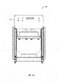
- FIG. 14 is a side view of one embodiment of an ultrasound test unit.
- FIG. 15 is a perspective view of one embodiment of a jar assembly.
- FIG. 16 is a side view of one embodiment of jar assembly.
- FIG. 17 is a top view of one embodiment of a jar assembly.
- FIG. 18 is a sectional view of one embodiment of a jar assembly taken along line A-A of FIG. 17 .
- FIG. 19 is a detail view of A of FIG. 18 .
- FIG. 20 is a detail view of B of FIG. 18 .
- FIG. 21 is a detail view of C of FIG. 18 .
- FIG. 22 is a perspective view of one embodiment of a drive assembly.
- FIG. 23 is a front view of the drive assembly of FIG. 22 .
- FIG. 24 is a perspective view of one embodiment of a drive assembly bearing housing.
- FIG. 25 is an exploded view of one embodiment of a drive assembly bearing housing.
- the present invention includes a method for ultrasonic testing that addresses problems with conventional ultrasonic testing.
- This invention allows for the probe to be immersed while the part remains dry.
- An ultrasonic probe is suspended in a liquid bath inside of a bell-jar with an elastomeric diaphragm stretched across the bottom of the bell-jar.
- the liquid on the probe side of the elastomeric diaphragm provides consistent coupling with the test piece on the other side of the elastomer.
- By applying pressure inside of the bell-jar the elastomer is forced down against the test piece surface conforming to the irregularities in the surface and providing intimate contact at all points.
- the liquid bath in which the probe resides allows the probe to be moved effortlessly across the surface of the part with no unwanted forces applied to the test piece surface. Under very light pressure the elastomeric diaphragm only applies a very slight pressure to the delicate face of the test piece while maintaining the intimate contact required to ensure a consistent ultrasonic test.
- the following diagrams depict the invention as used to inspect for internal cracking in automotive and diesel catalyst substrate. These substrates are made of ceramic or silicon carbide and are susceptible to internal cracking during manufacturing.
- the challenges in ultrasonically testing these pieces are due to the fragile nature of the parts, their inability to be immersed, their size and their typically irregular surfaces.
- Test results from ultrasonic testing may be used to characterize a test piece, identify flaws or defects in the test piece, reject test pieces, identify the absence of flaws or defects in a test or their other purposes.
- the present invention may be used in other contexts for testing of other types of test pieces, especially those which involve test pieces which are fragile in nature, have an inability to be immersed, and have irregular surfaces.
- FIG. 3 illustrates one embodiment of a bell-jar assembly applied to an test object.
- the system 30 illustrates an ultrasound bell-jar assembly 32 proximate a test object 34 .
- the test object 34 is a catalyst substrate.
- a substrate lift platform 36 is also shown for lifting the substrate 34 to the ultrasound bell-jar assembly 32 .
- the substrate lift platform 36 allows non-identical test objects to be used in the same setup.
- FIG. 3 shows the system with a part in testing.
- the bell-jar assembly 32 houses the probe and sits above the test piece 34 .
- the test piece 34 is placed on a stable lift platform 36 which lifts it into the diaphragm of the bell-jar assembly 32 . Once the part is lifted into the diaphragm, pressure is applied inside the bell jar to force the diaphragm into the face of the test piece.
- FIG. 4 illustrates another view of the ultrasound bell-jar assembly 32 where compressed air, which can be as low as one PSI, is received through an inlet 38 .
- a probe 40 within the ultrasound bell-jar assembly 32 .
- the probe 40 is placed proximate or adjacent an elastomeric diaphragm 42 .
- FIG. 5 illustrates that an ultrasonic frequency signal 48 travels through the liquid bath 44 and the pressurized diaphragm 42 and into the test piece 34 .
- the probe 40 which is located inside of the bell-jar assembly 32 is suspended in a bath of liquid 44 which provides the consistent coupling with the top side of the pressurized diaphragm 42 .
- This liquid bath 44 allows the probe 40 to be situated some distance from the diaphragm 42 and gives it the ability to move freely over the surface of the part while maintaining its ultrasonic coupling with the part. All connections to the probe 40 are fed through the center shaft which supports and stabilizes the probe in the bath 44 via a sealed bearing assembly at the top of the bell-jar (probe feed-through 46 ). Once the part is in place and the bell-jar is pressurized the probe can sweep over the part to acquire the sample.
- Other inputs into the bell-jar include fluid supply ports, pressure relief ports, and additional ports for sensing and detection devices.
- FIG. 6 provides an exploded view of the ultrasound bell-jar assembly 32 .
- the assembly 32 includes a secondary backing ring 50 and a main backing ring 52 .
- a clamp ring 54 in conjunction with nuts 58 and bolts 56 is used to secure the diaphragm 42 .
- Servicing the bell-jar and internal components is accomplished by rotating the bell-jar upside-down and removing the flange rings and the diaphragm.
- the backing rings 50 , 52 are placed to clamp the diaphragm 42 in place and to back the diaphragm 42 in locations where the piece is not in contact with the diaphragm 42 to eliminate bulging of the pressurized diaphragm 42 in unsupported regions.
- FIG. 7 is a photograph of a bell jar test showing no pressure across the face of the diaphragm.
- FIG. 8 is a photograph illustrating pressure in pressure vessel on DPF monolith substrate-notice the cell structure showing through the membrane surface.
- FIG. 9 is a photograph of pressure in the pressure vessel on segmented substrate-notice the segments and cell structure showing through the membrane surface.
- the pressure vessel may contain a liquid or gel solution which will act in conjunction with the pressurized diaphragm as the final couplant between the Ultrasonic probe and the test piece.
- FIG. 10 is a photograph illustrating the test pressure vessel with water under pressure.
- FIG. 11 is a perspective view of one embodiment of an ultrasound test unit.
- the ultrasound test unit 10 has a housing 12 .
- FIG. 12 is a top view of the ultrasound test unit 10 .
- FIG. 13 is a front view of the ultrasound test unit 10 .
- FIG. 14 is a side view of the ultrasound test unit 10 .
- FIG. 15 is a perspective view of one embodiment of a jar assembly showing the drive assembly.
- the assembly 60 includes a drive shaft 62 and a shaft collar 64 .
- a hard stop level 66 is also shown.
- a motor mount assembly 70 is shown as well as a bearing housing assembly 68 .
- FIG. 16 is a side view of one embodiment of jar assembly.
- FIG. 17 is a top view of one embodiment of a jar assembly.
- FIG. 18 is a sectional view of one embodiment of a jar assembly taken along line A-A of FIG. 17 .
- FIG. 19 is a detail view of A of FIG. 18 .
- FIG. 20 is a detail view of B of FIG. 18 .
- FIG. 21 is a detail view of C of FIG. 18 .
- FIG. 22 is a perspective view of one embodiment of a drive assembly.
- FIG. 23 is a front view of the drive assembly of FIG. 22 .
- FIG. 24 is a perspective view of one embodiment of a jar bearing housing.
- FIG. 25 is an exploded view of one embodiment of a jar bearing housing 80 .
- a bearing housing 80 is shown as well as an outer bearing spacer 82 and an inner bearing spacer 84 . There is a lower bearing spacer 86 .
- a thrust bearing 88 is shown as well as thrust washers 90 .
- a shielded ball bearing 92 is shown as well as round O-ring 94 and a second round O-ring 96 .
- a U-cup seal 98 is shown as well as a finger disk spring 100 .
- the jar assembly need not be a jar but may be another form of a pressure vessel or container.
- the liquid bath may be of any number of types of liquids. Any number of drive mechanisms may be used.
Abstract
Description
Claims (23)
Priority Applications (1)
| Application Number | Priority Date | Filing Date | Title |
|---|---|---|---|
| US12/113,695 US8225669B2 (en) | 2007-05-07 | 2008-05-01 | Immersed probe over pressurized elastomer |
Applications Claiming Priority (2)
| Application Number | Priority Date | Filing Date | Title |
|---|---|---|---|
| US91645107P | 2007-05-07 | 2007-05-07 | |
| US12/113,695 US8225669B2 (en) | 2007-05-07 | 2008-05-01 | Immersed probe over pressurized elastomer |
Publications (2)
| Publication Number | Publication Date |
|---|---|
| US20080276710A1 US20080276710A1 (en) | 2008-11-13 |
| US8225669B2 true US8225669B2 (en) | 2012-07-24 |
Family
ID=39968323
Family Applications (1)
| Application Number | Title | Priority Date | Filing Date |
|---|---|---|---|
| US12/113,695 Expired - Fee Related US8225669B2 (en) | 2007-05-07 | 2008-05-01 | Immersed probe over pressurized elastomer |
Country Status (1)
| Country | Link |
|---|---|
| US (1) | US8225669B2 (en) |
Families Citing this family (1)
| Publication number | Priority date | Publication date | Assignee | Title |
|---|---|---|---|---|
| FR2972802B1 (en) * | 2011-03-16 | 2013-09-20 | Snecma | NON-DESTRUCTIVE CONTROL SYSTEM, BY ULTRASOUND IN IMMERSION, OF PARTS |
Citations (13)
| Publication number | Priority date | Publication date | Assignee | Title |
|---|---|---|---|---|
| US2532507A (en) * | 1945-08-13 | 1950-12-05 | Acec | Feeler for elastic waves |
| US2545101A (en) * | 1947-12-19 | 1951-03-13 | Acec | Rotating diaphragm transducer for solid material testing |
| US2992553A (en) * | 1957-04-24 | 1961-07-18 | Ivan L Joy | Coupling method and apparatus for ultrasonic testing of solid bodies |
| US3251220A (en) * | 1962-06-27 | 1966-05-17 | Chemetron Corp | Apparatus for ultrasonic flaw testing |
| US3730121A (en) * | 1963-02-19 | 1973-05-01 | Us Navy | Acoustic torpedo test apparatus |
| US3798961A (en) * | 1971-02-25 | 1974-03-26 | C Flambard | Apparatus for non-destructive checking of workpieces |
| US4059098A (en) * | 1975-07-21 | 1977-11-22 | Stanford Research Institute | Flexible ultrasound coupling system |
| US4237901A (en) * | 1978-08-30 | 1980-12-09 | Picker Corporation | Low and constant pressure transducer probe for ultrasonic diagnostic system |
| USH1290H (en) * | 1992-08-26 | 1994-02-01 | The United States Of America As Represented By The Secretary Of The Army | Conformable acoustic coupler |
| US5419195A (en) * | 1993-04-30 | 1995-05-30 | Westinghouse Electric Corporation | Ultrasonic booted head probe for motor bore inspection |
| US5585565A (en) * | 1993-07-06 | 1996-12-17 | Tuboscope Vetco International, Inc. | Method for the ultrasonic inspection of pipe and tubing and a transducer assembly for use therewith |
| US7481115B2 (en) * | 2003-03-31 | 2009-01-27 | Panasonic Corporation | Ultrasonic probe |
| US7614304B2 (en) * | 2006-05-16 | 2009-11-10 | Corning Incorporated | Ultrasonic testing system and method for ceramic honeycomb structures |
-
2008
- 2008-05-01 US US12/113,695 patent/US8225669B2/en not_active Expired - Fee Related
Patent Citations (13)
| Publication number | Priority date | Publication date | Assignee | Title |
|---|---|---|---|---|
| US2532507A (en) * | 1945-08-13 | 1950-12-05 | Acec | Feeler for elastic waves |
| US2545101A (en) * | 1947-12-19 | 1951-03-13 | Acec | Rotating diaphragm transducer for solid material testing |
| US2992553A (en) * | 1957-04-24 | 1961-07-18 | Ivan L Joy | Coupling method and apparatus for ultrasonic testing of solid bodies |
| US3251220A (en) * | 1962-06-27 | 1966-05-17 | Chemetron Corp | Apparatus for ultrasonic flaw testing |
| US3730121A (en) * | 1963-02-19 | 1973-05-01 | Us Navy | Acoustic torpedo test apparatus |
| US3798961A (en) * | 1971-02-25 | 1974-03-26 | C Flambard | Apparatus for non-destructive checking of workpieces |
| US4059098A (en) * | 1975-07-21 | 1977-11-22 | Stanford Research Institute | Flexible ultrasound coupling system |
| US4237901A (en) * | 1978-08-30 | 1980-12-09 | Picker Corporation | Low and constant pressure transducer probe for ultrasonic diagnostic system |
| USH1290H (en) * | 1992-08-26 | 1994-02-01 | The United States Of America As Represented By The Secretary Of The Army | Conformable acoustic coupler |
| US5419195A (en) * | 1993-04-30 | 1995-05-30 | Westinghouse Electric Corporation | Ultrasonic booted head probe for motor bore inspection |
| US5585565A (en) * | 1993-07-06 | 1996-12-17 | Tuboscope Vetco International, Inc. | Method for the ultrasonic inspection of pipe and tubing and a transducer assembly for use therewith |
| US7481115B2 (en) * | 2003-03-31 | 2009-01-27 | Panasonic Corporation | Ultrasonic probe |
| US7614304B2 (en) * | 2006-05-16 | 2009-11-10 | Corning Incorporated | Ultrasonic testing system and method for ceramic honeycomb structures |
Also Published As
| Publication number | Publication date |
|---|---|
| US20080276710A1 (en) | 2008-11-13 |
Similar Documents
| Publication | Publication Date | Title |
|---|---|---|
| EP1448983B1 (en) | Coupling element with a varying wall thickness for an ultrasound probe | |
| US7395714B2 (en) | Magnetically attracted inspecting apparatus and method using a ball bearing | |
| US20050126293A1 (en) | Cylindrically-rotating ultrasonic phased array inspection method for resistance spot welds | |
| CN106770682B (en) | Ultrasonic probe capable of automatically filling coupling agent | |
| US20120053856A1 (en) | Low profile encircling ultrasonic probe for the inspection of in-situ piping in immersion mode | |
| US20210356439A1 (en) | System, Method and Apparatus for Ultrasonic Inspection | |
| US8225669B2 (en) | Immersed probe over pressurized elastomer | |
| US20020068872A1 (en) | Ultrasonic horn assembly | |
| US20090084183A1 (en) | Slip ring positive z force liquid isolation fixture permitting zero net force on workpiece | |
| US6085591A (en) | Immersion testing porous semiconductor processing components | |
| JP3709559B2 (en) | Dry contact high frequency ultrasonic transmission method and apparatus therefor, and dry contact high frequency ultrasonic inspection method and apparatus therefor | |
| JP2005351723A (en) | Ultrasonic flaw detector | |
| US10473627B2 (en) | Portable acoustic apparatus for in-situ monitoring of a workpiece | |
| JP6573184B2 (en) | Infrared defect detection system using ultrasonic waves | |
| KR101654296B1 (en) | Ultrasonography probe with piezoelectric element | |
| CN218099014U (en) | Ultrasonic detection device | |
| JP2022162798A (en) | Ultrasonic inspection device and inspection method | |
| JP2005043107A (en) | Ultrasonic image inspection device | |
| JPH09257758A (en) | Water immersion type ultrasonic flaw inspection method | |
| WO2001046714A1 (en) | Ultrasonic horn assembly | |
| CN207232095U (en) | A kind of ultrasonic probe scanning equipment of pressure adjustable | |
| CN113070809B (en) | Method and apparatus for detecting polishing pad of chemical mechanical polishing apparatus | |
| CN214041253U (en) | High-end composite textile material's detection device | |
| EP1393821A1 (en) | Ultrasonic transducer | |
| WO2023035085A1 (en) | Enhanced coverage local immersion for non-destructive test (ndt) |
Legal Events
| Date | Code | Title | Description |
|---|---|---|---|
| AS | Assignment |
Owner name: REFLECT SCIENTIFIC (DBA) MIRALOGIX, MONTANA Free format text: ASSIGNMENT OF ASSIGNORS INTEREST;ASSIGNOR:PIERSON, ERIC;REEL/FRAME:020916/0159 Effective date: 20080428 |
|
| AS | Assignment |
Owner name: CAMRIX ENGINEERING CORPORATION, MONTANA Free format text: ASSIGNMENT OF ASSIGNORS INTEREST;ASSIGNOR:REFLECT SCIENTIFIC, INC.;REEL/FRAME:024710/0281 Effective date: 20100518 Owner name: NEW GATE TECHNOLOGIES, MONTANA Free format text: ASSIGNMENT OF ASSIGNORS INTEREST;ASSIGNOR:CAMRIX ENGINEERING CORPORATION;REEL/FRAME:024710/0285 Effective date: 20100526 |
|
| REMI | Maintenance fee reminder mailed | ||
| LAPS | Lapse for failure to pay maintenance fees | ||
| STCH | Information on status: patent discontinuation |
Free format text: PATENT EXPIRED DUE TO NONPAYMENT OF MAINTENANCE FEES UNDER 37 CFR 1.362 |
|
| FP | Lapsed due to failure to pay maintenance fee |
Effective date: 20160724 |