US8225251B2 - Circuit states - Google Patents
Circuit states Download PDFInfo
- Publication number
- US8225251B2 US8225251B2 US12/694,199 US69419910A US8225251B2 US 8225251 B2 US8225251 B2 US 8225251B2 US 69419910 A US69419910 A US 69419910A US 8225251 B2 US8225251 B2 US 8225251B2
- Authority
- US
- United States
- Prior art keywords
- net
- equation
- analyzer
- truthfulness
- state
- Prior art date
- Legal status (The legal status is an assumption and is not a legal conclusion. Google has not performed a legal analysis and makes no representation as to the accuracy of the status listed.)
- Active, expires
Links
- 238000000034 method Methods 0.000 claims abstract description 36
- 238000006467 substitution reaction Methods 0.000 claims description 14
- 238000011156 evaluation Methods 0.000 claims description 4
- 230000014509 gene expression Effects 0.000 description 27
- 238000007667 floating Methods 0.000 description 20
- 238000010276 construction Methods 0.000 description 4
- 238000010586 diagram Methods 0.000 description 4
- 238000013459 approach Methods 0.000 description 3
- 230000006870 function Effects 0.000 description 3
- 238000012986 modification Methods 0.000 description 3
- 230000004048 modification Effects 0.000 description 3
- 230000009467 reduction Effects 0.000 description 3
- 238000012552 review Methods 0.000 description 3
- 238000005516 engineering process Methods 0.000 description 2
- 230000008569 process Effects 0.000 description 2
- 230000004044 response Effects 0.000 description 2
- 238000004088 simulation Methods 0.000 description 2
- PPASLZSBLFJQEF-RKJRWTFHSA-M sodium ascorbate Substances [Na+].OC[C@@H](O)[C@H]1OC(=O)C(O)=C1[O-] PPASLZSBLFJQEF-RKJRWTFHSA-M 0.000 description 2
- 238000012360 testing method Methods 0.000 description 2
- 230000009471 action Effects 0.000 description 1
- 230000000694 effects Effects 0.000 description 1
- 230000005669 field effect Effects 0.000 description 1
- 238000013100 final test Methods 0.000 description 1
- 238000013101 initial test Methods 0.000 description 1
- 229910044991 metal oxide Inorganic materials 0.000 description 1
- 150000004706 metal oxides Chemical class 0.000 description 1
- 239000004065 semiconductor Substances 0.000 description 1
- 235000013599 spices Nutrition 0.000 description 1
- 230000036962 time dependent Effects 0.000 description 1
- 238000012546 transfer Methods 0.000 description 1
- 238000011144 upstream manufacturing Methods 0.000 description 1
Images


Classifications
-
- G—PHYSICS
- G06—COMPUTING; CALCULATING OR COUNTING
- G06F—ELECTRIC DIGITAL DATA PROCESSING
- G06F30/00—Computer-aided design [CAD]
- G06F30/30—Circuit design
- G06F30/32—Circuit design at the digital level
- G06F30/33—Design verification, e.g. functional simulation or model checking
- G06F30/3323—Design verification, e.g. functional simulation or model checking using formal methods, e.g. equivalence checking or property checking
-
- G—PHYSICS
- G06—COMPUTING; CALCULATING OR COUNTING
- G06F—ELECTRIC DIGITAL DATA PROCESSING
- G06F30/00—Computer-aided design [CAD]
- G06F30/30—Circuit design
- G06F30/36—Circuit design at the analogue level
- G06F30/367—Design verification, e.g. using simulation, simulation program with integrated circuit emphasis [SPICE], direct methods or relaxation methods
Definitions
- Embodiments of the present invention relate in general to the field of circuits.
- Floating gates are a risk in the circuit industry, for one floating gate may cause reduced functionality or permanently kill a circuit.
- One approach to resolving floating gates is to predict and/or detect floating gates using a time domain simulation. Unfortunately, time domain simulations may not always determine if a gate floats. What is needed is a more accurate way to determine if a gate floats.
- the method comprises deriving a net equation representing a net state of an analog circuit net, wherein the net equation is derived from at least one other net state, determining a truthfulness of the net equation, reporting the truthfulness.
- FIG. 1 illustrates a net analyzer upon which embodiments of the present invention may be implemented.
- FIG. 2 illustrates an example to show that a net may not float, upon which embodiments of the present invention may be implemented.
- FIG. 3 illustrates an example to show that a net may float, upon which embodiments of the present invention may be implemented.
- FIG. 4 illustrates another example to show that a net may not float, upon which embodiments of the present invention may be implemented.
- FIG. 5 illustrates an example for detecting floating nets by combining multiple devices on a single net, upon which embodiments of the present invention may be implemented.
- FIG. 6 is a diagram of a tree of a method for detecting floating nets, upon which embodiments of the present invention may be implemented.
- FIG. 7 is a logic diagram of a method for detecting floating nets, upon which embodiments of the present invention may be implemented.
- FIG. 8 is a flow chart of a method for detecting floating nets, upon which embodiments of the present invention may be implemented.
- FIG. 9 illustrates a server, upon which embodiments of the present invention may be implemented.
- a net analyzer is discussed.
- the net analyzer may be used to determine if a transistor gate floats by determining if a net, electrically coupled to the gate, floats.
- the net is determined to float or not to float by using net equations.
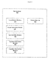
- FIG. 1 illustrates a net analyzer 100 upon which embodiments of the present invention may be implemented.
- the net analyzer 100 comprises an input/output module 110 , a circuit construction module 120 , a net identifier module 130 , a net equation allocation module 140 , a net equation resolution module 150 , and a history module 160 .
- modules of the net analyzer 100 are merged and/or performed outside the net analyzer 100 .
- the input/output module 110 receives circuit configuration information and returns circuit, node and/or net information to a user.
- the circuit information contains a netlist and/or information regarding a circuit, such as specifications and configurations of nodes, nets, and the like.
- the circuit information may be in a standard format, such as SPICE, or any other format that has specification entries for nodes, nets, and the like.
- the returning information may be formatted for use in a spreadsheet, for display on a terminal, and the like.
- the circuit construction module 120 receives the circuit information from the input/output module 110 .
- the circuit construction module 120 converts circuit information to an internal circuit.
- the internal circuit is a memory footprint of nets, pins, devices, and the like.
- the net analyzer 100 traverses and queries the internal circuit to obtain objects and/or information as needed. For example, nets from a netlist are placed in memory, associated with names from the netlist, and coupled with relevant device connections also from the netlist.
- the net identifier module 130 identifies net that may potentially float and/or are susceptible to float.
- the net identifier module 130 determines a potential to float by querying the circuit construction module 120 to determine which nets are connected to MOS gates, have constant connections, such as a power tie, and the like.
- a net with only MOS gates connections has a potential to float.
- a net with a connection to a constant power tie will not float, thereby making a test for floating unnecessary.
- a net with connections to MOS gates and other devices, such as resistors, and the like, may have a potential to float.
- the net identifier module 130 determines one or more nets that have a potential to float, the nets are mapped to equations to determine if they may float, as discussed herein. In another embodiment, nets are mapped after the net identifier module 130 determines has finished determine the float potential of the nets.
- the equation allocation module 140 receives a net from the net analyzer 100 to be characterized with a net equation.
- the net equation represents a proposed net state using one or more states of other nets.
- the proposed net state and the one or more states of other nets are float/floating, high, or low.
- Net 1 is postulated to float (equal to Z) if and only if Net 2 is low (equal to 0) and Net 3 is high (equal to 1).
- a net state is determined by the equation resolution module 150 discussed below.
- the equation resolution module 150 determines net states and resolves net equations. In one embodiment, the equation resolution module 150 communicates with the equation allocation module and the net identifier module 130 . In another embodiment, the equation resolution module 150 communicates with the net analyzer 100 . The equation resolution module 150 resolves a net equation by determining and/or resolving any logic combined with other net states in the equation. In one embodiment, a net equation is resolved by determined if the proposed net state is either true or false. For example, if the proposed net state is to float, and a basis to obtain a “float” is satisfied, then a net equation is resolved to be true, that is, the net may float.
- a net state in addition to “true” and “false” a net state is resolved as “possible.”
- the possible resolution may be assigned to a net state when certain conditions occur, such a time-out or time limit, a temporarily unresolved net equation, a depth limit, a branch limit, and the like.
- the certain conditions may be identified as a predetermined event.
- a forced stop that is the time-out and/or time limit, may be user predetermined prior to the net analyzer 100 receiving circuit configuration information.
- the time-out is determined on the fly via user response to a prompt, conditionally based, such as a complexity of a net equation, and the like.
- the temporarily unresolved net equation may be later resolved by additional user input, the net analyzer 100 making assumptions, such as forcing values to net states, and/or removing previously determined “suspicious” nets from the net equation.
- a suspicious net is a net that the net analyzer 100 identifies as a potential floating net and may be reported to the user.
- the history module 160 stores net state information.
- the net state information contains information resolved by the equation resolution module 150 .
- the history module 160 communicates with the equation allocation module 140 to simplify the net equation.
- One simplification may be substitution of the resolved net state in place of the net state. For example, instead of added Net B equals “high” (the net state), insert “true” (the resolution of the net state) into the equation.
- the history module 160 communicates with the equation resolution module 150 , whereby the equation resolution module queries the history module 160 for previous net state resolutions. Net equations and net equation resolution are discussed with respect to FIGS. 2-4 and 7 , and further herein.
- the net identifier module 130 , the equation allocation module 140 , the equation resolution module 150 , and the history module 160 are combined into one or more modules. In another embodiment, the equation resolution module 150 and the history module 160 are combined into one module. It will be recognized by one of ordinary skill in the art that any combination of modules within the net analyzer 100 may be practiced without specific details of the functions within the modules, and is included within the spirit and scope of the embodiments.
- FIG. 2 illustrates an example 200 to show that a net may not float, upon which embodiments of the present invention may be implemented.
- the example 300 shows Net A 201 coupled to device 210 and device 220 , Net B 202 coupled to device 210 , Net C 203 coupled to device 220 , and Net D 204 coupled to device 210 , device 220 and device 230 .
- the net analyzer 100 determines that a gate of device 230 is coupled to the Net D 204 , wherein the Net D 204 is coupled to devices that have varying states, and thereby may “suspect” that the gate of device 230 may float.
- [Net B Z] (b)
- [Net C Z] (c)
- the net analyzer 100 evaluates expression (d) as a contradiction, thereby concluding that the proposed network state of “float” is false, that is, the gate of device 230 may never float.
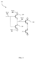
- FIG. 3 illustrates an example 300 to show that a net may float, upon which embodiments of the present invention may be implemented.
- the example 300 shows Net E 301 coupled to device 310 and device 330 , Net F 302 coupled to device 310 , Net G 303 coupled to devices 320 - 330 and device 350 , Net H 304 coupled to device 310 and device 320 , Net J 305 coupled to device 320 and devices 340 - 350 , and Net K 306 coupled to device 350 .
- the net analyzer 100 determines that a gate of device 340 is coupled to the Net J 305 , wherein the Net J 305 is coupled to devices that have varying states, and thereby may “suspect” that the gate of device 340 may float.
- [Net H Z] (f)
- the net analyzer 100 refers to a logic table and/or a lookup table (not depicted).
- Some logic devices represented in the lookup table include, a PFET, an NFET, a PFET diode, an NFET diode, a resistor, and the like.
- the lookup table contains conditions for logic devices to obtain a specific output.
- a and B represent abstract names, “1” is high and “0” is low and “z” represents “float.”
- G is a gate.
- G z).
- G 0
- G z.
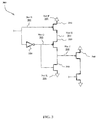
- FIG. 4 illustrates another example 400 to show that a net may not float, upon which embodiments of the present invention may be implemented.
- the example 400 shows Net M 401 coupled to device 410 and device 420 , Net N 402 coupled to devices 420 - 430 and device 480 , Net P 403 coupled to device 430 and device 440 , Net R 404 coupled to device 430 and devices 460 - 470 , Net S 405 coupled to device 440 and device 460 , and Net T 406 coupled to device 460 and device 480 .
- the net analyzer 100 determines an input to device 470 is suspect, and therefore analyzes Net R 404 .
- [Net T 0] (k)
- the net analyzer 100 notices that these conflicting terms were “ANDed” without any other possible OR terms, the existence of variable of “Net N 402 ” in the equation (k) is necessary, and thus may not be reduced, thereby disproving the hypothesis that Net R 404 may float.
- the net analyzer 100 proves, in example 400 , a net may be in a configuration whereby the net never floats.
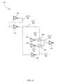
- FIG. 5 illustrates an example 500 for detecting floating nets by combining multiple devices on a single net, upon which embodiments of the present invention may be implemented.
- the example 500 shows Net 505 coupled to a PFET 510 , a PFET 520 , an NFET 530 , an NFET 540 , and a resistor 550 .
- the net analyzer 100 when the net analyzer 100 analyzes a net, the net analyzer 100 considers combinations of several devices based on a lookup table and based on a type of device coupled to the net.
- PFET 520 1
- Resistor 550 1, as any PFET or resistor may pull high.
- the net analyzer 100 does not use expressions for the NFETs 530 - 540 , as the NFET may only pull the Net 505 to 0, and the net analyzer 100 is “optimistic” by looking at every combination where the Net 505 may be high. Additionally, by not including the NFETs, the net analyzer 100 has fewer expressions in the equation.
- NFET 540 0
- Resistor 550 0, as any NFET or any resistor may pull low. In this situation, the net analyzer 100 does not use expressions for the PFETs 510 - 520 , as an “optimistic” approach is used, discussed above.
- the net analyzer needs to account for all devices that may pull up or down, and as such, needs to check for all devices to be off and/or float.
- the net analyzer 100 determines if any of the FETs are wired as diodes.
- a diode can pull 1/0 only if other opposing paths are off, as a diode is a weak bleeder path.
- [PFET 520 1]
- [Resistor 550 1]
- [Resistor 550 z]]
- [NFET 540 0]
- [Resistor 550 0]
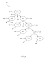
- FIG. 6 is a diagram of a tree 600 of a method for detecting floating nets, upon which embodiments of the present invention may be implemented.
- the tree 600 comprises nodes, such as node 610 , relationships, such as relationship 612 , and expressions, such as expression 614 .
- the tree 600 is used to illustrate logic expressions, node relationships, and the like.
- the relationships couple two or more nodes.
- the relationship 612 couples node 610 and node 625 .
- the expressions are logic dispositions.
- the tree 600 expands from node 610 , a top node, downward as the net analyzer 100 resolves a hypothesis.
- the top node, the node 610 , of the tree 600 contains a hypothesis.
- C z )
- the net analyzer 100 continues exploring by expanding branches until the tree 600 becomes too large to manage, whereby the net analyzer 100 resolves the hypothesis as a virtual truth.
- a virtual truth is assumed as a truth for practical purposes.
- the net analyzer 100 may determine if the tree 600 is too large to manage based on computer resources, such as memory or CPU speed, and the like, a predetermined user input, such as a time, and/or based on circuit response characteristics, such as exploring further if fewer or more instances where the hypothesis is not resolved. For example, if during final testing of a circuit, a user requests fewer virtual truths, as opposed to allowing for more virtual truths during initial testing of a circuit.
- the conflict may block the logic of the tree 600 , and prevent a true from reaching the root. If no other path exist for a true to propagate up without the conflict, then the circuit is proven false, that is the hypothesis is false, and for the tree 600 , net C can not float.
- FIG. 7 is a logic diagram of a method for detecting floating nets, upon which embodiments of the present invention may be implemented.
- the net analyzer 100 determines a net to analyze. The determination may be based on suspect nodes, as discussed herein, methodical, or user defined, such as looking at a particular section of a circuit.
- the net analyzer 100 develops a net equation to represent a state based on a hypothesis, as discussed herein.
- the net analyzer 100 determines if the net equation is reducible, as discussed herein. If the net equation is reducible, then the net equation is reduced at 725 and loops back to check if the net equation may be reduced again at 720 . If the net equation is not reducible, at this time, the net analyzer 100 determines, at 730 , if a substitute expression may be made, as discussed herein. If a substitute expression may be made, the net analyzer substitutes an expression at 735 . If the substitution is made, the net analyzer 100 checks again to determine if the net equation is reducible at 720 .
- the net analyzer 100 determines if the net equation has been resolved at 740 , that is has the hypothesis been proved or disproved, as discussed herein. If the equation has been resolved, information is stored at 745 , as discussed here. If the equation has not been resolved, at 750 the net analyzer 100 determines if a forced stop (a predetermined event) is justified, as discussed herein. If the forced stop is not justified, the net analyzer 100 explores another node and develops another net equation at 715 , and continues the process. If the net analyzer 100 determines a forced stop is justified, then the net analyzer 100 stores net information at 755 , reports forced stop information and any net state information at 760 .
- a forced stop a predetermined event
- the net analyzer 100 determines if another net is to be analyzed. If another net is to be analyzed, the net analyzer 100 determines another net equation at 710 , and repeats the process until the net analyzer 100 determines there are no more nets to analyze. After the net analyzer 100 determines there are no more nets to analyzer, the net analyzer 100 reports to the user, such as net information, floating nets and/or gates, suspect nets and/or gates, iterations and complexity of net equations, and the like.
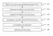
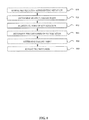
- FIG. 8 is a flow chart of a method for detecting floating nets, upon which embodiments of the present invention may be implemented.
- the net analyzer 100 derives a net equation representing a net state of an analog circuit net.
- the net equation is derived from at least one other net state, as discussed herein.
- the net analyzer 100 determines a suspect failure point prior to determining the truthfulness of the net equation.
- the suspect failure point is determined based on device configuration, as discussed herein.
- the net analyzer resolves the net equation making substitutions, reductions and other approaches as explained in FIG. 7 and herein.
- the net analyzer 100 may substitute terms based on a previously identified configuration of devices, and/or previously defined set of devices/configuration.
- the previously identified configuration may be identified during a previous review of the same devices in a prior resolution of a different net equation or a prior branch of the same net equation.
- the previously defined set of devices/configuration may be pre-assigned by a user. For example, a user defines a configuration of diodes, a PMOS and a NMOS to have a particular net state.
- the net analyzer resolves the net equation and determines the next course of action.
- the net analyzer 100 determines the truthfulness of the net equation, as defined in FIG. 7 and herein. After the net equation is resolved and the truthfulness determined, the net analyzer 100 tests the hypothesis to determine any circuit issues, such as a failure point.
- the net analyzer 100 determines a failure point.
- a user may identify a potential failure point and request the net analyzer 100 to determine is the potential failure point is a failure point.
- a failure point is any point, net or device that will cause an analog circuit to fail, and/or generate an unexpected result. Some examples of failures or unexpected results are memory leaks, shorts, accessing floating values, and the like.
- the net analyzer 100 determines and reports failure points independent of any user identified potential failure points, that is the net analyzer 100 review the entire circuit and determines any and/or all failure points.
- a truthfulness indicated a failure point for example, if Net M floats, and the net analyzer 100 determines Net M to float (a true hypothesis), then the net analyzer determines the truthfulness to be a failure point.
- the failure point is determined with one evaluation of the net equation.
- the net analyzer 100 may determine a failure point for one evaluation of one net equation, where the evaluation may take several iterations of the substitutions, reductions, and the like, as detailed in FIG. 7 and herein.
- the failure point is determined with a certainty of 100%.
- the net analyzer 100 may determine 100% certainty, because a hypothesis may be determined to be true or false with no uncertainty. This is unlike other circuit analyzers that are time dependent, where an analysis is performed with an estimated certainty, such as 99.99%, as determined by a time and/or cycle iteration variable wherein a circuit does not fail.
- the net analyzer 100 uses a hypothesis to determine a net equation, the net analyzer 100 resolves net equations and determines failure points independent of a time domain variable. In various embodiments, the net analyzer 100 determines all the failure points in an analog circuit.
- the net analyzer 100 determines failure points with only a user input of power rail definitions.
- a power rail definition is defining a power to a specific voltage or range of voltages, such as a range of ⁇ 1 to +2 ivolts.
- the user defines input/output voltages and/or currents of one or more devices and/or power rails.
- the net analyzer 100 predicts a certain net state will not occur. For example, the net analyzer 100 predicts and determines a net will not float, and/or not be a failure point. In various embodiments, the net analyzer 100 determines and/or predicts a device state signal is float, on or off. Depending on the device type, the net analyzer 100 predicts, based on net equation resolution, the device state. For example, the net analyzer 100 predicts and determines a PMOS to be on.
- the net analyzer 100 reports the truthfulness and/or failure points to the user, as discussed herein. Based on the user requirements, and/or the net analyzer 100 , reports may vary to report failure points, net states, potential failure points, and the like. Potential failure points may occur when a net equation of not resolved definitely, but when a predetermined event, such as a forced stop, occurs, as discussed herein.
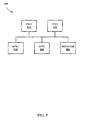
- FIG. 9 illustrates a server 900 , upon which embodiments of the present invention may be implemented.
- the server 900 comprises an application 910 , and a storage device 920 .
- the application 910 is configured to run on the server, and configured to perform the functions of the net analyzer 100 .
- the storage device 920 is configured to store information, such as net states, net configurations, and/or any other information used for a determination of the social metrics.
- the server 900 contains a computer readable medium having embodied thereon a program, the program being executable by a computing device for performing a method for social capital determination and use.
- the program is configured to receive circuit configuration information from a user; and return net state information to the user.
- the net analyzer 100 may operate remotely or be accessed via a network.
- the net analyzer 100 may access multiple CPU located on different computers to perform net state analysis. Therefore, the above description should not be taken as limiting the scope of the invention which is defined by the appended claims.
Abstract
Description
Net D=Z if [
-
- wherein Z equals “float”
[
[
[[Net A=high]|[Net B=Z]]&[[Net A=low]|[Net C=Z]]
[Net A=high]&[Net A=low] (d)
Net J=Z if [
[
[device 350=Z] if [Net G=low] (g)
[[Net G=high]|[Net H=Z]]&[[Net G=low]] (h)
[Net H=Z]&[Net G=low] (i)
[Net E=high]&[Net E=high] (j)
[Net P=Z]|[Net N=0]&[Net S=Z]|[Net T=0] (k)
[[PFET 510=1]&[
[[
C=z(hypothesis)
C=z if B=0&E=1
E=1 if F=0|D=z
D=z if A=0&(B=0|C=z)
Claims (20)
Priority Applications (4)
| Application Number | Priority Date | Filing Date | Title |
|---|---|---|---|
| US12/694,199 US8225251B2 (en) | 2009-06-02 | 2010-01-26 | Circuit states |
| US13/345,721 US8484590B2 (en) | 2009-06-02 | 2012-01-08 | Method of predicting electronic circuit floating gates |
| US13/401,704 US8504957B2 (en) | 2009-06-02 | 2012-02-21 | Automated identification of power and ground nets in an integrated circuit netlist |
| US13/936,354 US8881076B2 (en) | 2009-06-02 | 2013-07-08 | Method of predicting contention between electronic circuit drivers |
Applications Claiming Priority (2)
| Application Number | Priority Date | Filing Date | Title |
|---|---|---|---|
| US18340509P | 2009-06-02 | 2009-06-02 | |
| US12/694,199 US8225251B2 (en) | 2009-06-02 | 2010-01-26 | Circuit states |
Related Parent Applications (1)
| Application Number | Title | Priority Date | Filing Date |
|---|---|---|---|
| US13/401,704 Continuation-In-Part US8504957B2 (en) | 2009-06-02 | 2012-02-21 | Automated identification of power and ground nets in an integrated circuit netlist |
Related Child Applications (1)
| Application Number | Title | Priority Date | Filing Date |
|---|---|---|---|
| US13/345,721 Continuation-In-Part US8484590B2 (en) | 2009-06-02 | 2012-01-08 | Method of predicting electronic circuit floating gates |
Publications (2)
| Publication Number | Publication Date |
|---|---|
| US20100306608A1 US20100306608A1 (en) | 2010-12-02 |
| US8225251B2 true US8225251B2 (en) | 2012-07-17 |
Family
ID=43221663
Family Applications (1)
| Application Number | Title | Priority Date | Filing Date |
|---|---|---|---|
| US12/694,199 Active 2030-10-12 US8225251B2 (en) | 2009-06-02 | 2010-01-26 | Circuit states |
Country Status (1)
| Country | Link |
|---|---|
| US (1) | US8225251B2 (en) |
Cited By (7)
| Publication number | Priority date | Publication date | Assignee | Title |
|---|---|---|---|---|
| US20120110528A1 (en) * | 2009-06-02 | 2012-05-03 | Jesse Conrad Newcomb | Method of predicting electronic circuit floating gates |
| US20120266121A1 (en) * | 2011-04-17 | 2012-10-18 | Jesse Conrad Newcomb | Method to determine high level power distribution and interface problems in complex integrated circuits |
| US20120266122A1 (en) * | 2011-04-17 | 2012-10-18 | Insight Eda, Inc. | Method and system of automatically identifying level shifter circuits |
| US20130298093A1 (en) * | 2009-06-02 | 2013-11-07 | Jesse Conrad Newcomb | Method of Predicting Contention Between Electronic Circuit Drivers |
| US10853543B1 (en) * | 2019-03-29 | 2020-12-01 | Jesse Conrad Newcomb | Logical detection of electronic circuit power sequence risks |
| US10878149B1 (en) | 2019-05-16 | 2020-12-29 | Jesse Conrad Newcomb | Logical detection of high impedance floating FET gates |
| US11233046B1 (en) | 2019-03-29 | 2022-01-25 | Jesse Conrad Newcomb | Logical detection of electronic circuit power sequence risks |
-
2010
- 2010-01-26 US US12/694,199 patent/US8225251B2/en active Active
Non-Patent Citations (2)
| Title |
|---|
| Hubner et al., "Deformable Radial Basis Functions", 2007, J. Marques de Sa et al., ICANN 2007, Part I, LNCS 4668, pp. 411-420. * |
| Tricas et al.,"Using Linear Programming and the Petri Net Structure for Deadlock Prevention in Sequential Source Allocation Systems", 2005, Actas de las XIII Jornadas de Concurrencia y Systems Distribuidos, pp. 65-77. * |
Cited By (10)
| Publication number | Priority date | Publication date | Assignee | Title |
|---|---|---|---|---|
| US20120110528A1 (en) * | 2009-06-02 | 2012-05-03 | Jesse Conrad Newcomb | Method of predicting electronic circuit floating gates |
| US8484590B2 (en) * | 2009-06-02 | 2013-07-09 | Jesse Conrad Newcomb | Method of predicting electronic circuit floating gates |
| US20130298093A1 (en) * | 2009-06-02 | 2013-11-07 | Jesse Conrad Newcomb | Method of Predicting Contention Between Electronic Circuit Drivers |
| US20120266121A1 (en) * | 2011-04-17 | 2012-10-18 | Jesse Conrad Newcomb | Method to determine high level power distribution and interface problems in complex integrated circuits |
| US20120266122A1 (en) * | 2011-04-17 | 2012-10-18 | Insight Eda, Inc. | Method and system of automatically identifying level shifter circuits |
| US8504968B2 (en) * | 2011-04-17 | 2013-08-06 | Jesse Conrad Newcomb | Method to determine high level power distribution and interface problems in complex integrated circuits |
| US8595660B2 (en) * | 2011-04-17 | 2013-11-26 | Jesse Conrad Newcomb | Method and system of automatically identifying level shifter circuits |
| US10853543B1 (en) * | 2019-03-29 | 2020-12-01 | Jesse Conrad Newcomb | Logical detection of electronic circuit power sequence risks |
| US11233046B1 (en) | 2019-03-29 | 2022-01-25 | Jesse Conrad Newcomb | Logical detection of electronic circuit power sequence risks |
| US10878149B1 (en) | 2019-05-16 | 2020-12-29 | Jesse Conrad Newcomb | Logical detection of high impedance floating FET gates |
Also Published As
| Publication number | Publication date |
|---|---|
| US20100306608A1 (en) | 2010-12-02 |
Similar Documents
| Publication | Publication Date | Title |
|---|---|---|
| US8225251B2 (en) | Circuit states | |
| US6931611B2 (en) | Design verification system for avoiding false failures and method therefor | |
| US8161439B2 (en) | Method and apparatus for processing assertions in assertion-based verification of a logic design | |
| JP5022453B2 (en) | Method, system, and computer program for analyzing timing design of an integrated circuit | |
| US8484590B2 (en) | Method of predicting electronic circuit floating gates | |
| US8930864B2 (en) | Method of sharing and re-using timing models in a chip across multiple voltage domains | |
| US10169527B2 (en) | Accurate statistical timing for boundary gates of hierarchical timing models | |
| US8201120B2 (en) | Timing point selection for a static timing analysis in the presence of interconnect electrical elements | |
| US8881076B2 (en) | Method of predicting contention between electronic circuit drivers | |
| US10169508B2 (en) | Efficient deployment of table lookup (TLU) in an enterprise-level scalable circuit simulation architecture | |
| US7506284B2 (en) | Event driven switch level simulation method and simulator | |
| US7636903B2 (en) | Device and method for testing an electric circuit | |
| Dahlgren et al. | Efficient modeling of switch-level networks containing undetermined logic node states | |
| US6631506B1 (en) | Method and apparatus for identifying switching race conditions in a circuit design | |
| US20090144044A1 (en) | Logic simulator and logic simulation method | |
| Kim et al. | Statistical analysis of simultaneous switching output (SSO) impacts on steady state output responses and signal integrity | |
| US9607117B2 (en) | Method and apparatus for calculating delay timing values for an integrated circuit design | |
| US10878151B1 (en) | Glitch occurring point detection apparatus and method | |
| US10041993B2 (en) | Safe operating area checking method and apparatus | |
| US6975972B1 (en) | Dynamic association of equations to unknowns during simulations of systems described by hardware description languages | |
| US6523152B1 (en) | Framework for rules checking utilizing resistor, nonresistor, node and small node data structures | |
| US6539346B1 (en) | Method for the electric dynamic simulation of VLSI circuits | |
| US20020112215A1 (en) | Method and system for finding static NAND and NOR gates within a circuit and identifying the constituent FETs each gate | |
| Nguyen | Web application testing beyond tactics | |
| US7124393B1 (en) | System and method for processing configuration information |
Legal Events
| Date | Code | Title | Description |
|---|---|---|---|
| STCF | Information on status: patent grant |
Free format text: PATENTED CASE |
|
| FPAY | Fee payment |
Year of fee payment: 4 |
|
| MAFP | Maintenance fee payment |
Free format text: PAYMENT OF MAINTENANCE FEE, 8TH YR, SMALL ENTITY (ORIGINAL EVENT CODE: M2552); ENTITY STATUS OF PATENT OWNER: SMALL ENTITY Year of fee payment: 8 |
|
| AS | Assignment |
Owner name: INSIGHT EDA, INC., MASSACHUSETTS Free format text: ASSIGNMENT OF ASSIGNORS INTEREST;ASSIGNOR:NEWCOMB, JESSE CONRAD;REEL/FRAME:064130/0285 Effective date: 20230630 |
|
| AS | Assignment |
Owner name: SIEMENS INDUSTRY SOFTWARE INC., TEXAS Free format text: MERGER AND CHANGE OF NAME;ASSIGNORS:INSIGHT EDA, INC.;SIEMENS INDUSTRY SOFTWARE INC.;REEL/FRAME:066371/0463 Effective date: 20231207 |
|
| FEPP | Fee payment procedure |
Free format text: 11.5 YR SURCHARGE- LATE PMT W/IN 6 MO, LARGE ENTITY (ORIGINAL EVENT CODE: M1556); ENTITY STATUS OF PATENT OWNER: LARGE ENTITY Free format text: ENTITY STATUS SET TO UNDISCOUNTED (ORIGINAL EVENT CODE: BIG.); ENTITY STATUS OF PATENT OWNER: LARGE ENTITY |
|
| MAFP | Maintenance fee payment |
Free format text: PAYMENT OF MAINTENANCE FEE, 12TH YEAR, LARGE ENTITY (ORIGINAL EVENT CODE: M1553); ENTITY STATUS OF PATENT OWNER: LARGE ENTITY Year of fee payment: 12 |