US821908A - Machine for cleaning tin plates. - Google Patents
Machine for cleaning tin plates. Download PDFInfo
- Publication number
- US821908A US821908A US22388204A US1904223882A US821908A US 821908 A US821908 A US 821908A US 22388204 A US22388204 A US 22388204A US 1904223882 A US1904223882 A US 1904223882A US 821908 A US821908 A US 821908A
- Authority
- US
- United States
- Prior art keywords
- sheet
- rolls
- sheets
- cleaning
- shaft
- Prior art date
- Legal status (The legal status is an assumption and is not a legal conclusion. Google has not performed a legal analysis and makes no representation as to the accuracy of the status listed.)
- Expired - Lifetime
Links
- 238000004140 cleaning Methods 0.000 title description 24
- ATJFFYVFTNAWJD-UHFFFAOYSA-N Tin Chemical compound [Sn] ATJFFYVFTNAWJD-UHFFFAOYSA-N 0.000 title description 16
- 229910000648 terne Inorganic materials 0.000 description 9
- 239000011538 cleaning material Substances 0.000 description 8
- 239000000126 substance Substances 0.000 description 4
- 230000005484 gravity Effects 0.000 description 3
- 239000000463 material Substances 0.000 description 2
- 240000002878 Prunus cerasus Species 0.000 description 1
- 238000000151 deposition Methods 0.000 description 1
- 230000000694 effects Effects 0.000 description 1
- 230000003028 elevating effect Effects 0.000 description 1
- 239000007788 liquid Substances 0.000 description 1
- 239000002932 luster Substances 0.000 description 1
- 238000004519 manufacturing process Methods 0.000 description 1
- 230000000284 resting effect Effects 0.000 description 1
Images


Classifications
-
- B—PERFORMING OPERATIONS; TRANSPORTING
- B24—GRINDING; POLISHING
- B24B—MACHINES, DEVICES, OR PROCESSES FOR GRINDING OR POLISHING; DRESSING OR CONDITIONING OF ABRADING SURFACES; FEEDING OF GRINDING, POLISHING, OR LAPPING AGENTS
- B24B31/00—Machines or devices designed for polishing or abrading surfaces on work by means of tumbling apparatus or other apparatus in which the work and/or the abrasive material is loose; Accessories therefor
Definitions
- Our invention relates to improvements in mechanism or a paratus for cleaning tin or terne plates or s eets.
- plying the bran or similar cleaning substance was unreliable, .failing to a very considerable extent to absorb and remove the oil from the surface of the sheets and tending to cake the oil on the plates and dull their finish.
- the object of our invention is to produce a machine by the use of which the cleaning substance is effectively applied while the plate is hot from the tinning-bath and the oil on the plate is in a liquid state and is easily removable.
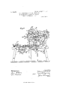
- the application of the cleaning substance and the removal thereof after the oil is absorbed are accomplished in a continuous operation and without intermission, thus performing in the most efficient manner that which was inefficiently accom plished by the use of the machines as heretofore, and this object we accomplish by the apparatus hereinafter more specifically described, reference being had to the accompa nying drawings, forming part hereof, in which v Figure 1 is a side elevation of the lefthand side of the machine.
- Fig. 2 is the same of the opposite or right-hand side of the machine.
- Fig. 3 is a plan view.
- Fig. 4 is alongitudinal section on the line 4 4 of Fig. 3.
- 1 is a base or frame, upon which the housing 2 is suitably,
- a shaft which is journaled in secured. bearings formed in the side of said housing, through which power is applied to the machine.
- One end of said shaft is provided with a clutch member a, which is adapted to engage a similar clutch member 4, connected to one of the belt-pulleys b for the purpose of making said pulleys rigid on said shafts 3, whereby ower maybe transmitted to said shaft 3.
- T e end of said shaft 3 opposite to that on which the belt-pulley is mounted is provided with a large spur-gear 5, which meshes with and transmits power to the small pinion 6, mounted on one end of the shaft 7, which is journaled in bearings c 0, formed in'the pillow-blocks secured to the top of said housing at each side thereof.
- the said chain passes over an idler 35 and the sprocket 36 on the shaft 37 for the purpose of transmitting motion to the conveyors 38, which operate over drums 39 40.
- Shaft 3 on the right-hand side of the machine adjacent to the belt-pulley b is provided with a small sprocket 41, on which a chain 42 operates to transmit motion to the shaft 43 and the roll 44, mounted thereon, through a sprocket-wheel 45 and over a similar sprocket-wheel on shaft 46 to operate the roll 48, mounted on said shaft 46.
- the said chain 42 then operates over an idler sprocketwheel 49, mounted on the spindle 12, the
- a crank-62 is mounted on the extreme outer end of shaft 46, and a link 63 extends from said crank and is connected to the rod 64, which is supported in bearings e, whereby when said crank is rotated by said shaft the said rod is caused to reciprocate longitudinally of the machine, and by means of the pawls 65 and 66, which are carried by said rod and which, respectively, engage the ratchet-wheels 67 and 68, operate the agitators 69 and 70, which are mounted on the shafts 71 and 72, respectively, on the ends of which the said ratchet-wheels are mounted.
- the extreme outer end of the shaft 46 on the right-hand side of the machine has mounted thereon the small beltpulley 73, over'which operates the belt or chain 74 for the purpose of transmitting motion to the large wheel 75, which is mounted on the shaft 76, secured in the frame below the top thereof.
- the said wheel 75 is provided with or carries two projecting pins or knockers 77 and 78, which during the revolution of said wheel contact with, respectively, the long projection or finger 79, fixed in the shaft 80, and the downwardly-projecting finger 81, which is adjustably secured to the rod 82 for the purpose hereinafter specified.
- the end of said rod 82 nearest said wheel 75 is loosely secured in the bearing f, and the opposite end is ivotally connected to one end of the arm or ever 83, the opposite end of which -is fixed upon a shaft 84, mounted in the bracket 85, which is bolted or otherwise secured to the rear end or leg of the frame.
- One end of the rods 86 is likewise secured upon the shaft .84, the opposite end thereof being ivotally connected to the upper end of a link 87, the lower end of which is pivotally connected to the upper end of the plate or sheet feeder 88.
- a sheet-supporter 89 which receives the sheets as they leave the conveyer,
- the agitators 69 and 70 are located in a compartment or box A, which extends transversely of the machine, near the sides thereof, in which bran or other suitable material is placed for cleaning the sheets or plates in their passage therethrough, the bottom of said box having an opening B, through which the sheets pass vertically from the rolls 34 and 48.
- the sheets then pass throu h the rolls 33 and 44 to and through the small rolls 60 61, and finally through the rolls 24 25, to the inclined support 96, the sheets being fed upon said support by the action of the rolls being directed thereon by the guide 97.
- the lower edge of the sheet clears the rolls it is carried forward to the inclined guide 98 by the action of the roll 25, assisted by gravity, and down the said inclined guide to the rolls 53 and 54, and finally through the rolls.
- 23 and 26 being thorou hly cleaned and burnished by the action of t e different sets of rolls.
- the clutch b is controlled by the lever 99, which is connected therewith by means of the rods 100 101.
- the box A is filled with bran or other suitable material to clean the plates almost to the upper edge of the rolls 33 44.
- the rolls 34 48 are preferably formed of a series of paper disks.
- two sets of large rolls 33 44 and 23 26 and 24 25 are formed of paper and flannel, the paper being formed upon the shaft about two thirds the diameter thereof.
- the two sets of small rolls 53 54 and 60 61 are composed of linen or muslin.
- One of the principal features of novelty of our invention resides in the series of horizontally-disposed rolls arcompressing the same thereon prior to the cleaning operation, as in machines heret0- after the sheet has been thrown at greater speed than those in alinement therewith and the set 23 26 at greater speed than the set of small rolls adjacent thereto.
- the sheets are placed one at a time upon the receiver, the lower edge thereof resting in the hooked lower end of the receiver, and are held in vertical position until the knocker 77 on the wheel 75 engages the finger 79, which is fixed on the shaft on which the receiver is mounted.
- the movement of the finger outward and upward rotates said shaft and throws the receiver downward and inward, thereby depositing the sheet on the conveyers, which carry it toward the inclined supporter 89, and from thence it passes by gravity to the sheetfeeder, which is vertically disposed and in alinement with the pass of the rolls through which it subsequently passes.
- a movable conveyer In a machine for cleaning tin and terne sheets or plates, the combination of a movable conveyer, a sheet-receiver, means to transfer the sheet from said receiver to the movable conveyer, a sheet-feeder, and means to transfer the sheets successively from said movable conveyer to said feeder.
- a sheet-conveyer means to operate said conveyer from said power-shaft, a vertically-disposed sheet-feeder in alinement with the pass of one of said sets of rolls, a wheel carrying two knockers and rotated by power from one of said rolls, a rod carrying an adjustable finger, the said rod being located with reference to said Wheel so as to enable the knockers thereon to contact with said finger, levers connecting said rod and said sheet-feeder, a normally vertically disposed sheet-holder mounted on a shaft, a counterweighted arm mounted on said shaft, a finger mounted on said shaft and adapted to engage the knockers on said wheel, whereby the rotation of said wheel successively elevates the feeder and depresses the sheet-holder.
- a reciprocating sheet-feeder of feeding-rolls adapted to take the sheet from the reciprocating feeder, cleaning-rolls adapted to receive the sheet fed by the feeding-rolls, and means for subjecting the sheet to a cleaning material as it is passing from the feeding-rolls to the cleaning-rolls.
- the combination with a receptacle for containing the cleaning material of a single set of rolls adapted to feed the sheets into the cleaning material, and cleaning-rolls positioned to receive the sheet as it emerges from the cleaning material.
- a machine for cleaning tin or terne plates or sheets the combination with a receptacle for containing the cleaning material, of a single set of rolls adapted to feed the sheets into the cleaning material, cleaningrolls positioned to receive the sheet as it emerges from the cleaning material, and an automatic feeder for delivering the sheets to the feeding-rolls.
- a reciprocating feeder for successively delivering the sheets to the cleaning means, an inclined sheet-supporter for feeding the sheets to the sheet-feeder, a conveyer for delivering the sheets to the inclined sheet-supporter, a tilting sheet-receiver for initially receiving the sheets and adapted to deliver the sheets to the conveyer, and mechanism adapted to automatically operate the devices aforesaid, whereby the sheets are successively fed from the sheet-receiver to the conveyer, thence to the sheet-supporter,
Landscapes
- Engineering & Computer Science (AREA)
- Mechanical Engineering (AREA)
- Cleaning In General (AREA)
Description
No. 821,908. PATBNTED MAY 29, 1906. W..O. WEIOHSBL & U. G. KNUPPENBURG.
MACHINE FOR CLEANING TIN PLATES.
APPLICATION FILED SEPT. 9. 1904.
4 SHEETS-SHEET 1.
witnesses;
musmom W66 Joe?" 44. law/Aim,
Ait'y:
munsw a alumm c0. Pmw-umocnwnzns. wunmcwn, n. cy
No. 821,908- PATENTED MAY 29, 1906.
W. 0. WBIGHSEL & U. G. KNUPPENBURG. MACHINE FOB CLEANING TIN PLATES.
APPLICATION FILED SBPT.9,1904. v
4 SHEETS-SHEET 2.
7mm 2 m Sses Wflwvw C i &4 6 i MQM W Ma No. 821,908. PATENTBD MAY 29, 1906. W. C. WEIGHSEL & U. G. KNUPPENBURG.
, MACHINE FOR CLEANING TIN PLATES.
APPLICATION FILED SEPT. 9.1904.
4 SHEETS-SHEET s.
mnnzw av GRAHAM 00,. PNOTO-UYHGGRAPNERS. WASNNGYON, n C.
No. 821,908; PATENTEDMAY 29, 1906.
W; 0. WEIOHSEL & U G. KNUPPENBURG.
MACHINE FOR CLEANING TIN PLATES.
APPLIOATION FILED SEPT.9,1904.
4 SHEETS-SHEET 4.
Q6522? it;
a mw f rvwu M wmw 1% nwwsw s emu-1m co PNOTO-LIYMUGRAPHERS. wAsums on. a. c.
UNITED STATES PATENT OFFICE.
WILLIAM GHARLES'WEIGHSEL AND ULYSSES GRANT KNUPPENBURG, OF
AVONMORE, PENNSYLVANIA.
MACHINE "FOR CLEANING TIN PLATES.
Specification of Letters Patent.
Patented May 29, 1906.
Application filed $eptember 9. 1904. Serial No, 223.882. i
BURG, citizens of the United States, residing at Avonmore, in the county of Westmoreland and State of Pennsylvania, have jointly invented a new and useful Improvement in Machines for Cleaning Tin Plates, of which improvement the following is a specification.
Our invention relates to improvements in mechanism or a paratus for cleaning tin or terne plates or s eets.
In the manufacture of tin or terne plates or sheets it is the usual practice to subject. the sheets immediately after tinning to an oil-bath to give luster thereto and then to remove or absorb the oil by passing the sheets through bran or similar substances. It is desirable that the shortest practicable time elapse while the sheets are passing from the oil-bath to the body of bran and that as' few transferring devices, such as feed-ro]ls,'
as possible act thereon to effect such passage, as the oil quickly becomes cold and in consequence difficult to remove, while the action of feed-rolls tends to blur or dull the finish of the sheets. Y p
In the machines heretofore employedfor cleaning plates or sheets the manner of ap-:
plying the bran or similar cleaning substance was unreliable, .failing to a very considerable extent to absorb and remove the oil from the surface of the sheets and tending to cake the oil on the plates and dull their finish.
The object of our invention is to produce a machine by the use of which the cleaning substance is effectively applied while the plate is hot from the tinning-bath and the oil on the plate is in a liquid state and is easily removable. The application of the cleaning substance and the removal thereof after the oil is absorbed are accomplished in a continuous operation and without intermission, thus performing in the most efficient manner that which was inefficiently accom plished by the use of the machines as heretofore, and this object we accomplish by the apparatus hereinafter more specifically described, reference being had to the accompa nying drawings, forming part hereof, in which v Figure 1 is a side elevation of the lefthand side of the machine.
Fig. 2 is the same of the opposite or right-hand side of the machine. Fig. 3 is a plan view. Fig. 4 is alongitudinal section on the line 4 4 of Fig. 3.
Referring to said drawings, 1 is a base or frame, upon which the housing 2 is suitably,
3 is a shaft which is journaled in secured. bearings formed in the side of said housing, through which power is applied to the machine. One end of said shaft is provided with a clutch member a, which is adapted to engage a similar clutch member 4, connected to one of the belt-pulleys b for the purpose of making said pulleys rigid on said shafts 3, whereby ower maybe transmitted to said shaft 3. T e end of said shaft 3 opposite to that on which the belt-pulley is mounted is provided with a large spur-gear 5, which meshes with and transmits power to the small pinion 6, mounted on one end of the shaft 7, which is journaled in bearings c 0, formed in'the pillow-blocks secured to the top of said housing at each side thereof. 8 is a sprocket-wheel mounted on shaft 7, through which motion is communicated to a small sprocket-wheel 9, mounted on the shaft 10, which is secured in the adjustable bearings d, formed in said housing, and to an idler sprocket-wheel 11, mounted on the 19 and 20 and to the sprocket 21, which is mounted on the shaft 22. The chains 13 and 16 transmit power from the large sprocket 8 to the shafts 10, 19,20, and 22 for the purpose of driving the rolls 23, 24, 25, and 26, mounted on said shafts, respectively, at auniform rate of speed.
27 is a small sprocket-wheel, which is mounted on shaft 3 adjacent to the large spur-wheel 5, over which the chain 28 operates to transmit power to the sprockets 29 30 for the purpose of rotating the shafts 31 and 32, on which, respectively, said sprockets are mounted, and to rotate the rolls 33 and 34 also on said shafts,
respectively. The said chain passes over an idler 35 and the sprocket 36 on the shaft 37 for the purpose of transmitting motion to the conveyors 38, which operate over drums 39 40. Shaft 3 on the right-hand side of the machine adjacent to the belt-pulley b is provided with a small sprocket 41, on which a chain 42 operates to transmit motion to the shaft 43 and the roll 44, mounted thereon, through a sprocket-wheel 45 and over a similar sprocket-wheel on shaft 46 to operate the roll 48, mounted on said shaft 46. The said chain 42 then operates over an idler sprocketwheel 49, mounted on the spindle 12, the
bearings of which are adjustably secured in I the housings 2 by means of the screw 50.
The said chain further operates ,over the sprocket 51, mounted on the end of the shaft 52 for the purpose of rotating'the roll 53, mounted on the shaft 55, being driven by friction from said last-mentioned roll. The said chain finally passes over the sprockets 56 and 57, which are mounted on the ends of shafts 58 and 59, respectively, for the purpose of rotating the rolls 60 and 61, mounted on said shafts, respectively. A crank-62 is mounted on the extreme outer end of shaft 46, and a link 63 extends from said crank and is connected to the rod 64, which is supported in bearings e, whereby when said crank is rotated by said shaft the said rod is caused to reciprocate longitudinally of the machine, and by means of the pawls 65 and 66, which are carried by said rod and which, respectively, engage the ratchet-wheels 67 and 68, operate the agitators 69 and 70, which are mounted on the shafts 71 and 72, respectively, on the ends of which the said ratchet-wheels are mounted. The extreme outer end of the shaft 46 on the right-hand side of the machine has mounted thereon the small beltpulley 73, over'which operates the belt or chain 74 for the purpose of transmitting motion to the large wheel 75, which is mounted on the shaft 76, secured in the frame below the top thereof. The said wheel 75 is provided with or carries two projecting pins or knockers 77 and 78, which during the revolution of said wheel contact with, respectively, the long projection or finger 79, fixed in the shaft 80, and the downwardly-projecting finger 81, which is adjustably secured to the rod 82 for the purpose hereinafter specified. The end of said rod 82 nearest said wheel 75 is loosely secured in the bearing f, and the opposite end is ivotally connected to one end of the arm or ever 83, the opposite end of which -is fixed upon a shaft 84, mounted in the bracket 85, which is bolted or otherwise secured to the rear end or leg of the frame. One end of the rods 86 is likewise secured upon the shaft .84, the opposite end thereof being ivotally connected to the upper end of a link 87, the lower end of which is pivotally connected to the upper end of the plate or sheet feeder 88. A sheet-supporter 89, which receives the sheets as they leave the conveyer,
is connected at its upper end to the rod 90, on which the counterweighted arm 91' is fixed, the counterweight 92 being secured upon said arm by the set-screw g and being adapted to be adjusted thereon to vary the fulcrum of said arm. A sheet-receiver 93 is fixed upon said shaft 80, the lower hooked end of which receives the lower edge of the sheet and maintains the same in a vertical position until thrown down, as herein after described. An
The agitators 69 and 70 are located in a compartment or box A, which extends transversely of the machine, near the sides thereof, in which bran or other suitable material is placed for cleaning the sheets or plates in their passage therethrough, the bottom of said box having an opening B, through which the sheets pass vertically from the rolls 34 and 48. The sheets then pass throu h the rolls 33 and 44 to and through the small rolls 60 61, and finally through the rolls 24 25, to the inclined support 96, the sheets being fed upon said support by the action of the rolls being directed thereon by the guide 97. Immediately the lower edge of the sheet clears the rolls it is carried forward to the inclined guide 98 by the action of the roll 25, assisted by gravity, and down the said inclined guide to the rolls 53 and 54, and finally through the rolls. 23 and 26, being thorou hly cleaned and burnished by the action of t e different sets of rolls. The clutch b is controlled by the lever 99, which is connected therewith by means of the rods 100 101.
. In operating the machine the box A is filled with bran or other suitable material to clean the plates almost to the upper edge of the rolls 33 44. The rolls 34 48 are preferably formed of a series of paper disks. The
two sets of large rolls 33 44 and 23 26 and 24 25 are formed of paper and flannel, the paper being formed upon the shaft about two thirds the diameter thereof. The two sets of small rolls 53 54 and 60 61 are composed of linen or muslin. One of the principal features of novelty of our invention resides in the series of horizontally-disposed rolls arcompressing the same thereon prior to the cleaning operation, as in machines heret0- after the sheet has been thrown at greater speed than those in alinement therewith and the set 23 26 at greater speed than the set of small rolls adjacent thereto. The sheets are placed one at a time upon the receiver, the lower edge thereof resting in the hooked lower end of the receiver, and are held in vertical position until the knocker 77 on the wheel 75 engages the finger 79, which is fixed on the shaft on which the receiver is mounted. The movement of the finger outward and upward rotates said shaft and throws the receiver downward and inward, thereby depositing the sheet on the conveyers, which carry it toward the inclined supporter 89, and from thence it passes by gravity to the sheetfeeder, which is vertically disposed and in alinement with the pass of the rolls through which it subsequently passes. Immediately upon the conveyer the wheel 75 in its further revolution brings the knocker 78 into contact with the finger 81 on the rod 82, moving the rod forward and through the levers 83 86, elevating the feeder, in which the sheet is then deposited sufficiently to enter said sheet between rolls 34 48, the action of which forces the sheet through the bran contained in the-compartment A, thoroughly cleansing the sheet of the oil. The lower edge of the sheet is still in the rolls 34 48 when the upper edge enters the pass between rolls 33 44, the function of which is to remove the bran and feed the sheet to the small rolls 61, the action of which more completely cleans the sheets, and from the fact that the rolls 24 25, located a short distance therefrom, rotate more rapidly than the rolls 6O 61 a burnishing operation is obtained. After the sheet is discharged from rolls 24 25 it isthrown upon the guide 96, and from there it is transferred by gravity and the action of the roll 25 onto the incline 98, and from thence through the two sets of rolls 52 53 and 23 26, when it is completely cleaned.
We claim as our invention and desire to secure by Letters Patent- 1'. In a machine for cleaning tin or terne plates or sheets, the combination of a conveyer, a vertically-disposed plate feeder, means to transfer the sheet from said conveyer to said feeder, a series of horizontallydisposed rolls in vertical alinement, and
means to elevate the sheet-feeder to enter the 6 5 sheet in the pass of the first set of rolls.
2. In a machine for cleaning tin and terne sheets or plates, the combination of a movable conveyer, a sheet-receiver, means to transfer the sheet from said receiver to the movable conveyer, a sheet-feeder, and means to transfer the sheets successively from said movable conveyer to said feeder.
3. In a tin-sheet-cleaning machine, the combination ofa power-shaft, a series of sets of rollsin vertical alinement, means connecting said power-shaft and said rolls whereby said rolls are driven in the same direction, a sheet-conveyer, means to operate said conveyer from said power-shaft, a vertically-disposed sheet-feeder in alinement with the pass of one of said sets of rolls, a wheel carrying two knockers and rotated by power from one of said rolls, a rod carrying an adjustable finger, the said rod being located with reference to said Wheel so as to enable the knockers thereon to contact with said finger, levers connecting said rod and said sheet-feeder, a normally vertically disposed sheet-holder mounted on a shaft, a counterweighted arm mounted on said shaft, a finger mounted on said shaft and adapted to engage the knockers on said wheel, whereby the rotation of said wheel successively elevates the feeder and depresses the sheet-holder.
4. In a machine for cleaning tin or terne plates or sheets, the combination with a reciprocating sheet-feeder, of cleaning-rolls adapted to receive the sheet, and means for subjecting the sheet to a cleaning material as it is passing from the reciprocating feeder to the cleaning-rolls.
5. In a machine for cleaning tin or terne plates or sheets, the combination with a reciprocating sheet-feeder, of feeding-rolls adapted to take the sheet from the reciprocating feeder, cleaning-rolls adapted to receive the sheet fed by the feeding-rolls, and means for subjecting the sheet to a cleaning material as it is passing from the feeding-rolls to the cleaning-rolls.
6. In a machine for cleaning tin or terne plates or sheets, the combination with a receptacle for containing the cleaning material, of a single set of rolls adapted to feed the sheets into the cleaning material, and cleaning-rolls positioned to receive the sheet as it emerges from the cleaning material.
7. In a machine for cleaning tin or terne plates or sheets, the combination with a receptacle for containing the cleaning material, of a single set of rolls adapted to feed the sheets into the cleaning material, cleaningrolls positioned to receive the sheet as it emerges from the cleaning material, and an automatic feeder for delivering the sheets to the feeding-rolls.
8. In a machine for cleaning tin or terne plates or sheets, the combination with cleaning means, of a reciprocating feeder for successively delivering the sheets to the cleaning means, an inclined sheet-supporter for feeding the sheets to the sheet-feeder, a conveyer for delivering the sheets to the inclined sheet-supporter, a tilting sheet-receiver for initially receiving the sheets and adapted to deliver the sheets to the conveyer, and mechanism adapted to automatically operate the devices aforesaid, whereby the sheets are successively fed from the sheet-receiver to the conveyer, thence to the sheet-supporter,
and finally from the sheet-feeder to the clean- WILLIAM CHARLES WEICHSEL. ULYSSES GRANT KNUPPENBURG.
In presence of J. A. WAGLE, A. W. SMITH.
Priority Applications (1)
| Application Number | Priority Date | Filing Date | Title |
|---|---|---|---|
| US22388204A US821908A (en) | 1904-09-09 | 1904-09-09 | Machine for cleaning tin plates. |
Applications Claiming Priority (1)
| Application Number | Priority Date | Filing Date | Title |
|---|---|---|---|
| US22388204A US821908A (en) | 1904-09-09 | 1904-09-09 | Machine for cleaning tin plates. |
Publications (1)
| Publication Number | Publication Date |
|---|---|
| US821908A true US821908A (en) | 1906-05-29 |
Family
ID=2890388
Family Applications (1)
| Application Number | Title | Priority Date | Filing Date |
|---|---|---|---|
| US22388204A Expired - Lifetime US821908A (en) | 1904-09-09 | 1904-09-09 | Machine for cleaning tin plates. |
Country Status (1)
| Country | Link |
|---|---|
| US (1) | US821908A (en) |
-
1904
- 1904-09-09 US US22388204A patent/US821908A/en not_active Expired - Lifetime
Similar Documents
| Publication | Publication Date | Title |
|---|---|---|
| US807162A (en) | Apparatus for processing meats, &c. | |
| US821908A (en) | Machine for cleaning tin plates. | |
| US1801572A (en) | Machine for applying shredded material to confection-coated wafers and the like | |
| US1415258A (en) | Can-polishing machine | |
| US1331460A (en) | Coating-machine | |
| US709382A (en) | Sweetmeat-machine. | |
| US1309401A (en) | Beah-sortistg machine | |
| US1350549A (en) | Nut-blanching machine | |
| US1192156A (en) | Cutting and rolling machine for plastic materials. | |
| US883458A (en) | Galvanizing apparatus. | |
| US732970A (en) | Can-soldering machine. | |
| US844049A (en) | Machine for sizing tobacco-leaves. | |
| US634325A (en) | Machine for filling hides or skins. | |
| US334343A (en) | Cider-machine | |
| US681255A (en) | Apparatus for manufacturing tin-plate. | |
| US756786A (en) | Bronzing-machine. | |
| US1484766A (en) | Machine for cleaning book covers and the like | |
| US1005764A (en) | Mechanism for curing and preparing grasses for packing-pads and upholstery purposes. | |
| US934057A (en) | Machine for making mica plates and the like. | |
| US645394A (en) | Wine-press. | |
| US260494A (en) | meyer | |
| US1937421A (en) | Ironing machine | |
| US1387884A (en) | Apparatus for cleaning book-covers and the like | |
| US1199682A (en) | Manufacture of composition board. | |
| US544127A (en) | Bottle or can labeling machine |