US8215284B2 - Micro-pilot injection ignition type gas engine - Google Patents
Micro-pilot injection ignition type gas engine Download PDFInfo
- Publication number
- US8215284B2 US8215284B2 US12/450,452 US45045208A US8215284B2 US 8215284 B2 US8215284 B2 US 8215284B2 US 45045208 A US45045208 A US 45045208A US 8215284 B2 US8215284 B2 US 8215284B2
- Authority
- US
- United States
- Prior art keywords
- gas
- engine
- cylinder
- fuel
- firing
- Prior art date
- Legal status (The legal status is an assumption and is not a legal conclusion. Google has not performed a legal analysis and makes no representation as to the accuracy of the status listed.)
- Active, expires
Links
- 238000002347 injection Methods 0.000 title claims abstract description 15
- 239000007924 injection Substances 0.000 title claims abstract description 15
- 238000010304 firing Methods 0.000 claims abstract description 115
- 239000007789 gas Substances 0.000 claims abstract description 88
- 238000002485 combustion reaction Methods 0.000 claims abstract description 66
- 239000002737 fuel gas Substances 0.000 claims abstract description 61
- 238000009826 distribution Methods 0.000 claims abstract description 54
- 238000003745 diagnosis Methods 0.000 claims abstract description 27
- 239000000203 mixture Substances 0.000 claims description 21
- 239000000295 fuel oil Substances 0.000 claims description 20
- 239000000567 combustion gas Substances 0.000 claims description 6
- 230000004044 response Effects 0.000 claims description 3
- 239000000446 fuel Substances 0.000 abstract description 23
- 230000010349 pulsation Effects 0.000 description 10
- 238000000034 method Methods 0.000 description 7
- 238000005516 engineering process Methods 0.000 description 6
- 238000010586 diagram Methods 0.000 description 4
- 230000009471 action Effects 0.000 description 2
- 230000006835 compression Effects 0.000 description 2
- 238000007906 compression Methods 0.000 description 2
- 230000007246 mechanism Effects 0.000 description 2
- 230000002159 abnormal effect Effects 0.000 description 1
- 230000001276 controlling effect Effects 0.000 description 1
- 230000002708 enhancing effect Effects 0.000 description 1
- 230000006872 improvement Effects 0.000 description 1
- 239000000463 material Substances 0.000 description 1
- 230000008569 process Effects 0.000 description 1
- 238000005086 pumping Methods 0.000 description 1
- 230000009467 reduction Effects 0.000 description 1
- 230000001105 regulatory effect Effects 0.000 description 1
- 230000007704 transition Effects 0.000 description 1
- 238000011144 upstream manufacturing Methods 0.000 description 1
Images


Classifications
-
- F—MECHANICAL ENGINEERING; LIGHTING; HEATING; WEAPONS; BLASTING
- F02—COMBUSTION ENGINES; HOT-GAS OR COMBUSTION-PRODUCT ENGINE PLANTS
- F02B—INTERNAL-COMBUSTION PISTON ENGINES; COMBUSTION ENGINES IN GENERAL
- F02B19/00—Engines characterised by precombustion chambers
- F02B19/10—Engines characterised by precombustion chambers with fuel introduced partly into pre-combustion chamber, and partly into cylinder
-
- F—MECHANICAL ENGINEERING; LIGHTING; HEATING; WEAPONS; BLASTING
- F02—COMBUSTION ENGINES; HOT-GAS OR COMBUSTION-PRODUCT ENGINE PLANTS
- F02D—CONTROLLING COMBUSTION ENGINES
- F02D41/00—Electrical control of supply of combustible mixture or its constituents
- F02D41/02—Circuit arrangements for generating control signals
- F02D41/04—Introducing corrections for particular operating conditions
- F02D41/06—Introducing corrections for particular operating conditions for engine starting or warming up
-
- F—MECHANICAL ENGINEERING; LIGHTING; HEATING; WEAPONS; BLASTING
- F02—COMBUSTION ENGINES; HOT-GAS OR COMBUSTION-PRODUCT ENGINE PLANTS
- F02B—INTERNAL-COMBUSTION PISTON ENGINES; COMBUSTION ENGINES IN GENERAL
- F02B77/00—Component parts, details or accessories, not otherwise provided for
- F02B77/08—Safety, indicating, or supervising devices
- F02B77/085—Safety, indicating, or supervising devices with sensors measuring combustion processes, e.g. knocking, pressure, ionization, combustion flame
-
- F—MECHANICAL ENGINEERING; LIGHTING; HEATING; WEAPONS; BLASTING
- F02—COMBUSTION ENGINES; HOT-GAS OR COMBUSTION-PRODUCT ENGINE PLANTS
- F02D—CONTROLLING COMBUSTION ENGINES
- F02D19/00—Controlling engines characterised by their use of non-liquid fuels, pluralities of fuels, or non-fuel substances added to the combustible mixtures
- F02D19/02—Controlling engines characterised by their use of non-liquid fuels, pluralities of fuels, or non-fuel substances added to the combustible mixtures peculiar to engines working with gaseous fuels
-
- F—MECHANICAL ENGINEERING; LIGHTING; HEATING; WEAPONS; BLASTING
- F02—COMBUSTION ENGINES; HOT-GAS OR COMBUSTION-PRODUCT ENGINE PLANTS
- F02D—CONTROLLING COMBUSTION ENGINES
- F02D19/00—Controlling engines characterised by their use of non-liquid fuels, pluralities of fuels, or non-fuel substances added to the combustible mixtures
- F02D19/06—Controlling engines characterised by their use of non-liquid fuels, pluralities of fuels, or non-fuel substances added to the combustible mixtures peculiar to engines working with pluralities of fuels, e.g. alternatively with light and heavy fuel oil, other than engines indifferent to the fuel consumed
- F02D19/0602—Control of components of the fuel supply system
- F02D19/0607—Control of components of the fuel supply system to adjust the fuel mass or volume flow
- F02D19/061—Control of components of the fuel supply system to adjust the fuel mass or volume flow by controlling fuel injectors
-
- F—MECHANICAL ENGINEERING; LIGHTING; HEATING; WEAPONS; BLASTING
- F02—COMBUSTION ENGINES; HOT-GAS OR COMBUSTION-PRODUCT ENGINE PLANTS
- F02D—CONTROLLING COMBUSTION ENGINES
- F02D19/00—Controlling engines characterised by their use of non-liquid fuels, pluralities of fuels, or non-fuel substances added to the combustible mixtures
- F02D19/06—Controlling engines characterised by their use of non-liquid fuels, pluralities of fuels, or non-fuel substances added to the combustible mixtures peculiar to engines working with pluralities of fuels, e.g. alternatively with light and heavy fuel oil, other than engines indifferent to the fuel consumed
- F02D19/0623—Failure diagnosis or prevention; Safety measures; Testing
-
- F—MECHANICAL ENGINEERING; LIGHTING; HEATING; WEAPONS; BLASTING
- F02—COMBUSTION ENGINES; HOT-GAS OR COMBUSTION-PRODUCT ENGINE PLANTS
- F02D—CONTROLLING COMBUSTION ENGINES
- F02D19/00—Controlling engines characterised by their use of non-liquid fuels, pluralities of fuels, or non-fuel substances added to the combustible mixtures
- F02D19/06—Controlling engines characterised by their use of non-liquid fuels, pluralities of fuels, or non-fuel substances added to the combustible mixtures peculiar to engines working with pluralities of fuels, e.g. alternatively with light and heavy fuel oil, other than engines indifferent to the fuel consumed
- F02D19/0626—Measuring or estimating parameters related to the fuel supply system
- F02D19/0628—Determining the fuel pressure, temperature or flow, the fuel tank fill level or a valve position
- F02D19/0631—Determining the fuel pressure, temperature or flow, the fuel tank fill level or a valve position by estimation, i.e. without using direct measurements of a corresponding sensor
-
- F—MECHANICAL ENGINEERING; LIGHTING; HEATING; WEAPONS; BLASTING
- F02—COMBUSTION ENGINES; HOT-GAS OR COMBUSTION-PRODUCT ENGINE PLANTS
- F02D—CONTROLLING COMBUSTION ENGINES
- F02D19/00—Controlling engines characterised by their use of non-liquid fuels, pluralities of fuels, or non-fuel substances added to the combustible mixtures
- F02D19/06—Controlling engines characterised by their use of non-liquid fuels, pluralities of fuels, or non-fuel substances added to the combustible mixtures peculiar to engines working with pluralities of fuels, e.g. alternatively with light and heavy fuel oil, other than engines indifferent to the fuel consumed
- F02D19/08—Controlling engines characterised by their use of non-liquid fuels, pluralities of fuels, or non-fuel substances added to the combustible mixtures peculiar to engines working with pluralities of fuels, e.g. alternatively with light and heavy fuel oil, other than engines indifferent to the fuel consumed simultaneously using pluralities of fuels
- F02D19/10—Controlling engines characterised by their use of non-liquid fuels, pluralities of fuels, or non-fuel substances added to the combustible mixtures peculiar to engines working with pluralities of fuels, e.g. alternatively with light and heavy fuel oil, other than engines indifferent to the fuel consumed simultaneously using pluralities of fuels peculiar to compression-ignition engines in which the main fuel is gaseous
-
- F—MECHANICAL ENGINEERING; LIGHTING; HEATING; WEAPONS; BLASTING
- F02—COMBUSTION ENGINES; HOT-GAS OR COMBUSTION-PRODUCT ENGINE PLANTS
- F02D—CONTROLLING COMBUSTION ENGINES
- F02D35/00—Controlling engines, dependent on conditions exterior or interior to engines, not otherwise provided for
- F02D35/02—Controlling engines, dependent on conditions exterior or interior to engines, not otherwise provided for on interior conditions
- F02D35/023—Controlling engines, dependent on conditions exterior or interior to engines, not otherwise provided for on interior conditions by determining the cylinder pressure
-
- F—MECHANICAL ENGINEERING; LIGHTING; HEATING; WEAPONS; BLASTING
- F02—COMBUSTION ENGINES; HOT-GAS OR COMBUSTION-PRODUCT ENGINE PLANTS
- F02D—CONTROLLING COMBUSTION ENGINES
- F02D41/00—Electrical control of supply of combustible mixture or its constituents
- F02D41/0025—Controlling engines characterised by use of non-liquid fuels, pluralities of fuels, or non-fuel substances added to the combustible mixtures
- F02D41/0027—Controlling engines characterised by use of non-liquid fuels, pluralities of fuels, or non-fuel substances added to the combustible mixtures the fuel being gaseous
-
- F—MECHANICAL ENGINEERING; LIGHTING; HEATING; WEAPONS; BLASTING
- F02—COMBUSTION ENGINES; HOT-GAS OR COMBUSTION-PRODUCT ENGINE PLANTS
- F02D—CONTROLLING COMBUSTION ENGINES
- F02D41/00—Electrical control of supply of combustible mixture or its constituents
- F02D41/008—Controlling each cylinder individually
- F02D41/0087—Selective cylinder activation, i.e. partial cylinder operation
-
- F—MECHANICAL ENGINEERING; LIGHTING; HEATING; WEAPONS; BLASTING
- F02—COMBUSTION ENGINES; HOT-GAS OR COMBUSTION-PRODUCT ENGINE PLANTS
- F02D—CONTROLLING COMBUSTION ENGINES
- F02D41/00—Electrical control of supply of combustible mixture or its constituents
- F02D41/02—Circuit arrangements for generating control signals
- F02D41/04—Introducing corrections for particular operating conditions
-
- F—MECHANICAL ENGINEERING; LIGHTING; HEATING; WEAPONS; BLASTING
- F02—COMBUSTION ENGINES; HOT-GAS OR COMBUSTION-PRODUCT ENGINE PLANTS
- F02D—CONTROLLING COMBUSTION ENGINES
- F02D41/00—Electrical control of supply of combustible mixture or its constituents
- F02D41/02—Circuit arrangements for generating control signals
- F02D41/14—Introducing closed-loop corrections
- F02D41/1438—Introducing closed-loop corrections using means for determining characteristics of the combustion gases; Sensors therefor
- F02D41/1444—Introducing closed-loop corrections using means for determining characteristics of the combustion gases; Sensors therefor characterised by the characteristics of the combustion gases
- F02D41/1454—Introducing closed-loop corrections using means for determining characteristics of the combustion gases; Sensors therefor characterised by the characteristics of the combustion gases the characteristics being an oxygen content or concentration or the air-fuel ratio
-
- F—MECHANICAL ENGINEERING; LIGHTING; HEATING; WEAPONS; BLASTING
- F02—COMBUSTION ENGINES; HOT-GAS OR COMBUSTION-PRODUCT ENGINE PLANTS
- F02D—CONTROLLING COMBUSTION ENGINES
- F02D41/00—Electrical control of supply of combustible mixture or its constituents
- F02D41/02—Circuit arrangements for generating control signals
- F02D41/14—Introducing closed-loop corrections
- F02D41/1438—Introducing closed-loop corrections using means for determining characteristics of the combustion gases; Sensors therefor
- F02D41/1473—Introducing closed-loop corrections using means for determining characteristics of the combustion gases; Sensors therefor characterised by the regulation method
- F02D41/1475—Regulating the air fuel ratio at a value other than stoichiometry
-
- F—MECHANICAL ENGINEERING; LIGHTING; HEATING; WEAPONS; BLASTING
- F02—COMBUSTION ENGINES; HOT-GAS OR COMBUSTION-PRODUCT ENGINE PLANTS
- F02D—CONTROLLING COMBUSTION ENGINES
- F02D41/00—Electrical control of supply of combustible mixture or its constituents
- F02D41/30—Controlling fuel injection
- F02D41/3011—Controlling fuel injection according to or using specific or several modes of combustion
- F02D41/3017—Controlling fuel injection according to or using specific or several modes of combustion characterised by the mode(s) being used
- F02D41/3035—Controlling fuel injection according to or using specific or several modes of combustion characterised by the mode(s) being used a mode being the premixed charge compression-ignition mode
- F02D41/3041—Controlling fuel injection according to or using specific or several modes of combustion characterised by the mode(s) being used a mode being the premixed charge compression-ignition mode with means for triggering compression ignition, e.g. spark plug
- F02D41/3047—Controlling fuel injection according to or using specific or several modes of combustion characterised by the mode(s) being used a mode being the premixed charge compression-ignition mode with means for triggering compression ignition, e.g. spark plug said means being a secondary injection of fuel
-
- F—MECHANICAL ENGINEERING; LIGHTING; HEATING; WEAPONS; BLASTING
- F02—COMBUSTION ENGINES; HOT-GAS OR COMBUSTION-PRODUCT ENGINE PLANTS
- F02M—SUPPLYING COMBUSTION ENGINES IN GENERAL WITH COMBUSTIBLE MIXTURES OR CONSTITUENTS THEREOF
- F02M21/00—Apparatus for supplying engines with non-liquid fuels, e.g. gaseous fuels stored in liquid form
- F02M21/02—Apparatus for supplying engines with non-liquid fuels, e.g. gaseous fuels stored in liquid form for gaseous fuels
-
- Y—GENERAL TAGGING OF NEW TECHNOLOGICAL DEVELOPMENTS; GENERAL TAGGING OF CROSS-SECTIONAL TECHNOLOGIES SPANNING OVER SEVERAL SECTIONS OF THE IPC; TECHNICAL SUBJECTS COVERED BY FORMER USPC CROSS-REFERENCE ART COLLECTIONS [XRACs] AND DIGESTS
- Y02—TECHNOLOGIES OR APPLICATIONS FOR MITIGATION OR ADAPTATION AGAINST CLIMATE CHANGE
- Y02T—CLIMATE CHANGE MITIGATION TECHNOLOGIES RELATED TO TRANSPORTATION
- Y02T10/00—Road transport of goods or passengers
- Y02T10/10—Internal combustion engine [ICE] based vehicles
- Y02T10/30—Use of alternative fuels, e.g. biofuels
Definitions
- the present application relates to a micro-pilot injection ignition type gas engine and an air fuel ratio control method thereof.
- the gas engine of the mentioned type inhales pre-mixed air fuel mixture into each cylinder, namely, into a main chamber, and initiates combustion of the mixture inside the main chamber with at least one pilot flame that jets out from a pre-chamber through at least one nozzle hole made in a pre-chamber housing, as an ignition-source for the mixture inside the main chamber; whereby the pilot flame jet is induced by means of combustion of an amount of micro-pilot fuel-oil that is injected through a pilot fuel injector as well as by means of combustion of a part of the air fuel mixture inhaled inside the pre-chamber from the main chamber through at least one nozzle hole.
- this application relates to an air fuel ratio control device that performs an open-close control as to a gas valve for each cylinder.
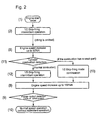
- FIG. 5 shows an example of a flow-chart diagram as to a starting method of a gas engine with a micro-pilot ignition system, according to a conventional technology.
- Step 1 a start order is transmitted to the engine; then, the engine is started with a 1 ⁇ 2 skip-firing intermittent operation (Step 2 ).
- Step 2 a 1 ⁇ 2 skip-firing intermittent operation
- each cylinder alternates a cycle with firing and a cycle without firing; that is, each cylinder repeats a cycle with combustion and a cycle without combustion alternately;
- Numerals 0 and 1 in the table of FIG. 3-1 correspond to the cycle without firing and the cycle with firing, respectively.
- each cylinder repeats a cluster of every five consecutive cycles with a non-firing cycle and four consecutive firing cycles as shown in the table of FIG. 3-2 ; thereby, Numerals 0 and 1 also correspond to the cycle without firing and the cycle with firing, respectively.
- 1 ⁇ 2 skip-fring intermittent operation or 1 ⁇ 5 skip-firing intermittent operation there can be another type of intermittent operation mode, such as a n/m skip-firing intermittent operation during which n non-firing cycles (skipped cycles) exist within m consecutive cycles.
- a n/m skip-firing intermittent operation during which n non-firing cycles (skipped cycles) exist within m consecutive cycles.
- Various kinds of intermittent operations are collectively cited with a term “skip mode” or “skip-firing mode” in this specification.
- the terms 1 ⁇ 2 skip-firing intermittent operation and 1 ⁇ 5 skip-firing intermittent operation in the above description are generalized, for example, with terms “a first skip mode” and “a second skip mode” respectively.
- n is equal to 1
- a 1/m skip-firing intermittent operation or a 1/m skip-firing mode can be defined; whereby, a non-firing cycle is placed between m ⁇ 1 consecutive firing cycles and m ⁇ 1 consecutive firing cycles; thereby, a ratio of valve-open-frequency to valve-closed-frequency increases, as the number m increases.
- this ratio is called a valve opening-ratio.
- m consecutive engine cycles are often called a cluster of cycles in this specification.
- the speed of the engine is increased (Step 3 ) to an 80% speed (80% N), that is, a prescribed idling speed of a rated speed N, while the 1 ⁇ 2 skip-firing intermittent operation is performed; at this stage, a timer is activated so that the engine continues the 80% N idling for three minutes (Step 4 and Step 5 ); then, the engine speed is increased to a 90% speed (90% N) of the speed N (Step 6 ); further, the 1 ⁇ 2 skip-firing intermittent operation is shifted to the 1 ⁇ 5 skip-firing intermittent operation (Step 7 ), namely, fuel supply frequency is increased as a state of one firing-skip cycle during two consecutive cycles is shifted to a state of one firing-skip during five consecutive cycles; then (Step 8 ), the engine speed is increased to 100% of the rated speed N (100% N).
- Step 9 when 10% load of the rated engine-load is detected (Step 9 ) during the speed of 100% N, the engine is put under normal speed operation without a skip-firing mode.
- a patent reference JP1997-14057 discloses a fuel supply device for starting a gas engine, the engine comprising:
- each cylinder a first fuel passage toward each main combustion chamber (each cylinder);
- fuel-gas and air are premixed and supplied to each main combustion chamber; further, in micro-pilot injection ignition type gas engines, at least one flame jet produced by the mentioned micro-pilot ignition system ignites the premixed air fuel mixture in the main chamber, and a lean-burn is performed; therefore, in the conventional gas engines of the type, engine speed fluctuations with unstable behavior are prone to occur, while the engine is in its starting process.
- a prerequisite to secure an ignition performance and a starting performance as to the four-stroke cycle gas engines is to bring the air fuel ratio of the air fuel mixture in the main chamber close to a stoichiometric mixture ratio as to the fuel-gas being used; however, when the engine is started and the speed is low, the fuel-gas supply rate is low, while the air supply rate is large because of relatively ample piston pumping work; thus, the air fuel ratio during starting the engine is too lean and is in fact considerably below the stoichiometric ratio.
- a conventional gas engine of a micro-pilot injection ignition type controls air fuel ratios in starting by means of enhancing fuel-gas flow rates, i.e. fuel-gas supply pressure pulsation through, while the 1 ⁇ 2 skip-firing intermittent operation and the 1 ⁇ 5 skip-firing intermittent operation are incorporated according to FIG. 5 .
- the 1 ⁇ 2 skip-firing intermittent operation and the 1 ⁇ 5 skip-firing intermittent operation are incorporated according to FIG. 5 , while 3 minutes idling operation is placed on a part way in the starting steps.
- the conventional manner according to FIG. 5 is not sufficiently useful to reduce the idling time span although the time reduction is desired.
- the present invention is aiming at providing a micro-pilot injection ignition type gas engine, whereby an air fuel ratio control in starting the engine is executed with enhanced precision, by means of introducing skip-firing intermittent operations the operations which reflect the engine operation conditions, while an idling time span in the starting steps can be shortened or omitted.
- a gas valve that delivers and cuts fuel-gas at a position in front of each cylinder, so as to arbitrarily control a throat area as well as an opening/closing time span of the gas valve;
- an engine speed detecting unit to detect the engine speed
- a cylinder pressure sensor provided at each cylinder so as to continually measure pressure levels as to each cylinder
- a combustion diagnosis unit to monitor the pressure levels so that the diagnosis unit analyzes an engine combustion state through a cylinder pressure distribution along elapsed time, the distribution as to each cylinder being formed in the diagnosis unit;
- an opening-closing control unit as to the gas valve, so as to control an intermittent opening/closing of the gas valve in response to the engine speed and the pressure distribution;
- the intermittent opening/closing of the gas-valve brings into operation at least one skip-firing mode that brings an enhanced fuel-supply pressure-pulsation with which an increased amount of fuel-gas is supplied per one engine cycle with firing so that the air fuel-gas ratio of each cylinder reaches a prescribed target value.
- the opening-closing control unit as to the gas valve makes the gas valve for each cylinder open and close, intermittently per each cylinder in turn according to a firing sequence of the engine, so that air fuel-gas ratio reaches the prescribed target value, with the skip-firing mode, and with a series of time spans as to the variable valve-opening-time span of the gas valve, the time spans being changed step by step.
- the opening-closing control unit preferably makes the gas valve for each cylinder open and close according to the skip-firing mode so that the air fuel-gas ratio reaches a prescribed value; further, the opening-time span of the gas valve is changed step by step during the engine starting.
- the opening-closing control unit makes the gas valve for each cylinder open and close with: a first skip-firing mode of a lower valve-opening-ratio in the case when the cylinder pressure distribution along elapsed time, as analyzed by the combustion diagnosis unit, corresponds to a prescribed target distribution, whereas the opening-closing control unit makes the gas valve open and close with a second skip-firing mode of a higher valve-opening-ratio in the case when the cylinder pressure distribution along elapsed time does not reach the prescribed target distribution.
- the engine includes:
- a cylinder pressure sensor provided at each cylinder so as to continually measure pressure levels as to each cylinder
- a combustion diagnosis unit to retrieve the pressure levels so that the diagnosis unit analyzes an engine combustion state through a cylinder pressure distribution along elapsed time, the distribution as to each cylinder being formed in the diagnosis unit;
- an opening-closing control unit as to the gas valve, so as to control an intermittent opening/closing of the gas valve in response to the engine speed and the pressure distribution;
- each cylinder performs and repeats engine cycles (a cluster of cycles) of a skip-firing mode by means of a corresponding skip-firing intermittent operation of the gas valve; hence, a relatively strong fuel-gas pressure pulsation is caused in a fuel-gas pipe that supplies fuel-gas to the gas valve, the pulsation bringing relatively large fuel-gas supply while the valve is being opened in comparison with usual cycle repetition without skipping; thus, the air fuel-gas ratio is enhanced in firing engine-cycles. Accordingly, a cluster of intermittent combustion cycles is repeated in each main combustion chamber; yet, the combustion during a firing cycle in each main chamber becomes stable and regular.
- the gas-valve opening and the gas-valve closing are repeated on a one-by-one basis, in turn; namely, in the main chamber, an engine cycle with firing and an engine cycle without firing are repeated in turn.
- a skip-firing mode for example, the already-mentioned number m (hereby the denominator 2 of the 1 ⁇ 2) of corresponding consecutive cycles as to an intermittent cycle-cluster is 2; whereby, a gas-valve opening and a gas-valve closing are repeated on a one-by-one basis, in turn.
- the mentioned 1/m skip-firing mode is concerned, the less the number m is the stronger the fuel-gas supply pressure pulsation is.
- a skip-firing mode namely, a skip-firing intermittent operation can be selected in consideration of the parameter m.
- the already-mentioned number m (hereby the denominator 2 of the 1 ⁇ 2) of corresponding consecutive cycles as to an intermittent cycle-cluster is 2; whereby, a gas-valve opening and a gas-valve closing are repeated on a one-by-one basis, in turn.
- a first skip-firing mode for example 1 ⁇ 2 skip-firing intermittent operation
- the gas valve as well as the engine is operated with a second skip-firing mode, for example 1 ⁇ 5 skip-firing intermittent operation, the second skip-firing mode being a higher valve-opening-ratio than the first mode.
- FIG. 1 shows a whole structure of a four-stroke cycle gas engine according to an embodiment of the present invention
- FIGS. 3-1 and 3 - 2 show a starting action allocation table (i.e., a starting skip-firing allocation table) as to each cylinder of the gas engine with a micro-pilot ignition system;
- FIG. 4 shows an example of a diagnostic result by means of a combustion diagnosis unit
- FIG. 5 shows an example of a flow-chart diagram as to a starting method of a gas engine with a micro-pilot ignition system, according to a conventional technology.
- a gas-air mixer 110 is provided the mixer which pre-mixes fuel-gas supplied through a fuel-gas pipe 109 with charging air; thereby, a fuel-gas air mixture pre-mixed at the mixer reaches the air intake valve 104 through the air intake port 103 ; then, the mixture flows into the main combustion chamber 101 ; in addition, a flow rate of fuel-gas that is supplied to the mixer through the fuel-gas pipe 109 is regulated by means of controlling opening levels of at least one throttle (not shown) in a gas valve 1 .
- Numeral 1 shows a gas valve that opens and closes the mentioned throttle therein; further, the valve 1 is configured to control the levels of the throttle openings, and opening time spans of the throttle; that is, not only the throat of the fuel-gas passage connected to the fuel-gas pipe 109 but also the opening time span of the throat can be varied during operation.
- the ignited fuel-oil not only makes hot combustion gas but also burns the fuel-gas air mixture inside the pre-chamber so as to also make a hot combustion gas.
- the hot combustion gas produced in the pre-chamber explosively jets out through the pre-chamber nozzle hole 11 , into the main combustion chamber 101 , the hot combustion gas making a flame jet that commences the combustion of the fuel-gas air mixture in the main chamber 101 .
- FIGS. 2 , 3 - 1 , 3 - 2 , and 4 an embodiment according to the present invention will now be explained.
- FIG. 4 shows an example of a diagnostic result by means of a combustion diagnosis unit (i.e., cylinder pressure distributions along elapsed time).
- a combustion diagnosis unit i.e., cylinder pressure distributions along elapsed time.
- Step 1 a start order is transmitted to the engine; then, the engine is started with a 1 ⁇ 2 skip-firing intermittent operation (Step 2 ).
- a 1 ⁇ 2 skip-firing intermittent operation As already mentioned, in FIG. 3-1 , during the 1 ⁇ 2 skip-firing intermittent operation, each cylinder alternates a cycle with firing and a cycle without firing; that is, each cylinder repeats a cycle with combustion and a cycle without combustion alternately; namely, in a main combustion chamber (i.e., in each cylinder), a cycle with a combustion process and a cycle without a combustion process occur in turn.
- each cylinder repeats every five cycles with a non-firing cycle and four consecutive firing cycles as shown in the table of FIG. 3-2 ; namely, in the main combustion chamber, a cycle without a combustion process and four consecutive cycles with a combustion process are repeated in a cluster.
- Step 6 the speed of the engine is increased (Step 6 ) to a 90% speed (90% N), that is, a prescribed percentage of a rated speed N, while the 1 ⁇ 2 skip-firing intermittent operation is performed (Step 2 ).
- the opening-closing control unit 2 detects or judges whether or not the cylinder pressure distribution datum (along elapsed time) as to each cylinder of the engine 100 agrees with a prescribed distribution, based on the engine speeds retrieved from the engine detecting unit 4 and the datum accumulated, from the cylinder pressure sensor 5 , by the combustion diagnosis unit 3 (Step 11 ).
- the opening-closing control unit 2 as to the gas valve 1 estimates an engine (cylinder) combustion state as to each cylinder, based on a cylinder pressure distribution along elapsed time as analyzed by the combustion diagnosis unit 3 that continually retrieves cylinder pressure signals detected by a cylinder pressure sensor 5 fitted to each cylinder of the engine 100 .
- the combustion in a cylinder is abnormal if the cylinder pressure distribution as depicted by curve B is below a regular pressure distribution as depicted by curve A in the same figure; whereby, the maximum pressure of the curve B is P 0 that is lower than that of the maximum pressure of the regular pressure distribution curve A, namely P 1 .
- the opening-closing control unit 2 estimates that the cylinder pressure distribution analyzed by the combustion diagnosis unit 3 is normal, namely when the estimated distribution is the regular curve of the type A with a maximum pressure P 1 in FIG. 4 , then the skip-firing mode is shifted into, for example, the 1 ⁇ 5 skip-firing intermittent operation (Step 12 ); thereby, the before-mentioned valve-opening-ratio is changed to a cluster of a non-firing and four consecutive firings.
- the opening-closing control unit 2 estimates that the combustion has a weak part therein, and the skip-firing mode is kept, for example, at the 1 ⁇ 2 skip-firing intermittent operation so as to achieve stabilized combustion (Step 13 ); hereby, the skip-firing mode causes a relatively strong fuel-gas pressure pulsation in the mentioned fuel-gas pipe 109 before the gas valve 1 , the pulsation bringing relatively large fuel-gas supply while the valve is being opened; as a result, the air fuel-gas ratio is enhanced so that the normal cylinder pressure distribution is detected in the combustion diagnosis unit 3 .
- a skip-firing mode for example, in the 1 ⁇ 2 skip-firing intermittent operation, the number m corresponding to the number of the cluster of consecutive cycles is 2; whereby, a gas-valve opening and a gas-valve closing are repeated on a one-by-one basis, in turn.
- the mentioned 1/m skip-firing mode the less the number m is the stronger the fuel-gas supply pressure pulsation is.
- a skip-firing mode namely, a skip-firing intermittent operation can be selected. After the detected cylinder pressure distribution conforms with the prescribed distribution, the engine is operated according to the selected skip-firing intermittent operation; then, the engine speed increased (Step 8 ) to the rated speed 100% N.
- Step 9 when the rated engine speed 100% N is detected and 10% load of the rated engine-load is reached at the same time (Step 9 ), then, the engine is put under normal speed operation (Step 10 ).
- the skip-firing intermittent operation is performed, cylinder by cylinder, so that a uniform air fuel-gas ratio is secured over all the cylinders; therefore, the idling states (i.e., pressure distribution patterns) throughout the cylinders can be uniform and the deviations as to combustion patterns among all the cylinders can be minimized.
- each cylinder performs and repeats engine cycles (a cluster of cycles) of a skip-firing mode by means of a corresponding skip-firing intermittent operation of the gas valve 1 ; hence, a relatively strong fuel-gas pressure pulsation is caused in the mentioned fuel-gas pipe, the pulsation bringing relatively large fuel-gas supply while the valve is being opened in comparison with usual cycle repetition without skipping; thus, the air fuel-gas ratio is enhanced in firing engine-cycles as mentioned already.
- a cluster of intermittent combustion cycles is repeated in each main combustion chamber 101 ; yet, the combustion during a firing cycle in each main chamber 101 becomes stable and regular.
- the opening-closing control unit 2 as to the gas valve 1 estimates an engine (cylinder) combustion state as to each cylinder, based on a cylinder pressure distribution along elapsed time as analyzed by the combustion diagnosis unit 3 that continually retrieves cylinder pressure signals detected by the cylinder pressure sensor 5 fitted to each cylinder.
- the cylinder pressure sensor 5 fitted to each cylinder continuously measures the pressure in each cylinder; the combustion diagnosis unit 3 continually retrieves the cylinder pressure signals from the sensor 5 , analyzes the cylinder pressure signals, and forms a pressure distribution along elapsed time; further, the opening-closing control unit 2 as to the gas valve 1 estimates to what degree the formed pressure distribution along elapsed time agrees with a prescribed distribution, and selects a skip-firing mode with which the gas valve 1 is operated so as to achieve the air fuel-gas ratio for smooth and stable engine-starting. In this way, with the selected skip-firing intermittent operation, the air fuel-gas ratio in starting the engine is controlled with enhanced precision
- the conventional idling time can be dispensed with; as a result, the starting time span of the engine 100 can be reduced.
- the present invention provides a micro-pilot injection ignition type gas engine, whereby an air fuel ratio control in starting the engine is executed with enhanced precision, by means of introducing skip-firing intermittent operations which reflect the engine operation conditions, while an idling time span in the starting steps can be shortened or omitted.
- an air fuel ratio control in starting the engine is executed with enhanced precision, by means of introducing skip-firing intermittent operations which reflect the engine operation conditions, while an idling time span in the starting steps can be shortened or omitted.
Landscapes
- Engineering & Computer Science (AREA)
- Chemical & Material Sciences (AREA)
- Combustion & Propulsion (AREA)
- Mechanical Engineering (AREA)
- General Engineering & Computer Science (AREA)
- Oil, Petroleum & Natural Gas (AREA)
- Health & Medical Sciences (AREA)
- Biomedical Technology (AREA)
- Chemical Kinetics & Catalysis (AREA)
- General Chemical & Material Sciences (AREA)
- Output Control And Ontrol Of Special Type Engine (AREA)
- Electrical Control Of Air Or Fuel Supplied To Internal-Combustion Engine (AREA)
- Combined Controls Of Internal Combustion Engines (AREA)
- Combustion Methods Of Internal-Combustion Engines (AREA)
Abstract
Description
-
- the gas engine comprising:
-
- whereby, in starting the engine, the intermittent opening/closing of the gas-valve enables at least one skip-firing mode that brings an enhanced fuel-supply pressure-pulsation with which an increased amount of fuel-gas is supplied per one engine cycle with firing so that the air fuel-gas ratio of each cylinder reaches a prescribed target value.
- 1 a gas valve:
- 100 an engine (a gas engine);
- 101 a main combustion chamber;
- 102 a piston;
- 102 a a cylinder-liner;
- 103 an air-fuel intake port;
- 104 an air-fuel intake valve;
- 106 a cylinder head;
- 109 a fuel-gas pipe;
- 110 a gas-air mixer;
- 10 a pre-chamber housing;
- 11 a pre-chamber nozzle hole;
- 12 a pre-chamber;
- 2 a control unit to open and close the
gas valve 1; - 3 a combustion diagnosis unit;
- 4 an engine speed detecting unit;
- 5 a cylinder pressure sensor;
- 13 a fuel-oil injector;
- 14 a fuel-oil injector holder; and
- 15 a fuel-oil inlet piece.
-
- an engine
speed detecting unit 4 configured to detect engine speeds and transmit signals of the detected speeds to the opening-closingcontrol unit 2; - a
combustion diagnosis unit 3 that retrieves signals as to time-to-time changing cylinder-pressures of each cylinder, from acylinder pressure sensor 5 that is arranged at each cylinder, while theunit 3 diagnoses the retrieved signals as to the pressures so as to estimate time-to-time changing cylinder-combustion states (i.e., cylinder pressure distributions along elapsed time) of each cylinder, and transmits the diagnosed combustion-state data to the opening-closingcontrol unit 2.
- an engine
Claims (3)
Applications Claiming Priority (3)
| Application Number | Priority Date | Filing Date | Title |
|---|---|---|---|
| JP2007323878A JP4599390B2 (en) | 2007-12-14 | 2007-12-14 | Micro pilot injection gas engine |
| JP2007-323878 | 2007-12-14 | ||
| PCT/JP2008/071592 WO2009078260A1 (en) | 2007-12-14 | 2008-11-20 | Micro-pilot injection type gas engine |
Publications (2)
| Publication Number | Publication Date |
|---|---|
| US20100043744A1 US20100043744A1 (en) | 2010-02-25 |
| US8215284B2 true US8215284B2 (en) | 2012-07-10 |
Family
ID=40795379
Family Applications (1)
| Application Number | Title | Priority Date | Filing Date |
|---|---|---|---|
| US12/450,452 Active 2030-01-30 US8215284B2 (en) | 2007-12-14 | 2008-11-20 | Micro-pilot injection ignition type gas engine |
Country Status (6)
| Country | Link |
|---|---|
| US (1) | US8215284B2 (en) |
| EP (1) | EP2136059B1 (en) |
| JP (1) | JP4599390B2 (en) |
| KR (1) | KR101137654B1 (en) |
| CN (1) | CN101675233B (en) |
| WO (1) | WO2009078260A1 (en) |
Cited By (17)
| Publication number | Priority date | Publication date | Assignee | Title |
|---|---|---|---|---|
| US9200575B2 (en) | 2013-03-15 | 2015-12-01 | Tula Technology, Inc. | Managing engine firing patterns and pattern transitions during skip fire engine operation |
| US20150354471A1 (en) * | 2014-06-04 | 2015-12-10 | Ge Jenbacher Gmbh & Co Og | Method of regulating an internal combustion engine |
| US9387849B2 (en) | 2014-06-19 | 2016-07-12 | Tula Technology, Inc. | Implementing skip fire with start/stop feature |
| US20160252040A1 (en) * | 2015-02-27 | 2016-09-01 | Avl Powertrain Engineering, Inc. | Multi Injector Thermal Management System and Method |
| US9631581B2 (en) | 2014-06-06 | 2017-04-25 | Electro-Motive Diesel, Inc. | Donor cylinder engine system implementing skip firing |
| US9745905B2 (en) | 2011-10-17 | 2017-08-29 | Tula Technology, Inc. | Skip fire transition control |
| US9777658B2 (en) | 2016-02-17 | 2017-10-03 | Tula Technology, Inc. | Skip fire transition control |
| US9856835B1 (en) | 2016-07-01 | 2018-01-02 | Caterpillar Inc. | Fuel supply system for an engine with an electric ignition power source |
| US9903264B1 (en) | 2016-10-18 | 2018-02-27 | Caterpillar Inc. | Control system for an engine cylinder with fuel control of pre chamber and main chamber |
| US9926868B2 (en) | 2016-06-23 | 2018-03-27 | Tula Technology, Inc | Coordination of vehicle actuators during firing fraction transitions |
| US10077729B2 (en) | 2014-07-22 | 2018-09-18 | Ge Jenbacher Gmbh & Co. Og | Internal combustion engine having a regulating device |
| US10094313B2 (en) | 2016-06-23 | 2018-10-09 | Tula Technology, Inc. | Coordination of vehicle actuators during firing fraction transitions |
| US10138860B2 (en) | 2016-02-17 | 2018-11-27 | Tula Technology, Inc. | Firing fraction transition control |
| US10458312B2 (en) | 2017-07-21 | 2019-10-29 | Caterpillar Inc. | Systems and methods for controlling enriched prechamber stoichiometry |
| US10619609B1 (en) | 2018-10-01 | 2020-04-14 | Caterpillar Inc. | Fuel train control using a multi-position gas shut-off valve |
| DE102019008816A1 (en) * | 2019-12-18 | 2021-06-24 | Daimler Ag | Method for starting an internal combustion engine of a motor vehicle, in particular a motor vehicle |
| US11549455B2 (en) | 2019-04-08 | 2023-01-10 | Tula Technology, Inc. | Skip cylinder compression braking |
Families Citing this family (41)
| Publication number | Priority date | Publication date | Assignee | Title |
|---|---|---|---|---|
| US8701628B2 (en) | 2008-07-11 | 2014-04-22 | Tula Technology, Inc. | Internal combustion engine control for improved fuel efficiency |
| US8336521B2 (en) | 2008-07-11 | 2012-12-25 | Tula Technology, Inc. | Internal combustion engine control for improved fuel efficiency |
| US8616181B2 (en) | 2008-07-11 | 2013-12-31 | Tula Technology, Inc. | Internal combustion engine control for improved fuel efficiency |
| US9020735B2 (en) | 2008-07-11 | 2015-04-28 | Tula Technology, Inc. | Skip fire internal combustion engine control |
| US8511281B2 (en) | 2009-07-10 | 2013-08-20 | Tula Technology, Inc. | Skip fire engine control |
| US9650971B2 (en) | 2010-01-11 | 2017-05-16 | Tula Technology, Inc. | Firing fraction management in skip fire engine control |
| AT511001B1 (en) * | 2011-01-18 | 2013-11-15 | Ge Jenbacher Gmbh & Co Ohg | METHOD FOR OPERATING A COMBUSTION ENGINE THROUGHOUT AT LEAST TWO CYLINDER |
| CN103502610B (en) * | 2011-05-13 | 2016-08-17 | 丰田自动车株式会社 | Device and method for controlling an internal combustion engine |
| DE112012007306B3 (en) * | 2011-10-17 | 2020-08-06 | Tula Technology, Inc. | Management of ignition fractions in the ignition skip engine control |
| US8839766B2 (en) | 2012-03-30 | 2014-09-23 | Tula Technology, Inc. | Control of a partial cylinder deactivation engine |
| US9200587B2 (en) | 2012-04-27 | 2015-12-01 | Tula Technology, Inc. | Look-up table based skip fire engine control |
| GB2503468B (en) * | 2012-06-27 | 2015-02-11 | Perkins Engines Co Ltd | Method of controlling fuel to be injected within a combustion engine |
| CN103573476A (en) * | 2012-07-26 | 2014-02-12 | 广西玉柴机器股份有限公司 | Gas pilot injection device |
| US9273643B2 (en) * | 2012-08-10 | 2016-03-01 | Tula Technology, Inc. | Control of manifold vacuum in skip fire operation |
| US9790867B2 (en) | 2012-07-31 | 2017-10-17 | Tula Technology, Inc. | Deceleration cylinder cut-off |
| US10167799B2 (en) | 2012-07-31 | 2019-01-01 | Tula Technology, Inc. | Deceleration cylinder cut-off in a hybrid vehicle |
| US10408140B2 (en) | 2012-07-31 | 2019-09-10 | Tula Technology, Inc. | Engine control in fuel and/or cylinder cut off modes based on intake manifold pressure |
| DE102012021778B4 (en) * | 2012-11-06 | 2016-03-10 | Mtu Friedrichshafen Gmbh | Mixture-charged gas engine and method for compensating for volumetric deviations in a mixed supercharged gas engine |
| JP6089640B2 (en) * | 2012-11-30 | 2017-03-08 | いすゞ自動車株式会社 | Natural gas engine and method of operating natural gas engine |
| JP6089639B2 (en) | 2012-11-30 | 2017-03-08 | いすゞ自動車株式会社 | Natural gas engine and method of operating natural gas engine |
| CA2798599C (en) * | 2012-12-14 | 2013-11-12 | Westport Power Inc. | Skip-fire fuel injection system and method |
| CN105189979B (en) * | 2013-03-15 | 2018-08-07 | 图拉技术公司 | Engine diagnostics with skip fire control |
| JP5980151B2 (en) | 2013-03-19 | 2016-08-31 | 三菱重工業株式会社 | Exhaust gas control device for gas engine |
| EP2806151A1 (en) * | 2013-05-20 | 2014-11-26 | Perkins Engines Company Limited | Fuel injector |
| US9726094B2 (en) | 2013-11-21 | 2017-08-08 | Tula Technology, Inc. | System for managing catalytic converter temperature |
| US10247121B2 (en) | 2014-03-13 | 2019-04-02 | Tula Technology, Inc. | Method and apparatus for determining optimum skip fire firing profile |
| US9739212B1 (en) | 2016-05-06 | 2017-08-22 | Tula Technology, Inc. | Method and apparatus for determining optimum skip fire firing profile with adjustments for ambient temperature |
| US10100754B2 (en) | 2016-05-06 | 2018-10-16 | Tula Technology, Inc. | Dynamically varying an amount of slippage of a torque converter clutch provided between an engine and a transmission of a vehicle |
| DE102014007009B4 (en) * | 2014-05-13 | 2018-01-18 | Mtu Friedrichshafen Gmbh | Engine monitoring by means of cylinder-specific pressure sensors excellently with lean gas engines with purged prechamber |
| US9689333B2 (en) * | 2014-07-28 | 2017-06-27 | Cummins Inc. | Dual-fuel engine with enhanced cold start capability |
| KR101809882B1 (en) | 2014-09-24 | 2018-01-18 | 바르실라 핀랜드 오이 | Method for starting up a dual fuel engine |
| AT516532B1 (en) * | 2014-11-24 | 2019-10-15 | Innio Jenbacher Gmbh & Co Og | Method for starting an internal combustion engine operated with a fuel-air mixture |
| US9435284B2 (en) * | 2014-12-15 | 2016-09-06 | Caterpillar Inc. | In-range sensor fault diagnostic system and method |
| AT517206B1 (en) * | 2015-06-30 | 2016-12-15 | Ge Jenbacher Gmbh & Co Og | Method for controlling an internal combustion engine |
| GB2546307A (en) * | 2016-01-15 | 2017-07-19 | Caterpillar Motoren Gmbh & Co | Process of controlling operation in a multi-cylinder engine |
| EP3267008A1 (en) * | 2016-07-06 | 2018-01-10 | Mahle Powertrain LLC | Method for starting an internal combustion engine |
| EP3282111B1 (en) * | 2016-08-11 | 2020-07-01 | Caterpillar Motoren GmbH & Co. KG | Method for starting a gaseous fuel combustion engine |
| CN109296446B (en) * | 2018-09-29 | 2020-12-04 | 哈尔滨工程大学 | Combustion organization method of diesel micro-injection ignition natural gas engine with natural gas high and low pressure mixed injection and pre-combustion chamber |
| CN109184982B (en) * | 2018-09-29 | 2020-12-04 | 哈尔滨工程大学 | A kind of combustion organization method of natural gas engine with low-pressure air supply in pre-chamber and diesel micro-injection ignition |
| CN109899150A (en) * | 2019-02-18 | 2019-06-18 | 哈尔滨工程大学 | One kind being suitable for the micro- spray diesel oil of large-diameter-natural gas double fuel engine stratified combustion control method |
| CN114861352B (en) * | 2022-05-05 | 2024-12-10 | 中国人民解放军国防科技大学 | Solid attitude and trajectory control engine gas valve stem profile design method and device |
Citations (14)
| Publication number | Priority date | Publication date | Assignee | Title |
|---|---|---|---|---|
| JPS62255545A (en) | 1986-04-28 | 1987-11-07 | Mazda Motor Corp | Fuel injection device for engine |
| US4976241A (en) * | 1988-10-13 | 1990-12-11 | Mitsubishi Jidosha Kogyo Kabushiki Kaisha | Method for determining combustion condition in spark ignition internal combustion engine and combustion condition control device |
| JPH0914057A (en) | 1995-04-26 | 1997-01-14 | Mitsubishi Heavy Ind Ltd | Starting time fuel supplying device for gas engine |
| US5604303A (en) * | 1993-10-19 | 1997-02-18 | Unisia Jecs Corporation | Combustion condition detecting system of internal combustion engine |
| JP2001132505A (en) | 1999-11-05 | 2001-05-15 | Yanmar Diesel Engine Co Ltd | Air-fuel ratio control method at starting of gas engine |
| JP2003065093A (en) | 2001-08-30 | 2003-03-05 | Hitachi Ltd | Control device for internal combustion engine |
| US20030188714A1 (en) * | 2001-03-30 | 2003-10-09 | Takayuki Yamamoto | Internal combustion engine combustion diagnosis/control apparatus and combustion diagnosis/control method |
| US6644274B2 (en) * | 2000-11-01 | 2003-11-11 | Denso Corporation | Apparatus for detecting a condition of burning in an internal combustion engine |
| US20050159877A1 (en) * | 2004-01-16 | 2005-07-21 | Kazutaka Hattori | Fault diagnosis device for detection device provided on engine |
| US20050205022A1 (en) * | 2004-03-19 | 2005-09-22 | Kuninori Ito | Gas engine electric power generating system effectively utilizing greenhouse gas emission credit |
| JP2005273556A (en) | 2004-03-25 | 2005-10-06 | Mitsubishi Heavy Ind Ltd | Power generator by premix combustion engine |
| JP2006132478A (en) | 2004-11-08 | 2006-05-25 | Mitsubishi Heavy Ind Ltd | Pilot ignition gas engine with sub-chamber scavenger |
| JP2007247569A (en) | 2006-03-16 | 2007-09-27 | Mitsui Eng & Shipbuild Co Ltd | Gas engine knocking control device |
| US20090037084A1 (en) * | 2006-09-29 | 2009-02-05 | Hajime Suzuki | Method of Operating an Engine Upon Occurrence of Abnormal Combustion and Operation Control Apparatus Therefor |
Family Cites Families (3)
| Publication number | Priority date | Publication date | Assignee | Title |
|---|---|---|---|---|
| US5553575A (en) * | 1995-06-16 | 1996-09-10 | Servojet Products International | Lambda control by skip fire of unthrottled gas fueled engines |
| JP2003286904A (en) * | 2002-03-28 | 2003-10-10 | Nikki Co Ltd | Engine gas fuel supply system |
| CN2530049Y (en) * | 2002-04-05 | 2003-01-08 | 周国梁 | Multi-cylinder combined comubustion chamber |
-
2007
- 2007-12-14 JP JP2007323878A patent/JP4599390B2/en active Active
-
2008
- 2008-11-20 KR KR1020097023199A patent/KR101137654B1/en active Active
- 2008-11-20 US US12/450,452 patent/US8215284B2/en active Active
- 2008-11-20 WO PCT/JP2008/071592 patent/WO2009078260A1/en not_active Ceased
- 2008-11-20 EP EP08863194.0A patent/EP2136059B1/en active Active
- 2008-11-20 CN CN2008800147085A patent/CN101675233B/en active Active
Patent Citations (16)
| Publication number | Priority date | Publication date | Assignee | Title |
|---|---|---|---|---|
| JPS62255545A (en) | 1986-04-28 | 1987-11-07 | Mazda Motor Corp | Fuel injection device for engine |
| US4976241A (en) * | 1988-10-13 | 1990-12-11 | Mitsubishi Jidosha Kogyo Kabushiki Kaisha | Method for determining combustion condition in spark ignition internal combustion engine and combustion condition control device |
| US5604303A (en) * | 1993-10-19 | 1997-02-18 | Unisia Jecs Corporation | Combustion condition detecting system of internal combustion engine |
| JPH0914057A (en) | 1995-04-26 | 1997-01-14 | Mitsubishi Heavy Ind Ltd | Starting time fuel supplying device for gas engine |
| JP2001132505A (en) | 1999-11-05 | 2001-05-15 | Yanmar Diesel Engine Co Ltd | Air-fuel ratio control method at starting of gas engine |
| US6644274B2 (en) * | 2000-11-01 | 2003-11-11 | Denso Corporation | Apparatus for detecting a condition of burning in an internal combustion engine |
| US6810320B2 (en) * | 2001-03-30 | 2004-10-26 | Mitsubishi Heavy Industries, Ltd. | Apparatus and method of combustion diagnosis/control in internal combustion engine |
| US20030188714A1 (en) * | 2001-03-30 | 2003-10-09 | Takayuki Yamamoto | Internal combustion engine combustion diagnosis/control apparatus and combustion diagnosis/control method |
| JP2003065093A (en) | 2001-08-30 | 2003-03-05 | Hitachi Ltd | Control device for internal combustion engine |
| US20050159877A1 (en) * | 2004-01-16 | 2005-07-21 | Kazutaka Hattori | Fault diagnosis device for detection device provided on engine |
| US20050205022A1 (en) * | 2004-03-19 | 2005-09-22 | Kuninori Ito | Gas engine electric power generating system effectively utilizing greenhouse gas emission credit |
| US20080162335A1 (en) * | 2004-03-19 | 2008-07-03 | Kuninori Ito | Gas engine electric power generating system effectively utilizing greenhouse gas emission credit |
| JP2005273556A (en) | 2004-03-25 | 2005-10-06 | Mitsubishi Heavy Ind Ltd | Power generator by premix combustion engine |
| JP2006132478A (en) | 2004-11-08 | 2006-05-25 | Mitsubishi Heavy Ind Ltd | Pilot ignition gas engine with sub-chamber scavenger |
| JP2007247569A (en) | 2006-03-16 | 2007-09-27 | Mitsui Eng & Shipbuild Co Ltd | Gas engine knocking control device |
| US20090037084A1 (en) * | 2006-09-29 | 2009-02-05 | Hajime Suzuki | Method of Operating an Engine Upon Occurrence of Abnormal Combustion and Operation Control Apparatus Therefor |
Non-Patent Citations (1)
| Title |
|---|
| International Council on Combustion Engines; Paper No. 163, Status and Potentials of the Gas Engines; Ingemar Nylund, Waertsilae Finland Oy, Finland, ingemar.nylund@wartsila.com; CIMAC Congress 2004, Kyoto, Japan. |
Cited By (20)
| Publication number | Priority date | Publication date | Assignee | Title |
|---|---|---|---|---|
| US9745905B2 (en) | 2011-10-17 | 2017-08-29 | Tula Technology, Inc. | Skip fire transition control |
| US10107211B2 (en) | 2011-10-17 | 2018-10-23 | Tula Technology, Inc. | Skip fire transition control |
| US9200575B2 (en) | 2013-03-15 | 2015-12-01 | Tula Technology, Inc. | Managing engine firing patterns and pattern transitions during skip fire engine operation |
| US20150354471A1 (en) * | 2014-06-04 | 2015-12-10 | Ge Jenbacher Gmbh & Co Og | Method of regulating an internal combustion engine |
| US10385787B2 (en) * | 2014-06-04 | 2019-08-20 | Innio Jenbacher Gmbh & Co Og | Method of regulating an internal combustion engine including omission of cylinder firings |
| US9631581B2 (en) | 2014-06-06 | 2017-04-25 | Electro-Motive Diesel, Inc. | Donor cylinder engine system implementing skip firing |
| US9725082B2 (en) | 2014-06-19 | 2017-08-08 | Tula Technology, Inc. | Implementing skip fire with start/stop feature |
| US9387849B2 (en) | 2014-06-19 | 2016-07-12 | Tula Technology, Inc. | Implementing skip fire with start/stop feature |
| US10077729B2 (en) | 2014-07-22 | 2018-09-18 | Ge Jenbacher Gmbh & Co. Og | Internal combustion engine having a regulating device |
| US20160252040A1 (en) * | 2015-02-27 | 2016-09-01 | Avl Powertrain Engineering, Inc. | Multi Injector Thermal Management System and Method |
| US10138860B2 (en) | 2016-02-17 | 2018-11-27 | Tula Technology, Inc. | Firing fraction transition control |
| US9777658B2 (en) | 2016-02-17 | 2017-10-03 | Tula Technology, Inc. | Skip fire transition control |
| US9926868B2 (en) | 2016-06-23 | 2018-03-27 | Tula Technology, Inc | Coordination of vehicle actuators during firing fraction transitions |
| US10094313B2 (en) | 2016-06-23 | 2018-10-09 | Tula Technology, Inc. | Coordination of vehicle actuators during firing fraction transitions |
| US9856835B1 (en) | 2016-07-01 | 2018-01-02 | Caterpillar Inc. | Fuel supply system for an engine with an electric ignition power source |
| US9903264B1 (en) | 2016-10-18 | 2018-02-27 | Caterpillar Inc. | Control system for an engine cylinder with fuel control of pre chamber and main chamber |
| US10458312B2 (en) | 2017-07-21 | 2019-10-29 | Caterpillar Inc. | Systems and methods for controlling enriched prechamber stoichiometry |
| US10619609B1 (en) | 2018-10-01 | 2020-04-14 | Caterpillar Inc. | Fuel train control using a multi-position gas shut-off valve |
| US11549455B2 (en) | 2019-04-08 | 2023-01-10 | Tula Technology, Inc. | Skip cylinder compression braking |
| DE102019008816A1 (en) * | 2019-12-18 | 2021-06-24 | Daimler Ag | Method for starting an internal combustion engine of a motor vehicle, in particular a motor vehicle |
Also Published As
| Publication number | Publication date |
|---|---|
| KR101137654B1 (en) | 2012-04-19 |
| CN101675233A (en) | 2010-03-17 |
| EP2136059A4 (en) | 2015-07-15 |
| EP2136059A1 (en) | 2009-12-23 |
| US20100043744A1 (en) | 2010-02-25 |
| WO2009078260A1 (en) | 2009-06-25 |
| EP2136059B1 (en) | 2018-04-11 |
| JP4599390B2 (en) | 2010-12-15 |
| CN101675233B (en) | 2013-09-25 |
| KR20090128540A (en) | 2009-12-15 |
| JP2009144627A (en) | 2009-07-02 |
Similar Documents
| Publication | Publication Date | Title |
|---|---|---|
| US8215284B2 (en) | Micro-pilot injection ignition type gas engine | |
| CN100545431C (en) | Method and apparatus for distributed ignition of internal combustion engines | |
| US6095102A (en) | Dual fuel engine which creates a substantially homogeneous mixture of gaseous fuel, air, and pilot fuel during a compression stroke | |
| US7219650B2 (en) | Control apparatus of fuel injection type internal combustion engine | |
| US8050848B2 (en) | Method and system for igniting a lean fuel mixture in a main chamber of an internal combustion engine | |
| JP4853439B2 (en) | Control device for internal combustion engine | |
| US7178505B2 (en) | Diesel engine | |
| CN110088448A (en) | The method of operating gas fuel combustion engine | |
| CN100424331C (en) | Premixed compression self-ignition internal combustion engine | |
| JP5826095B2 (en) | Sub-chamber gas engine operating method and sub-chamber gas engine | |
| JP4698471B2 (en) | engine | |
| JP6320111B2 (en) | engine | |
| JP3886949B2 (en) | Gas engine fuel control device and fuel control method | |
| JP3820032B2 (en) | Pilot ignition gas engine | |
| JP6278779B2 (en) | engine | |
| JP2007192235A (en) | Control apparatus and method for spark ignition internal combustion engine | |
| US20250172104A1 (en) | Apparatus and method for managing autoignition in an in-cylinder injector and combustion chamber of an internal combustion engine | |
| JP2004251194A (en) | Gas engine | |
| JP2004251195A (en) | Gas engine | |
| JP2007192234A (en) | Control apparatus and method for spark ignition internal combustion engine |
Legal Events
| Date | Code | Title | Description |
|---|---|---|---|
| AS | Assignment |
Owner name: MITSUBISHI HEAVY INDUSTRIES, LTD.,JAPAN Free format text: ASSIGNMENT OF ASSIGNORS INTEREST;ASSIGNORS:SUZUKI, HAJIME;NISHIO, HIDEKI;SHIMIZU, YUUICHI;REEL/FRAME:023459/0823 Effective date: 20091022 Owner name: MITSUBISHI HEAVY INDUSTRIES, LTD., JAPAN Free format text: ASSIGNMENT OF ASSIGNORS INTEREST;ASSIGNORS:SUZUKI, HAJIME;NISHIO, HIDEKI;SHIMIZU, YUUICHI;REEL/FRAME:023459/0823 Effective date: 20091022 |
|
| FEPP | Fee payment procedure |
Free format text: PAYOR NUMBER ASSIGNED (ORIGINAL EVENT CODE: ASPN); ENTITY STATUS OF PATENT OWNER: LARGE ENTITY |
|
| STCF | Information on status: patent grant |
Free format text: PATENTED CASE |
|
| FPAY | Fee payment |
Year of fee payment: 4 |
|
| AS | Assignment |
Owner name: MITSUBISHI HEAVY INDUSTRIES ENGINE & TURBOCHARGER, Free format text: ASSIGNMENT OF ASSIGNORS INTEREST;ASSIGNOR:MITSUBISHI HEAVY INDUSTRIES, LTD.;REEL/FRAME:047063/0420 Effective date: 20160701 |
|
| MAFP | Maintenance fee payment |
Free format text: PAYMENT OF MAINTENANCE FEE, 8TH YEAR, LARGE ENTITY (ORIGINAL EVENT CODE: M1552); ENTITY STATUS OF PATENT OWNER: LARGE ENTITY Year of fee payment: 8 |
|
| MAFP | Maintenance fee payment |
Free format text: PAYMENT OF MAINTENANCE FEE, 12TH YEAR, LARGE ENTITY (ORIGINAL EVENT CODE: M1553); ENTITY STATUS OF PATENT OWNER: LARGE ENTITY Year of fee payment: 12 |